1
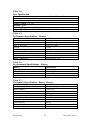
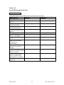
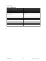
P/N 105-012
Nov. 2013 - Rev.4
AutoCPR Model 6000
AutoCPR User Information
The following user instructions for the AutoCPR Model 6000 must be read prior to using
AutoCPR. The device is for use by CPR certified care providers as an adjunct to manual
CPR. Always follow user instructions and contact an AutoCPR representative if user
instructions are not understood. This device may be purchased only on the order of a
licensed physician or medical practitioner.
The manufacturer will make available on request circuit diagrams, component part lists,
descriptions, calibration instructions, or other information that will assist service
personnel to repair those parts of the AutoCPR Model 6000 that are designated by the
manufacturer as repairable by service personnel.
AutoCPR® is a registered international trademark.
Declaration of Conformity
AutoCPR complies with the requirements of the European Medical Device Directive
93/42/EEC.
0120
Copyright AutoCPR 2010
AutoCPR
8800 Grow Dr.
Pensacola, Florida 32514
USA
Authorized Representative
Sébastien Vandamme
76 rue Colette
76620 Le Havre, France
Tel. +1 850 477-2324
Tel. +33 6 43 90 70 65
P/N 105-012
Nov. 2013 - Rev.4
Table Of Content
Safety Precautions......................................................................................... 1
Warning ................................................................................................ 1
Caution.................................................................................................. 2
Symbols .......................................................................................................... 3
1.0
2.0
3.0
4.0
5.0
6.0
7.0
Introduction ........................................................................................ 5
1.1 Indications for use ...................................................................... 5
1.2 Contraindications ....................................................................... 5
1.3 Description ................................................................................. 5
AutoCPR Components ....................................................................... 5
2.1 Controller ................................................................................... 6
2.2 Oxygen Ventilator ...................................................................... 6
2.3 Timer Assembly ......................................................................... 6
2.4 Air Supply .................................................................................. 6
2.5 Oxygen Supply ........................................................................... 6
2.6 Patient Kit................................................................................... 6
2.7 Patient Platform .......................................................................... 7
2.8 Battery Charger .......................................................................... 8
User Controls and Indicators ............................................................ 9
3.1 Oxygen and Air Connections ..................................................... 9
3.2 On/Off Power Button ................................................................. 9
3.3 Patient Airway Pressure Gauge.................................................. 9
3.4 Oxygen Ventilator .................................................................... 10
3.5 Ventilator Volume Selector...................................................... 10
3.6 Oxygen Ventilator Outlet ......................................................... 10
3.7 Control Selectors ...................................................................... 10
Using AutoCPR ................................................................................. 11
4.1 Preparing AutoCPR for Use ..................................................... 11
4.2 AutoCPR Operating Procedure ................................................ 12
4.3 AutoCPR in Operation ............................................................. 16
Return of Spontaneous Circulation ................................................ 16
Completion of Resuscitation Procedures ....................................... 17
6.1 Cleaning After Use ................................................................... 17
6.2 Preparing for Next Use............................................................. 17
AutoCPR Maintenance .................................................................... 18
7.1 Battery Replacement ................................................................ 19
P/N 105-012
Nov. 2013 - Rev.4
8.0
Tables: Performance Specifications – AutoCPR .......................... 20
Table 1-1 Compression Cuff Sizing ................................................... 20
Operating Parameters ........................................................ 20
Table 1-2 Physical Specifications ...................................................... 20
Table 1-3 Environmental Specifications ............................................ 20
Table 1-4 Fuse Specification .............................................................. 21
Table 1-5 Performance Specifications – Battery................................ 21
Table 1-6 Environmental Specifications – Battery ............................ 21
Table 1-7 Performance Specifications –Battery Charger................... 21
Table 1-8 Environmental Specifications –Battery Charger ............... 22
Table 1-9 Technical Specifications – Medical Oxygen Supply ......... 22
Table 1-10 Technical Specifications – Air Supply ............................ 22
Table 1-11 AutoCPR System Check List ........................................... 23
Table 1-12 AutoCPR Parts List .......................................................... 24
P/N 105-012
Nov. 2013 - Rev.4
Safety Precautions
Safety precautions are indicated throughout the user instructions manual by the bold
legends, Warning or Caution. The Warning legend alerts the user to avoid a possible
hazardous situation which may result in serious injury or death. The Caution legend
alerts the user of a possible hazardous situation which could result in injury and is to be
avoided.
Warning
• AutoCPR is to be used only by persons trained in manual CPR
• Do not use AutoCPR on patients less than 18 years of age
• Do not use AutoCPR on patients with chest or abdomen wounds
• Do not use AutoCPR if the patient is pregnant
• Do not use AutoCPR if the patient is too small or too large
• Always attend to patient during operation of AutoCPR
• During automatic ventilations, if patient airway pressure rises above 55cmH2O or
•
•
•
•
•
•
•
•
if patient valve alarm sounds, check patient airway for obstruction
Clear patient airway before resuming automatic ventilations
Prevent contaminants from entering air and oxygen connections
If system components do not function according to user manual instructions, turn
off controller air and oxygen supplies, press OFF power button, open chest cuff
and resume manual CPR
If empty air supply cylinders cannot be replaced immediately, open chest cuff and
resume manual CPR. Press power button OFF and disconnect components
Do not charge battery in wet areas
Do not charge the battery while operating the AutoCPR
Do not perform AutoCPR maintenance while operating the AutoCPR
Warning: No modification of this equipment is allowed
P/N 105-012
1
Nov. 2013 - Rev.4
Caution
• The patient platform is not intended to be used for transporting or carrying
•
•
•
•
•
•
•
•
•
•
•
•
•
•
•
patients
When transporting the patient the platform should be attached securely onto a
backboard, gurney or other medical transportation means
Securing straps must not interfere with patient compression cuffs or hoses
Use only accessories included in the user instructions manual
Do not allow liquids, dirt or sand to enter the AutoCPR controller
The battery is to be recharged after use or within twelve hours after the low
battery warning light begins flashing to prevent permanent battery damage
Follow all operating instructions in the user manual
Apply compression cuffs tightly around patient chest, abdomen and legs
Do not cut or puncture patient compression cuffs
During operation of the AutoCPR controller, if the low battery light begins
flashing, the controller will operate for an additional 45 minutes
The AutoCPR Patient Kit is for single use only. Used components are to be
treated as contaminated medical waste and disposed of as required by local
authority
Do not re-use AutoCPR Patient Kit. Re-use of single use Patient Kit may result
in inadequate cleaning and decontamination, residues from decontamination
agents, cross-contamination, material alteration, and/or device failure
Do not use AutoCPR Patient Kit if packaging seal has been opened or if
packaging has been damaged
Use only AutoCPR approved accessories. Use of non-AutoCPR accessories will
result in ineffective operation.
Use only AutoCPR battery charger supplied with the unit. Other type battery
chargers may incorrectly charge and damage battery possibly resulting in injury
to operating personnel.
If an air compressor is used to inflate compression cuffs, the compressor air
supply temperature is to be monitored and is not to exceed 41°C.
P/N 105-012
2
Nov. 2013 - Rev.4
AutoCPR Symbols
Symbols located throughout the user manual, on the controller and patient kit conform to
EN Standards. Their use reduces the need for translations of words into national
languages.
Automatic Operating Position
Airway Pressure Measurement
Single Use Only – Do Not Reuse
Ventilator
Operating Instructions
Date of Manufacture
ON/OFF
ON
OFF
Type BF Patient Connection
P/N 105-012
3
Nov. 2013 - Rev.4
Serial Number
O2
Oxygen Supply
AIR
Air Supply
Manufacturer
Authorized Representative
DC Input
P/N 105-012
4
Nov. 2013 - Rev.4
1.0
Introduction
Current methods of cardiopulmonary resuscitation require manual or mechanical devices
to provide chest compressions and airway management and often a ratio of three care
providers to one patient is required. In a hospital environment this is a significant
physical demand, but in the pre-hospital setting this effort often yields unfortunate
results. Under optimal conditions, circulation and ventilation requirements are fatiguing
labors for care providers. The AutoCPR device assumes both of these functions and once
started provides automatic, uninterrupted cardiopulmonary resuscitation. AutoCPR
combines external chest compressions synchronized with external counterpulsation to
provide forward blood flow hemodynamically. Integrated into the device is a time cycled
and pressure limited oxygen ventilator for pulmonary resuscitation.
1.1
Indications for use
AutoCPR is for use on adult patients only as an adjunct to manual cardiopulmonary
resuscitation in cases of clinical death as defined by lack of spontaneous breathing and
pulse.
1.2
•
•
•
•
•
1.3
Contraindications
Patients under 18 years of age
Patients with chest or abdominal wounds
Pregnancy
Patient too small
Patient too large
Description
AutoCPR is a portable system for use by emergency medical teams or other first
responders as an adjunct to manual CPR. It combines into a single resuscitation system:
• External chest compressor
• External counterpulsation to provide forward blood flow hemodynamically
• Oxygen ventilator
2.0
•
•
•
•
•
AutoCPR Components
Controller
Air supply hose with unique connector
Oxygen supply hose with unique connector
Patient Kit (patient-contacting)
Battery Charger
P/N 105-012
5
Nov. 2013 - Rev.4
2.1
Controller
The AutoCPR controller utilizes a source of compressed oxygen for patient ventilation
and compressed air to cyclically inflate legs, abdomen and chest compression cuffs to
provide cardiopulmonary resuscitation by inducing circulation in patients clinically dead
as defined by lack of spontaneous breathing and pulse. The portable controller assembly
provides inflation cuff sequence, pressure and cycle rate. An oxygen ventilator integrated
into the controller provides uninterrupted pulmonary resuscitation in proper timing with
cuff inflations.
2.2
Oxygen Ventilator
The oxygen ventilator includes a ventilator volume selector and demand breathing
regulator. The ventilator outlet connects to the oxygen delivery tube, patient valve and
mask.
2.3
Timer Assembly
The automatic function of AutoCPR is controlled by an electronic timer assembly
powered by a small battery.
2.4
Air Supply
The AutoCPR controller receives pressure reduced air from a wall outlet, air compressor
or portable compressed air cylinder. The air supply hose has a unique female connector
that fits only the male air connector on the controller. The opposite end of the supply
hose is connected to the pressure reduced air supply. (Reference Table 1-10 for
specifications of regulated air supply sources)
2.5
Oxygen Supply
The AutoCPR controller receives pressure reduced medical oxygen from an oxygen
cylinder or wall outlet. The oxygen supply hose has a unique female connector that fits
only the male oxygen connector on the controller. The opposite end of the supply hose is
connected to the pressure reduced oxygen supply. (Reference Table 1-9 for specifications
of regulated oxygen supply sources)
2.6
Patient Kit
The patient kit includes the following type B applied parts:
• Patient platform
• Compression cuffs: chest, abdomen and leg cuffs
• Cuff hoses with non-interchangeable and color coded connectors
• Oxygen delivery tube, patient valve assembly and mask
The patient kit is defibrillation-proof and can be used in conjunction with an AED.
P/N 105-012
6
Nov. 2013 - Rev.4
2.7
Patient Platform
AutoCPR,
latex
free
compression
cuffs
are
attached to the patient
platform in a ready position
for immediate application.
The platform aids medical
professionals when applying
the compression cuffs to the
patient.
The cuffs have
inflatable bladders that are
held in place on the patient by
straps with hook and loop
fasteners. Leg cuffs are applied to the thigh of each leg and secured with hook and loop
fastened straps. Color coded and non-interchangeable hose connectors mate with
corresponding connectors on cuffs and system controller. During AutoCPR operation,
cuffs cycle sequentially; first the legs followed by the abdomen and then the chest. Chest
and abdomen cuffs cycle in counter phase at a combined rate of sixty compressions a
minute. Leg cuffs cycle at a rate of five compressions a minute.
Table 1-1
Compression Cuff Sizing
Chest circumference
Abdomen circumference
Leg/thigh circumference
Maximum patient weight
64cm to 145cm
66cm to 145cm
36cm to 66cm
136 kg
Warning:
The platform is not intended to be used for transporting or carrying patients. When
transporting the patient, the platform should be attached securely onto a backboard,
gurney or other medical transportation means. Securing straps must not interfere with
patient cuffs and hoses.
P/N 105-012
7
Nov. 2013 - Rev.4
2.8
Battery Charger
The controller battery is the internal power supply for AutoCPR and is connected to the
electronic system. The battery is recharged in place with the external charger. The
battery charger is connected to the DC input on the back side of the controller case. The
battery charger cord must be plugged into a 220 VAC/50Hz wall socket. (Reference
Tables 1-5 and 1-6 for battery specifications) The battery charger is not intended to be
used during AutoCPR operation. The battery should be fully charged before using and
will run the AutoCPR unit for sixty minutes before the low battery indicator turns on.
Use only AutoCPR battery charger supplied with unit.
Caution – Low Battery
A red LED low battery warning light is located on the front side of the case. When the
red warning light starts flashing, the battery will operate the unit for 45 minutes. Start
battery recharge within twelve hours of the initial low battery warning to avoid
permanent damage to the battery.
P/N 105-012
8
Nov. 2013 - Rev.4
3.0
User Controls and Indicators
User controls and indicators are positioned on the AutoCPR controller panel.
On/Off Button
Airway Pressure
Ventilator Volume
Selector
Ventilator Outlet
Oxygen Supply
Air Supply
Chest Cuff
Connection
Off/Chest Cuff
Automatic/Chest Cuff
Abdomen Cuff
Connection
Leg Cuffs
Connection
Off/Abdomen Cuff
Automatic/Abdomen Cuff
Off/Leg Cuffs
3.1
On/Leg Cuffs
Automatic/Leg Cuffs
Oxygen and Air Connections
O2 ¯ AIR
Oxygen and air supply connections on the AutoCPR controller have
unique connection means that are non-interchangeable.
3.2
On/Off Power Button
The ON/OFF power button is located at the top left corner of the controller. A
green LED in the middle of the button lights when in the ON mode. When the button is
pressed a second time the AutoCPR controller ceases operation and the light turns Off.
3.3
Patient Airway Pressure Gauge
A gauge measures patient airway pressure during automatic oxygen ventilation.
The gauge has graduates of 0 to 75 cmH2O.
Warning:
• During automatic oxygen ventilation if airway pressure rises above 55 cmH2O or
if patient valve alarm sounds, check patient airway for obstruction.
• Clear patient airway before resuming automatic ventilation
P/N 105-012
9
Nov. 2013 - Rev.4
3.4
Oxygen Ventilator
The oxygen ventilator has two modes of operation: Automatic and Demand
• The Automatic setting is controlled by the ventilator volume selector and is used
during resuscitation.
• The Demand setting is also controlled by the ventilator volume selector and is
used when the resuscitated patient is spontaneously breathing.
3.5
Ventilator Volume Selector
The ventilator volume selector has four positions for levels of patient tidal
volume and one Demand position for patient spontaneous breathing. Each position is
calibrated for a flow that when matched with the electronic timer allows for a fixed
volume of oxygen to flow to the patient. The patient ventilator is time cycled and
pressure limited. The ventilator automatically cycles in phase with every second
abdomen cuff compression to reduce the possibility of gastric insufflation and pulmonary
aspiration of gastric contents.
Patient oxygen ventilation is selectable at 400, 600, 800 or 1000 milliliters for each cycle.
The proper ventilator volume setting is determined by multiplying the patient weight by
8-10 ml. /kg. If the resuscitated patient requires additional oxygen flow, the demand
feature of the ventilator provides additional flow to meet patient demand.
3.6
Oxygen Ventilator Outlet
The oxygen ventilator has a standard 22mm outlet connection for the oxygen delivery
tube, patient valve assembly and mask. The 22mm outlet is a unique male connector for
the oxygen delivery tube. The patient valve assembly includes an alarm whistle that
sounds a tone when pressure in the outlet exceeds 55 cmH2O
3.7
Control Selectors
Compression cuff control selectors are located in the center of the AutoCPR control panel
and their operating positions are marked with the following symbols:
Automatic position
Off position
On position
P/N 105-012
10
Nov. 2013 - Rev.4
•
•
•
The Chest Cuff Control Selector has two positions:
o
Automatic
o
Off
The Abdomen Cuff Control Selector has two positions:
o
Automatic
o
Off
The Leg Cuffs Control Selector has three positions:
o
Automatic
o
Off
o
On
§ The leg cuff ON position is for use when the patient has wounds to
the leg(s).
4.0
Using AutoCPR
Warning
• For use only on patients 18 years of age or older
• For use by CPR certified care providers as an adjunct to manual CPR
• Not to be used on patients that are pregnant
• Not to be used on patients with chest or abdominal wounds
• Not to be used on patients too small or too large
4.1
Preparing AutoCPR for Use
Before using AutoCPR the controller should be set to the following positions:
• Oxygen Ventilator Volume Selector set to the 600 milliliter position
• Chest Cuff Selector set to the Automatic position
• Abdomen Cuff Selector set to the Automatic position
• Leg Cuffs Selector set to the Off position
P/N 105-012
11
Nov. 2013 - Rev.4
4.2
AutoCPR Operating Procedure
The following procedure for operating the AutoCPR resuscitation system requires two
persons trained and certified in cardiopulmonary resuscitation
• Remove patient kit from its protective bag.
• After determining the condition of the patient, set the patient in the upright
position
• Place the platform with the attached chest and abdomen cuffs behind the patient
with person symbol pointing in the direction of the patient’s head
P/N 105-012
12
Nov. 2013 - Rev.4
•
Rapidly pull cuff lanyard completely away from platform to expose abdomen
and chest cuffs in ready position
•
Lay patient’s back onto the platform
•
Alternately, place the platform and cuffs to the patient’s side and roll the
patient’s back onto the platform.
P/N 105-012
13
Nov. 2013 - Rev.4
•
First attendant:
o Apply chest cuff tightly around patient directly below the armpits with
center of cuff above sternum. Secure fasteners.
o Apply abdomen cuff tightly around patient and with center of cuff above
abdomen. Secure fasteners.
o Do not place cuff around patient stomach
o Connect blue hose connector to chest cuff
o Connect yellow hose connector to abdomen cuff
Defibrillator pads will not effect operation of AutoCPR chest cuff
•
Second attendant:
o Connect air supply hose to AutoCPR controller
§ Turn On air supply valve
o Connect oxygen supply hose to AutoCPR controller
§ Turn On oxygen supply valve
P/N 105-012
14
Nov. 2013 - Rev.4
o Connect (blue) chest cuff hose to controller
o Connect (yellow) abdomen cuff hose to controller
o Connect oxygen delivery hose with patient valve and mask to ventilator
outlet on controller
o Press ON/OFF power button on controller – green indicator lights
o Apply oxygen mask to patient airway
P/N 105-012
15
Nov. 2013 - Rev.4
•
4.3
First attendant:
o Apply leg cuffs tightly around each leg close to the groin
o Connect (red) legs cuff hose to controller
o Turn Leg cuff selector to Automatic
AutoCPR in Operation
With Cuff Selectors set to the Automatic positions and ventilator volume selected, the
controller provides inflation cuff sequence, pressure, and cycle rate and oxygen
ventilation.
5.0
•
•
Return of Spontaneous Circulation
Upon return of spontaneous circulation:
o Turn Chest Cuff Selector to OFF position
o Disconnect chest cuff hose from controller
o Continue to cycle abdomen and leg cuffs to provide circulation support
o Continue to cycle oxygen ventilator
o If patient begins spontaneous breathing, turn ventilator volume selector to
the Demand setting
If patient returns to cardiac arrest:
o Connect chest cuff hose to controller
o Turn Chest Cuff Selector to ON position
o Turn Ventilator Volume Selector to the appropriate volume setting
P/N 105-012
16
Nov. 2013 - Rev.4
6.0
•
Completion of Resuscitation Procedures
Upon completion of resuscitation procedures:
o Press ON/OFF power button – green indicator light turns off and
automatic cuff cycles and oxygen ventilation cycles cease.
o Remove oxygen mask from patient airway
o Turn OFF chest, abdomen and leg cuff selectors
o Disconnect chest, abdomen and leg cuff hoses from controller
o Open chest, abdomen and leg cuff fasteners
o Turn off air supply and disconnect from controller
o Turn off oxygen supply and disconnect from controller
Caution
• Patient platform, tubing, compression cuffs, oxygen delivery tube, valve and
mask are for single use only.
• Single use components are to be treated as contaminated medical waste and
disposed of as required by local authority
6.1
•
•
6.2
•
•
•
•
•
•
•
Cleaning After Use
Clean all exposed surfaces of the AutoCPR controller with a cloth and isopropyl
alcohol or other disinfectant.
Allow cleaned surface to completely dry before closing the case
Preparing for Next Use
Pre-set the controls to the following positions:
o Oxygen Ventilation Volume Selector set to the 600 ml. position
o Chest Cuff Selector set to the Automatic position
o Abdomen Cuff Selector set to the Automatic position
o Leg Cuff Selector set to the OFF position
Select new patient kit
The controller battery is recharged by connecting the battery charger to its
connection on the back side of the case and plugging the cord into a
220VAC/50Hz electrical outlet.
The battery charger will maintain the battery in a ready position if connected
when the controller is not in use. Use only AutoCPR battery charger supplied
with unit.
The battery, if not connected to the battery charger, will maintain a full charge for
60 hours (with unit off) before low battery indicator lights.
A flashing red low battery indicator light on the front of the case indicates the
battery requires recharging.
Battery charging must be started within 12 hours after the flashing indicator lights
to prevent permanent damage to the battery.
P/N 105-012
17
Nov. 2013 - Rev.4
Caution
If the low battery indicator light remains flashing after four hours of charging, do not
use the AutoCPR and contact the manufacturer or local service technician for
maintenance.
7.0
•
AutoCPR Maintenance
After use cleaning and replacement of the battery are the only user maintenance
items in AutoCPR
• Maintain controller assembly connected to battery charger when not in use
• If the low battery warning light does not turn off after four hours of battery
charging or if device does not operate according to user manual instructions,
contact the local AutoCPR technician or manufacturer.
In addition to after use cleaning, the device should be inspected weekly or more
frequently if used several times monthly. Reference: Table 1-11 for AutoCPR system
check list.
The internal battery must be replaced after 100 use cycles or annually, whichever occurs
first. See manual instructions for battery replacement. Servicing of the AutoCPR
controller is recommended every five years. If the controller does not operate according
to manual instructions do not use and contact the manufacturer or local servicing
technician for maintenance.
User preventive maintenance
• Inspect all inlet and outlet connections on AutoCPR controller for contaminants
• Check the operation of control valves, oxygen selector and ON/OFF power
button
• Check that the battery charger is connected to the controller and plugged into a
wall socket when the device is not in use
• Inspect the controller and case for apparent physical damage
• Check that an unopened patient kit is accessible
• Check patient kit label for expiration date. Do not use if kit has expired date.
Factory maintenance
• Return AutoCPR controller to service center or manufacturer if it does not
operate according to User Manual.
• AutoCPR controller should be returned to service center or manufacturer for
maintenance after five years of service time
Warning
Unless specified otherwise, repairs and servicing must be carried out by AutoCPR
approved service technicians. Failure to follow these conditions may lead to
patient/operator injury or death.
P/N 105-012
18
Nov. 2013 - Rev.4
7.1
Battery Replacement
•
•
•
•
•
•
•
•
•
•
•
P/N 105-012
Open controller case and remove four panel screws
Lift panel and disconnect cable from panel assembly
Remove controller panel from case
Disconnect battery cable
Remove four screws from battery box cover
Remove battery box cover and battery
Insert new battery and connect cable
Replace battery box cover and fasten with four screws
Connect cable to panel assembly
Set in place controller panel and fasten with four screws
Press power button and check for green indicator light
19
Nov. 2013 - Rev.4
8.0 Performance Specifications – AutoCPR
Table 1-1
Patient Size
Chest circumference
Abdomen circumference
Leg/Thigh circumference
Maximum patent weight
Operating Parameters
Sternal depression
Sternal depression force
Compression sequence
Total compression rate
Total duty cycle
Oxygen ventilation
Oxygen ventilation sequence
Specifications
64cm to 145cm
66cm to 145cm
36cm to 66cm
136 kg
Specifications
4cm to 5cm
45 kg
Legs – abdomen – chest
65 continuous
65 continuous
Automatic – 15 ventilations/minute
Phased w/ each 2nd abdomen compression
Table 1-2
Physical Specifications
Controller
Patient kit
Dimensions
48 x 36 x 18 cm
91 x 41 x 15 cm
Weight
8.6 kg
3.5 kg
Table 1-3
Environmental
Operating temperature
Storage temperature
Relative humidity
Safety classification
Specifications
0ºC to +45ºC
0ºC to +45ºC
5% to 95%, non-condensing
Meets EN 60601, internally powered, Type
BF, movable, short time operation, 60
minutes
IP Classification
IP20
Electromagnetic Susceptibility
Meets EN 61000-4-3,4,5 and 6
RF Emissions
Device uses or produces no RF energy for
its internal function
Electrostatic Discharge
Meets EN 61000-4-2
Electromagnetic Radiated Immunity
Meets EN 61000-4-3
Electromagnetic Conducted Immunity
Meets EN 61000-4-6 10Vrms
Corrosion resistance
External components non-corrosive
Operating Classification
Short time EN 60601-1, 60 minutes
AutoCPR is suitable for use in all buildings including the home, commercial or hospital
environment and meets the requirements of EN 60601-1-2. Susceptibility can not be
assured outside of this environment
P/N 105-012
20
Nov. 2013 - Rev.4
Table 1-4
Fuse Specification
Description: Battery and charger fuses mounted to Controller circuit board
Fuse Type: Resettable PTC – not user serviceable
Mounting Type: Surface Mount
Voltage – Rated: 13.2 VDC
Current: 500mA
Operating Temperature: -40°C to +85°C
Approvals: UL File No. E183209, TUV File No. R50082521
Table 1-5
Performance Specifications – Battery
Battery
Battery type
Battery make and model
Size: (L x W x H)
Weight
Nominal voltage
Nominal capacity
Nominal operating time/charged
Battery charge time
Battery replacement
Specifications
Rechargeable sealed lead acid battery
Power Sonic PS-1208
96 x 25 x 62 mm
0.36 kg
12 volts
0.80 AH
+60 minutes
4 hours
100 cycles or 1 year
Table 1-6
Environmental Specifications – Battery
Battery
Operating temperature range
Charge temperature range
Storage temperature range
Operating altitude
Specifications
0ºC to +45ºC
+5ºC to +35ºC
0ºC to +45ºC
3,050 meters
Table 1-7
Performance Specifications –Battery Charger
Battery Charger
Battery charger type
Model Number
Size: (L x W x H)
Weight
Operating voltage
Operating frequency
Voltage output
Insulation class
Battery Charge
Fuses
P/N 105-012
Specifications
Lead acid charger, WPI, 1.3 A
452241-SB
121 x 76 x 57mm
0.70 kg
230 VAC
50 Hz
13.8 Vdc @ 290 mA
Class II
4 hours
Auto reset thermal breaker
21
Nov. 2013 - Rev.4
Table 1-8
Environmental Specifications –Battery Charger
Battery Charger
Operating temperature
Storage temperature
Relative humidity
Safety requirements
Electromagnetic emissions
Harmonic emissions
Voltage fluctuations/flicker emissions
Electrostatic discharge
Electromagnetic immunity
Electrical fast transient/burst
Surge
Power frequency (50/60 Hz) magnetic
field
Voltage dips, short interruptions and
voltage variations on power supply input
lines
Specifications
0ºC to +40ºC
0ºC to +45ºC
5% to 95% non-condensing
Meets UL60601-1 & CE LVD EN60601-1
Meets EN 55011 Group1, Class A
Meets EN 61000-3-2
Meets EN 61000-3-3
Meets EN 61000-4-2
Meets EN 61000-4-3 and -6
Meets EN 61000-4-4
Meets EN 61000-4-5
Meets EN 61000-4-8
Meets EN 61000-4-11
Table 1-9
Technical Specifications – Medical Oxygen Supply
Pressure Regulators or Wall Outlet
Minimum Pressure: 3.5 bar
Nominal Pressure: 4.0 bar
Maximum Pressure: 5.0 bar
Minimum Flow Rate: 50 liters/minute
Table 1-10
Technical Specifications – Medical Grade/Breathing Quality Air
Pressure Regulators or Wall Outlet
Minimum Pressure: 4.5 bar
Nominal Pressure: 5.0 bar
Maximum Pressure: 8.0 bar
Minimum Flow Rate: 75 liters/minute
P/N 105-012
22
Nov. 2013 - Rev.4
Table 1-11
AutoCPR System Check List
Date:
Operational status of AutoCPR should be checked weekly as follows:
Inspection List
Inspector
Comments
All exposed surfaces clean
Ventilator volume set to
600 ml
Chest cuff selector set to
automatic position
Abdomen cuff selector set
to automatic position
Leg cuff selector set to Off
position
Battery charger connected
Test function of power On
button – LED lights
Low battery indicator light
is Off
Inspect inlet and outlet
connectors for
contaminants
Inspect AutoCPR
controller for physical
damage
Connect air supply hose to
controller and functionally
test the controller
Connect oxygen supply
hose to controller and
functionally test ventilator
Check for accessible
patient kit
P/N 105-012
23
Nov. 2013 - Rev.4
Table 1-12
AutoCPR Parts List
Part Description
AutoCPR Controller
Patient Kit
Patient Kit (For Training Use Only)
Air Supply Hose with Connector
Oxygen Supply Hose with Connector
Battery Charger
Battery
P/N 105-012
Part Number
200-018
215-051
215-053
215-059
215-060
170-008
170-004
24
Nov. 2013 - Rev.4