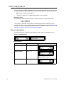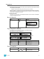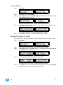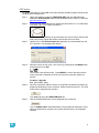
1
Control Console User Manual Version 3.0 C o p y r i g h t © 2 0 1 0 . E le c tr o n i c T h e a t r e C o n t r o l s , I n c . All Rights reserved. P r o d u c t in f o r m a t i on a n d s p e c i f i c a t i o n s s u bj e c t t o c h a n g e . P a r t N u m b e r : 7219M1210-3.0.0 R e v A R e le a s ed : 2 0 1 0 - 1 1 E T C pe r m i t s t h e r e p r o d u c t i o n o f m a t e r i a l s i n th i s m a n u a l o n l y f o r n o n - c o m m e r c i a l p u r p o s e s . A l l o t h e r r i g h ts ar e reserved by ETC. ET C ®, E m p h a s i s ®, E x p r e s s i o n ®, I n s i g h t ™ , I m ag i n e ™ , F o c u s ™ , E x p r e s s ™ , U n i s o n ®, O b s e s s i o n ® I I, S m a r t P a c k ®, S m a r t F a d e ™ , E T C N e t2 ™ , E D M X ™ , S o u r c e F o u r ®, R e v o l u t i o n ®, S e n s o r ®, a n d W Y S I L i n k ™ a r e e i t h e r r e g i s t e r e d t r a d e m a r k s o r t r a d e m a r k s o f E l e c t r o n i c T h e a t r e C o n t r o ls , I n c . i n t h e U n i t e d S t a t e s a n d o th e r c o u n t r i e s . M i c r o s o f t ® a n d W i n d o w s ® a r e r e g i s t e r e d t r a d e ma r k s o f M i c r o s o f t C o r p or a t i o n in t h e U n i t e d S t a t e s a n d o t h e r countries. A l l o t h e r t r a d em a r k s , b o t h m a r k e d a n d n o t m a r k e d , a r e th e p r o p e r t y o f t h e i r r e s p e c t i v e o w n e r s . Table of Contents Introduction . . . . . . . . . . . . . . . . . . . . . . . . . . 1 Using this Manual . . . . . . . . . . . . . . . . . . . . . . . . . . . . . . . . . . . . . . . .2 Instructions . . . . . . . . . . . . . . . . . . . . . . . . . . . . . . . . . . . . . . . . .2 Menu Directions. . . . . . . . . . . . . . . . . . . . . . . . . . . . . . . . . . . . . .2 Text Conventions. . . . . . . . . . . . . . . . . . . . . . . . . . . . . . . . . . . . .2 Help from ETC Technical Services . . . . . . . . . . . . . . . . . . . . . . . . . .3 Power-up and Shutdown Procedures. . . . . . . . . . . . . . . . . . . . . . . . .4 Unpack & Connect. . . . . . . . . . . . . . . . . . . . . . . . . . . . . . . . . . . .4 Power-up Procedure . . . . . . . . . . . . . . . . . . . . . . . . . . . . . . . . . .4 Shutdown Procedure . . . . . . . . . . . . . . . . . . . . . . . . . . . . . . . . . .4 Operating Modes . . . . . . . . . . . . . . . . . . . . . . . . . . . . . . . . . . . . .5 Save & Load to Memory Card . . . . . . . . . . . . . . . . . . . . . . . . . . . . . .6 Save Show to Card . . . . . . . . . . . . . . . . . . . . . . . . . . . . . . . . . . .6 Quick Save Show to Card . . . . . . . . . . . . . . . . . . . . . . . . . . . . . .6 Load show from Card . . . . . . . . . . . . . . . . . . . . . . . . . . . . . . . . .6 Load Patch from Card . . . . . . . . . . . . . . . . . . . . . . . . . . . . . . . . .7 Load User Personalities from Card . . . . . . . . . . . . . . . . . . . . . . .7 Load Personalities from Card . . . . . . . . . . . . . . . . . . . . . . . . . . .7 Format SD Memory Card. . . . . . . . . . . . . . . . . . . . . . . . . . . . . . .8 Chapter 1 General Information . . . . . . . . . . . . . . . . . . . 9 Control Capacity . . . . . . . . . . . . . . . . . . . . . . . . . . . . . . . . . . . . . . . .10 Frontpanel Functionality . . . . . . . . . . . . . . . . . . . . . . . . . . . . . . . . . .11 General Buttons. . . . . . . . . . . . . . . . . . . . . . . . . . . . . . . . . . . . .11 Faders & Bump Buttons. . . . . . . . . . . . . . . . . . . . . . . . . . . . . . .12 Master & Black Out Function . . . . . . . . . . . . . . . . . . . . . . . . . . .12 Independents . . . . . . . . . . . . . . . . . . . . . . . . . . . . . . . . . . . . . . .12 Crossfader . . . . . . . . . . . . . . . . . . . . . . . . . . . . . . . . . . . . . . . . .13 Sequence & Stack Functions. . . . . . . . . . . . . . . . . . . . . . . . . . .13 Record & Edit Functions . . . . . . . . . . . . . . . . . . . . . . . . . . . . . .13 The Select Section. . . . . . . . . . . . . . . . . . . . . . . . . . . . . . . . . . .13 LCD & Wheel Functions . . . . . . . . . . . . . . . . . . . . . . . . . . . . . .14 Philosophy of the Console . . . . . . . . . . . . . . . . . . . . . . . . . . . . . . . .15 HTP and LTP control rules . . . . . . . . . . . . . . . . . . . . . . . . . . . .15 Different Ways to Use SmartFade ML . . . . . . . . . . . . . . . . . . . .15 Data Structure & Timing . . . . . . . . . . . . . . . . . . . . . . . . . . . . . . . . . .16 Chapter 2 Setup . . . . . . . . . . . . . . . . . . . . . . . . . . . . . 17 DMX Output . . . . . . . . . . . . . . . . . . . . . . . . . . . . . . . . . . . . . . . . . . .18 DMX Out Speed. . . . . . . . . . . . . . . . . . . . . . . . . . . . . . . . . . . . .18 Clear/Set Patch . . . . . . . . . . . . . . . . . . . . . . . . . . . . . . . . . . . . . . . .19 Clear Intensity Patch . . . . . . . . . . . . . . . . . . . . . . . . . . . . . . . . .19 Set Intensity Patch 1:1. . . . . . . . . . . . . . . . . . . . . . . . . . . . . . . .19 i Clear Device Patch . . . . . . . . . . . . . . . . . . . . . . . . . . . . . . . . . .19 Patch Dimmers (INT) . . . . . . . . . . . . . . . . . . . . . . . . . . . . . . . . . . . .20 Patch by Dimmer . . . . . . . . . . . . . . . . . . . . . . . . . . . . . . . . . . . .20 Patch by Channel . . . . . . . . . . . . . . . . . . . . . . . . . . . . . . . . . . .21 Patch Independents . . . . . . . . . . . . . . . . . . . . . . . . . . . . . . . . . . . . .22 Set up Independents . . . . . . . . . . . . . . . . . . . . . . . . . . . . . . . . .22 Patch Devices . . . . . . . . . . . . . . . . . . . . . . . . . . . . . . . . . . . . . . . . .23 Device Personalities . . . . . . . . . . . . . . . . . . . . . . . . . . . . . . . . .23 Patch Multiple Devices . . . . . . . . . . . . . . . . . . . . . . . . . . . . . . .23 Device Commands . . . . . . . . . . . . . . . . . . . . . . . . . . . . . . . . . .24 View/Modify Device Patch . . . . . . . . . . . . . . . . . . . . . . . . . . . . .24 Device Settings . . . . . . . . . . . . . . . . . . . . . . . . . . . . . . . . . . . . .25 Console Setup . . . . . . . . . . . . . . . . . . . . . . . . . . . . . . . . . . . . . . . . .26 Erase Functions. . . . . . . . . . . . . . . . . . . . . . . . . . . . . . . . . . . . .26 Default Times. . . . . . . . . . . . . . . . . . . . . . . . . . . . . . . . . . . . . . .26 Crossfade Faders . . . . . . . . . . . . . . . . . . . . . . . . . . . . . . . . . . .26 Memory Rubberband . . . . . . . . . . . . . . . . . . . . . . . . . . . . . . . . .27 DMX Out . . . . . . . . . . . . . . . . . . . . . . . . . . . . . . . . . . . . . . . . . .27 MIDI Settings . . . . . . . . . . . . . . . . . . . . . . . . . . . . . . . . . . . . . . .27 Language. . . . . . . . . . . . . . . . . . . . . . . . . . . . . . . . . . . . . . . . . .27 Displays . . . . . . . . . . . . . . . . . . . . . . . . . . . . . . . . . . . . . . . . . . .27 Software Version . . . . . . . . . . . . . . . . . . . . . . . . . . . . . . . . . . . .28 LED Calibration . . . . . . . . . . . . . . . . . . . . . . . . . . . . . . . . . . . . .28 Save LED Calibration . . . . . . . . . . . . . . . . . . . . . . . . . . . . . . . .28 Load LED Calibration. . . . . . . . . . . . . . . . . . . . . . . . . . . . . . . . .28 MIDI Setup . . . . . . . . . . . . . . . . . . . . . . . . . . . . . . . . . . . . . . . . . . . .29 MIDI Show Control. . . . . . . . . . . . . . . . . . . . . . . . . . . . . . . . . . .29 Synchronising Two SmartFades . . . . . . . . . . . . . . . . . . . . . . . .30 Basic MIDI Implementation . . . . . . . . . . . . . . . . . . . . . . . . . . . .30 MIDI Channel . . . . . . . . . . . . . . . . . . . . . . . . . . . . . . . . . . . . . .31 Sending MIDI Controllers. . . . . . . . . . . . . . . . . . . . . . . . . . . . . .31 Custom Moving Light Personalities . . . . . . . . . . . . . . . . . . . . . . . . .32 Custom Moving Light Personalities . . . . . . . . . . . . . . . . . . . . . .32 Open the Personality Editor. . . . . . . . . . . . . . . . . . . . . . . . . . . .32 Edit a Personality Live . . . . . . . . . . . . . . . . . . . . . . . . . . . . . . . .33 Special - Color Mix CMY, RGB & RAGB . . . . . . . . . . . . . . . . . .34 Edit a Personality Blind . . . . . . . . . . . . . . . . . . . . . . . . . . . . . . .34 Example (Blind) - Pan/Tilt 16 Bit . . . . . . . . . . . . . . . . . . . . . . . .36 Special - Fade With Intensity . . . . . . . . . . . . . . . . . . . . . . . . . . .37 Special - Invert Parameter . . . . . . . . . . . . . . . . . . . . . . . . . . . . .37 Chapter 3 Program . . . . . . . . . . . . . . . . . . . . . . . . . . . 39 Intensity Channels . . . . . . . . . . . . . . . . . . . . . . . . . . . . . . . . . . . . . .40 Live or Next Mode . . . . . . . . . . . . . . . . . . . . . . . . . . . . . . . . . . .40 Adjust Channel Range. . . . . . . . . . . . . . . . . . . . . . . . . . . . . . . .41 Set Channel Range . . . . . . . . . . . . . . . . . . . . . . . . . . . . . . . . . .41 Devices. . . . . . . . . . . . . . . . . . . . . . . . . . . . . . . . . . . . . . . . . . . . . . .42 Select Devices . . . . . . . . . . . . . . . . . . . . . . . . . . . . . . . . . . . . . .43 Device Groups . . . . . . . . . . . . . . . . . . . . . . . . . . . . . . . . . . . . . .44 ii SmartFade ML v3.0 User Manual Device Parameters . . . . . . . . . . . . . . . . . . . . . . . . . . . . . . . . . .45 Device Palettes . . . . . . . . . . . . . . . . . . . . . . . . . . . . . . . . . . . . .47 General Device Functions . . . . . . . . . . . . . . . . . . . . . . . . . . . . .48 Effects . . . . . . . . . . . . . . . . . . . . . . . . . . . . . . . . . . . . . . . . . . . . . . .51 Shape effects. . . . . . . . . . . . . . . . . . . . . . . . . . . . . . . . . . . . . . .51 Offset Relations In Shape and Color Effects . . . . . . . . . . . . . . .52 Color Effects . . . . . . . . . . . . . . . . . . . . . . . . . . . . . . . . . . . . . . .53 Linear Effects. . . . . . . . . . . . . . . . . . . . . . . . . . . . . . . . . . . . . . .54 Memories . . . . . . . . . . . . . . . . . . . . . . . . . . . . . . . . . . . . . . . . . . . . .55 Record a Memory . . . . . . . . . . . . . . . . . . . . . . . . . . . . . . . . . . .55 Snapshots . . . . . . . . . . . . . . . . . . . . . . . . . . . . . . . . . . . . . . . . . . . .57 Record a Snapshot . . . . . . . . . . . . . . . . . . . . . . . . . . . . . . . . . .57 Copy a Snapshot to a Memory . . . . . . . . . . . . . . . . . . . . . . . . .57 Clear all Snapshots . . . . . . . . . . . . . . . . . . . . . . . . . . . . . . . . . .57 Sequences . . . . . . . . . . . . . . . . . . . . . . . . . . . . . . . . . . . . . . . . . . . .58 Record a Sequence . . . . . . . . . . . . . . . . . . . . . . . . . . . . . . . . . .59 Stack . . . . . . . . . . . . . . . . . . . . . . . . . . . . . . . . . . . . . . . . . . . . . . . .60 Record the Stack from Bumps. . . . . . . . . . . . . . . . . . . . . . . . . .61 Record a Stack State or “Cue”. . . . . . . . . . . . . . . . . . . . . . . . . .62 Chapter 4 Edit . . . . . . . . . . . . . . . . . . . . . . . . . . . . . . . 65 Edit Memories . . . . . . . . . . . . . . . . . . . . . . . . . . . . . . . . . . . . . . . . .66 Edit a Memory . . . . . . . . . . . . . . . . . . . . . . . . . . . . . . . . . . . . . .66 Delete a Memory . . . . . . . . . . . . . . . . . . . . . . . . . . . . . . . . . . . .67 Delete Multiple Memories . . . . . . . . . . . . . . . . . . . . . . . . . . . . .67 Copy a Memory . . . . . . . . . . . . . . . . . . . . . . . . . . . . . . . . . . . . .67 Default Device Times. . . . . . . . . . . . . . . . . . . . . . . . . . . . . . . . .68 Memory FCB Times. . . . . . . . . . . . . . . . . . . . . . . . . . . . . . . . . .68 Edit Sequences & Stack . . . . . . . . . . . . . . . . . . . . . . . . . . . . . . . . . .69 Edit the Content of a Step . . . . . . . . . . . . . . . . . . . . . . . . . . . . .69 Delete a Step . . . . . . . . . . . . . . . . . . . . . . . . . . . . . . . . . . . . . . .70 Insert a Step . . . . . . . . . . . . . . . . . . . . . . . . . . . . . . . . . . . . . . .70 Insert a PointQ. . . . . . . . . . . . . . . . . . . . . . . . . . . . . . . . . . . . . .71 Change the Content of a Step . . . . . . . . . . . . . . . . . . . . . . . . . .71 Copy a Sequence . . . . . . . . . . . . . . . . . . . . . . . . . . . . . . . . . . .72 Delete a Sequence or the Stack . . . . . . . . . . . . . . . . . . . . . . . .72 Run Modes . . . . . . . . . . . . . . . . . . . . . . . . . . . . . . . . . . . . . . . .73 Sequence & Stack Times . . . . . . . . . . . . . . . . . . . . . . . . . . . . .74 Edit Effects . . . . . . . . . . . . . . . . . . . . . . . . . . . . . . . . . . . . . . . . . . . .77 Edit Shape Effects . . . . . . . . . . . . . . . . . . . . . . . . . . . . . . . . . . .77 Edit Linear Effects . . . . . . . . . . . . . . . . . . . . . . . . . . . . . . . . . . .78 Edit Color Effects . . . . . . . . . . . . . . . . . . . . . . . . . . . . . . . . . . . .79 Edit Palettes . . . . . . . . . . . . . . . . . . . . . . . . . . . . . . . . . . . . . . . . . . .80 Chapter 5 Playback . . . . . . . . . . . . . . . . . . . . . . . . . . . 81 General Functions . . . . . . . . . . . . . . . . . . . . . . . . . . . . . . . . . . . . . .82 Master & Black Out function . . . . . . . . . . . . . . . . . . . . . . . . . . .82 iii Clear . . . . . . . . . . . . . . . . . . . . . . . . . . . . . . . . . . . . . . . . . . . . .82 Bump Master . . . . . . . . . . . . . . . . . . . . . . . . . . . . . . . . . . . . . . .82 Memories . . . . . . . . . . . . . . . . . . . . . . . . . . . . . . . . . . . . . . . . . . . . .83 Select Fader Page . . . . . . . . . . . . . . . . . . . . . . . . . . . . . . . . . . .83 Memory Fader Modes . . . . . . . . . . . . . . . . . . . . . . . . . . . . . . . .83 Memory Bump Modes . . . . . . . . . . . . . . . . . . . . . . . . . . . . . . . .83 Clear Output from Memory Faders . . . . . . . . . . . . . . . . . . . . . .84 Examples of Using Memory Faders. . . . . . . . . . . . . . . . . . . . . .84 Sequences . . . . . . . . . . . . . . . . . . . . . . . . . . . . . . . . . . . . . . . . . . . .85 Select Fader Page . . . . . . . . . . . . . . . . . . . . . . . . . . . . . . . . . . .85 Sequence Bump Modes . . . . . . . . . . . . . . . . . . . . . . . . . . . . . .85 Rate & BPM for Sequences. . . . . . . . . . . . . . . . . . . . . . . . . . . .86 Stack & Crossfader . . . . . . . . . . . . . . . . . . . . . . . . . . . . . . . . . . . . .87 General Crossfader Controls . . . . . . . . . . . . . . . . . . . . . . . . . . .87 Stack functions . . . . . . . . . . . . . . . . . . . . . . . . . . . . . . . . . . . . .87 Change Times For The Stack . . . . . . . . . . . . . . . . . . . . . . . . . .88 Rate for the Stack . . . . . . . . . . . . . . . . . . . . . . . . . . . . . . . . . . .88 Single Scene Crossfading . . . . . . . . . . . . . . . . . . . . . . . . . . . . .89 Appendix A Software Update . . . . . . . . . . . . . . . . . . . . . 90 Update the Software . . . . . . . . . . . . . . . . . . . . . . . . . . . . . . . . .90 iv SmartFade ML v3.0 User Manual Introduction Congratulations on your purchase of the SmartFade ML lighting control console. The SmartFade ML console offers a great feature range including hands-on manual control, memory driven operation, and an impressive array of features for systems work. SmartFade ML is perfect for any venue, usable for small touring shows, auditorium productions, or as a stage manager’s remote console. This chapter contains the following sections: Introduction • Using this Manual . . . . . . . . . . . . . . . . . . . . . . . . . . . . . . . . . . .2 • Help from ETC Technical Services. . . . . . . . . . . . . . . . . . . . . .3 • Power-up and Shutdown Procedures . . . . . . . . . . . . . . . . . . .4 • Save & Load to Memory Card . . . . . . . . . . . . . . . . . . . . . . . . . .6 1 Using thi s Manual This manual will hopefully get you up and running in no time. These are the manual conventions. Instructions Instructions are shown in a table with columns for Action, Console and Feedback. Action Console Activate Blackout mode BLACK OUT Feedback Button lights up. No output except from the Independents.* * There may be a comment like this with an asterisk. Menu Directions Many functions require menu navigation. For brevity’s sake, menu navigation is conveyed in the following method: Menu>Settings>Language>[English] Each “>” indicates passage to a new menu sublevel, usually by pressing the MENU button. Items [within brackets] are changed with the wheels or the SEL or MORE buttons. Displays are shown like this Text Conventions Note: • Buttons in tables are shown as images. Buttons in text are indicated with bold capital letters followed by the word button. Like STACK button. • References to other parts of the manual are indicated in italics. When viewing this manual electronically, click on the reference to jump to that section of the manual. Notes are helpful hints and information that is supplemental to the main text. CAUTION: A Caution statement indicates situations where there may be undefined or unwanted consequences of an action, possible data loss or equipment problems. Please E-mail comments about this manual to: [email protected] 2 SmartFade ML v3.0 User Manual Help from ETC Technical Services If you are having difficulties, your most convenient resources are the references given in this user manual. To search more widely, try the ETC Web site at www.etcconnect.com. You can ask other users for advice on the ETC forums at www.etcconnect.com/community. If none of these resources is sufficient, contact ETC Technical Services directly at one of the offices identified below. Emergency service is available from all ETC offices outside of normal business hours. When calling for help, please have the following information handy: • Console model and serial number (located on back panel) • Dimmer manufacturer and installation type • Other components in your system (Unison®, other consoles, etc.) Americas United Kingdom Electronic Theatre Controls Inc. Electronic Theatre Controls Ltd. Technical Services Department Technical Services Department 3031 Pleasant View Road 26-28 Victoria Industrial Estate Middleton, WI 53562 Victoria Road, 800-775-4382 (USA, toll-free) London W3 6UU England +1-608 831-4116 +44 (0)20 8896 1000 [email protected] [email protected] Asia Germany ETC Asia, Ltd. Electronic Theatre Controls GmbH Technical Services Department Technical Services Department Room 1801, 18/F, Tower 1 Phase 1, Enterprise Square 9 Sheung Yuet Road Kowloon Bay, Kowloon, Hong Kong Ohmstrasse 3 83607 Holzkirchen, Germany +49 (80 24) 47 00-0 [email protected] +852 2799 1220 [email protected] Introduction 3 Power-up and Shutdown Procedures Unpack & Connect You can get SmartFade ML up and running in no time. • Unpack • Connect power • Connect DMX to dimmers, moving lights, scrollers and LEDs • Power up Power-up Procedure SmartFade ML uses the power button for power-up and power-down. It is also used to access the operating mode selection menu. Action Console Press and release Feedback The LCD shows the current software version. The button LEDs will light up in the following order: GREEN, RED, rest. After this all LEDs light to the levels appropriate to the selected mode of operation. * * During the startup process, LEDs will fade to full brightness regardless of user settings. Shutdown Procedure Action Console Feedback 1. Press and release The LCD shows a message asking that you confirm the shutdown command. 2a. Confirm Console is shut down. 2b. Cancel < Shutdown is cancelled and operation resumed. When you use the shutdown procedure, the SmartFade ML console will complete any pending operations and save any system data as required to ensure error-free startup at the next session. Disconnecting power from the console while it is shut down produces no ill effects. 4 SmartFade ML v3.0 User Manual Operating Modes Hold the power button during start-up to enter the Operating Modes menu. This allows you to select different operating modes. Action Console 1. Press and hold (console must be off) 2. Select mode Feedback The LCD shows the Operating Modes menu. Wheel (3) >Full control All functions available >Control & Playback No recording or patch functions. >Playback only All intensity and device direct control functions are disabled as well as record and patch. 3. Activate mode Introduction The console will enter the selected mode. The console will continue to power up in this mode until the mode is changed. 5 Save & Load to Memory Card SmartFade uses a standard SD Memory card (please note that HCSD are not supported) as the primary external storage device. Before you can use a new SD card make sure it is formatted correctly (FAT16). See “Format SD Memory Card” on page 8. The file format is ASCII Text Representation for Lighting Console Data. This format is compatible with all systems that follow this standard. Although there may be discrepancies between systems, usually the main play data is compatible. See www.usitt.org. Save Show to Card This is done from the Save/Load Show menu Menu>Save/Load Show>[Save as] Shows may be given a two digit number with the wheel. Show files saved in the ETC application SmartSoft can be given any valid DOS-style name and the suffix ".asc" File naming rules • A file or directory name can be no more than eight characters long. • No spaces can be included in the file name, the extension or the directory name. • Certain characters (? * , ; = + # >| [ ] / \) are illegal and cannot be used. Quick Save Show to Card This is done from the Save/Load Show menu Menu>Save/Load Show>[Quick save] If a file name has been used, it will save to this name, otherwise it will jump to the Save as menu. Load show from Card This is done from the Save/Load Show menu Menu>Save/Load Show>[Load show] Select the show with the wheel. The default show offered for loading will be the last show, or the lowest numbered recording on the card. 6 SmartFade ML v3.0 User Manual Load Patch from Card This is done from the Save/Load Show menu. Menu>Save/Load Show>[Save as] Select the show with the wheel. Confirm loading by pressing ENTER. The default show offered for loading a patch from will be the lowest numbered recording on the card. The reason for this is that you may want to save a dummy show with just a patch as show 01. Load User Personalities from Card This is done from the Save/Load Show menu. Menu>Save/Load Show>[Load user Pers.] Select the show with the wheel. Confirm loading by pressing ENTER. The default show offered for loading a user personality from will be the lowest numbered recording on the card. The reason for this is that you may want to save a dummy show. Load Personalities from Card The console has a personality library with 500 of the most common fixtures. In addition to this there are 100 personality slots that you can fill by loading personalities from the updated personality library at etcconnect.com. Personalities are loaded from the SD card. The file should be called PERSLIB.BIN. A personality loaded in this way will stay in memory until you make a deep clear or the battery runs out. This is done from the Save/Load Show menu. Menu>Patch>Patch Devices>[Load Personalities] Select the slot with wheel 2. Confirm slot by pressing ENTER. Select manufacturer with wheel 1 (or 2). Select personality with wheel 3. Confirm personality by pressing ENTER. Introduction 7 Format SD Memory Card SD memory cards are usually pre-formatted. Make sure the one you are using is formatted as FAT16. Other formats like FAT12 or FAT32 are not supported by SmartFade ML. Formatting has to be done in a PC. You will need an SD card reading device connected to your PC. SmartFade ML does not support special high capacity SD cards carrying the SDHC logo. Ensure that the SD card carries only the SD logo. CAUTION: 8 Formatting your SD Card will erase any information stored on the card. Be sure to remove any important files from the card before formatting. Step 1: Insert the SD card into its reading device. Make sure the device is connected to your Windows PC. Step 2: The SD card will appear as a new drive. You should be able to find it as an icon with some drive letter A-Z under My Computer. Step 3: Right-click on the SD card icon and select Format. This will open the formatting window. Step 4: In the File System field, select FAT. This will establish the card’s file system as FAT16. Step 5: Click Start and then complete the formatting process. SmartFade ML v3.0 User Manual Chapter 1 General Information This chapter gives you the general information you need to get started. This chapter contains the following sections: 1 • Control Capacity . . . . . . . . . . . . . . . . . . . . . . . . . . . . . . . . . . .10 • Frontpanel Functionality . . . . . . . . . . . . . . . . . . . . . . . . . . . . .11 • Philosophy of the Console . . . . . . . . . . . . . . . . . . . . . . . . . . .15 • Data Structure & Timing . . . . . . . . . . . . . . . . . . . . . . . . . . . . .16 General Information 9 Control Capacity SmartFade is a simple to use but very powerful lighting console for 48 intensity channels and 24 moving light devices, specifically designed to be usable right out of the box. Intensity channels There are 48 intensity channels. Each intensity channel can control one or more dimmers. They are divided into two groups of 24 (to simplify numbering on the faders). Fader mode INT A = A1-A24 Fader mode INT B = B1-B24 It is possible to control dimmers with DMX addresses 1-48 right out of the box because the default patch for the intensity channels is 1-to-1. Intensities can be controlled live, and then stored into memories, sequences or the Stack steps. All intensities interact on a Highest Takes Precedence basis (HTP). HTP and LTP control rules, page 15 Moving Lights & Devices Up to 24 moving lights & devices such as scrollers and LED fixtures can be controlled. Each Device has a dedicated button in the Selects section. Devices need to be patched before they can be used. See “Patch Devices” on page 23. The intensity channels for the devices are automatically mapped to, and can be controlled from the faders just like the 48 intensity channels for dimmers. Fader mode DEVICE INT = D1-D24 Moving lights, scrollers and LEDs can be controlled live, and then stored into groups, palettes, memories and sequence or the Stack steps. There is an effect generator for movements (Shapes), color mixing (Color) and patterns (Linear). Independents There are two Independent buttons that can control any number of outputs each, for specials like houselights, smoke machine or followspot. See “Patch Independents” on page 22. DMX Outputs There are 2 DMX outputs allowing control of up to 1024 DMX outputs. MIDI There is a recommended subset of the standard MIDI Show Control (MSC) which is one of the most common ways to use MIDI to synchronise show equipment. Master Memory faders can be controlled with MIDI controllers, and Program Change commands can be used for some different functions. Memory Card Shows can be saved to a standard SD Memory card (please note that HCSD are not supported). See “Save & Load to Memory Card” on page 6. 10 SmartFade ML v3.0 User Manual Frontpanel Functionality This is an overview of the functionality of the frontpanel of your SmartFade ML. Device Selects 1-24 These buttons are used to select Devices, palettes, groups and effects. The buttons under are used to select different modes. LCD Menus The two displays with wheels and buttons are used for menus and device parameters. Faders and Bump buttons The 24 faders can be used to control intensities, parameters and memories or sequences. Select mode with the Faders buttons above them. Crossfader The crossfader controls the Stack of 199 steps. It can be used for fading into manually preset looks as well. G e n e r a l B u t to n s All buttons have LED’s. Some are multi-color. They light up when active, and blink when they can be selected for the current function. Power button The power button is used to power up and shut down the system.See “Power-up and Shutdown Procedures” on page 4. Clear button The CLEAR button is used to clear intensities and set memory faders to zero (press 2-4 times). Nothing is deleted, it only sets levels to zero. See “Clear” on page 82. It can also be held with other buttons for some special functions, this is described in this manual where it so applies. CLEAR Undo The UNDO button is used to reverse some specific situations. This applies only to the last performed command, and there is only one level of undo. UNDO 1 General Information 11 Faders & Bump Buttons There are 24 faders. They can be set to control intensities, parameters or memories and sequences. These modes are set with the FADERS buttons. INT A INT B DEVICE INT PARAM 1 PARAM 2 MEMS Each fader has a Bump button below it. This button will light up when there is content, and it will mimic the output of the content by varying its intensity. The button color will vary depending on the type of content. 1 ... 24 Fader Playback Modes Faders with memories will control intensities and device parameters progressively when moved. They can be set to control memory intensities only by activating the INT ONLY button. INT ONLY Bump Playback Modes There are two Bump modes when a Bump button is pressed, Pile-on and Solo. Both use the level of the BUMPS fader. The SOLO button toggles between these modes. See “Bump Master” on page 82. SOLO Bump buttons with memories can be set to activate device parameters without bumping intensities by activating the GO MODE button. See “Memory Bump Modes” on page 83. GO MODE Note: For intensity faders to control light output live, three things are required: - The Master Fader is over zero, and normally set to full (the topmost position). - The BLACKOUT button is off (not lit) - The NEXT button is off (not lit). Master & Black Out Function The Master fader proportionally limits all intensity outputs. The Blackout button instantly sends all intensities generated by the console to zero (except those from active Independents, see below). See “Master & Black Out function” on page 82. BLACK OUT I n d e p e n d e n ts The two Independent buttons are separate control channels (IND 1, IND 2) that can control any patched outputs in a toggle or bump mode. The Independents are not affected by the Solo, Master or Blackout functions. See “Set up Independents” on page 22. IND 1 12 IND 2 SmartFade ML v3.0 User Manual Crossfader The Crossfader consists of a Live and Next fader, plus the Crossfade transport buttons. It can be used for fading between the 199 steps of the programmable Stack, or for singlescene fading into intensities that are set blind in NEXT mode. Stack & Crossfader, page 87 The following buttons are used together with the crossfader NEXT STACK Sequence & Stack Functions These buttons are used to program and edit Sequences in the Mems faders, and the Stack of the Crossfader. See “Sequences” on page 58. See “Stack” on page 60. RECORD SEQ MOVE DARK TIME RATE R e c o r d & E di t F u n c t i o n s The row of buttons over the legend RECORD offer recording and editing functions described in the Program and Edit chapters of this manual.See “Program” on page 39. See “Edit” on page 65. RECORD ALL RECORD SEL COPY DELETE EDIT SNAP SHOT The Select Section This section of 24 buttons is used to select devices, groups, palettes and effects. It uses the buttons in the Attributes, Selection and Modify sections to do this. See “Devices” on page 42. 1 2 3 4 5 6 7 8 9 10 11 12 13 14 15 16 17 18 19 20 21 22 23 24 Attributes functions These buttons are used to select modes for the 24 select buttons above them, and for masking and programming. See “Device Parameters” on page 45. HOME FOCUS COLOR BEAM ALIGN ..... RECORD PAL/GRP Selection functions These buttons are used to select and work with Devices in the 24 select buttons above them. See “Devices” on page 42. HIGH LIGHT GROUP DEVICE SELECT CLEAR SEL SELECT ACTIVE Modify functions These buttons are used to select and work with Effects in the 24 select buttons above them. See “Effects” on page 51. EFFECT 1 EDIT EFFECT General Information FAN 13 LCD & Wheel Functions The LCD menus provide quick access to functions. Parameters in the LCDs, page 45 Right LCD - Main menu The right LCD, with one wheel, is the main menu for entering and exiting functions. Action Console Feedback Wheel (3) Choices are shown over the wheel. Use the Menu button again to move to subsequent levels, and to accept setting changes. Activate menus Scroll through choices Previous choice < Return to previous menu level. Exit << Cancels out of the menus. Left LCD - Sub menus The left LCD provides control of functions in sub menus. Use the wheels to set values and the SEL and MORE buttons to toggle choices. SEL MORE LCD - Preview mode In preview mode it’s possible to see programmed intensities for MEMS faders 1-24 Action Activate preview mode Select fader 14 Console Bumps 1-24 start blinking. Press again to deactivate preview mode. SMART SOFT 1 Feedback ... 24 The selected Bump stops blinking. The LCD’s will show intensities for the currently selected fader mode A/B/D. “IFCB” indicates the type of data recorded in the current memory. SmartFade ML v3.0 User Manual Phi losophy of the Console SmartFade ML is simple to use, and still offers advanced functionality for a rig of conventional lights, moving lights, scrollers and LEDs. There is a direct button for every intensity and device parameter. These functions are accessed from the fader modes. The back-lit buttons make it possible to run SmartFade ML without an additional screen. They offer information about content, fader mode, intensities and color. For those who would like the benefits of an external screen, though, the SmartFade ML console may be connected via USB to a PC or Macintosh computer running the free SmartSoft software application. Download SmartSoft from the ETC Web site at www.etcconnect.com. The LCDs and the three wheels provide a powerful menu-driven editing functionality, and direct control of device parameters. HTP and LTP control rules Intensities Dimmer channels and Device intensity channels operate using Highest Takes Precedence (HTP). This means that if an intensity is output from more than one fader, the highest level will be the resulting output. Intensity channels can be set to a level using the faders in INT A, INT B and DEVICE INT mode. These channel faders operate in the Live fader of the Crossfader. They can be used to take a level originating from the Crossfader either up or down. Set levels will fade out when the Crossfader is operated. Device Parameters All device parameters operate exclusively live, using Latest Takes Precedence (LTP). This means that they are always “stolen” by the last action. When you control devices using the PARAM faders, you may see those parameters "jump" to a level and then "catch up" to the fader's position. This is because a fader is always at some level between 0% and Full. Because the first move of the fader is considered the last action for that parameter, you will see these jumps when the fader does not match the starting level for the parameter. To avoid this jump, use the encoders to control your devices. Encoders only indicate a direction of change, not a fixed percentage level, so you will not see the jump since there is nothing to catch up to. A memory containing device parameters can be set to have the device parameters follow the fader progressively, or not. Different Ways to Use SmartFade ML These are some different approaches to using SmartFade ML. Manual control Levels and device parameters are set directly using faders and encoders. Single Scene crossfading Set up intensities blind, and then crossfade into them Live. See “Single Scene Crossfading” on page 89. Programming for improvised playback Prepare groups, palettes, effects and store into memories and sequences. Programming a Cue Stack or List for playback Record a Stack with up to 199 steps and fade times for playback in the crossfaders. 1 General Information 15 Data Structure & Timing The data structure is very simple. The faders offer direct control of intensities and parameters. These levels can be stored in different ways. Groups Device selections can be stored in 24 groups for fast recall. Palettes Device parameters can be stored in three types of palettes for fast recall and to be programmed as referenced sources in memories and sequences. The palette types are FOCUS, COLOR and BEAM. There are 24 of each type. The concept of creating palettes for positions, colors and beam settings, and referencing them into memories instead of storing the actual parameters is to save time. Its very fast to select four devices and say “go to centre stage (Focus Palette 2) in red (Color Palette 1). If anything changes in your show you will save time again, by editing the palettes instead of editing all memories and steps that they are stored in. If they are changed they will update themselves where they have been used throughout a show, for example when the focus palette for a piece of scenery is moved, or when a certain red color palette has been changed into a deeper red. There is a Palette default time. Effects Effects are a very fast way to create interesting patterns and movements with devices. There are 11 Shape effects for pan/tilt movements in devices, 11 Linear effects for intensities or any single device parameter and 11 Color effects for color mixing devices. The effects are referenced as sources just like palettes. Offset is stored in the memory, but not Depth and Speed. Those are stored in the effect. Memories Memories are created to store intensities, device parameters and references to palettes and effects to a fader. These memories can be played back from the faders, and they can be stored as steps in sequences or the Stack. There are 24 fader memories in 12 fader pages = 288 Memories in total. Each memory can have an FCB time to control the transition of device parameters. Snapshots The complete output, including intensities and parameters, can be instantly stored with a Snapshot function. Up to 10 such Snapshots can be buffered. They can be stored as memories at a later point. Sequences The fastest way to create a loop of memories is to record a sequence. A sequence is a list of 24 steps that can be played back manually, looped or as a OneShot from the faders. Each step can be a single intensity channel or a memory. Each step can have an Up, Down and Wait time. There are general timing override functions like Rate, Fade and BPM as well. Stack The Stack is theatre style list of 199 steps that can be played back manually or as a OneShot from the Crossfader. It is intended as a main cue list for a show. Each step can be a single intensity channel, a memory or a unique Stack memory state called a cue. Each step can have an Up, Down and Wait time. There are general timing override functions like Rate and Fade override as well. 16 SmartFade ML v3.0 User Manual Chapter 2 Setup The default setup of SmartFade ML allows you to run 48 dimmer channels straight out of the box. Moving lights, scrollers and LEDs always have to be patched, since they require a specific personality corresponding to each type. There are other user Settings for displays and language. These are described in this chapter. This chapter contains the following sections: 2 Setup • DMX Output . . . . . . . . . . . . . . . . . . . . . . . . . . . . . . . . . . . . . . .18 • Clear/Set Patch. . . . . . . . . . . . . . . . . . . . . . . . . . . . . . . . . . . . .19 • Patch Dimmers (INT) . . . . . . . . . . . . . . . . . . . . . . . . . . . . . . . .20 • Patch Independents. . . . . . . . . . . . . . . . . . . . . . . . . . . . . . . . .22 • Patch Devices . . . . . . . . . . . . . . . . . . . . . . . . . . . . . . . . . . . . .23 • Console Setup . . . . . . . . . . . . . . . . . . . . . . . . . . . . . . . . . . . . .26 • MIDI Setup . . . . . . . . . . . . . . . . . . . . . . . . . . . . . . . . . . . . . . . .29 • Custom Moving Light Personalities. . . . . . . . . . . . . . . . . . . .32 17 DMX Output DMX (Digital MultipleX) is a worldwide standard (or protocol) that your SmartFade ML uses to communicate with lighting equipment. It is a digital protocol that basically defines a state of “on”, “off” or a percentage of “on”. DMX can be used to control dimmers, moving lights, fog machines, LEDs, scrollers, media servers or any number of other DMX devices. DMX is restricted to a total of 512 (output) channels available in one DMX line (referred to as a universe). Your SmartFade ML has two such universes, allowing control of up to 1024 outputs (2x512). The DMX outputs are patched to console channels for intensities or devices in SmartFade ML. There are 48 intensity channels, 24 device channels and 2 independent channels. The D1-24 channels can be patched directly to dimmers in the patch by channel/dimmer menus as well. Each console channel can be patched to multiple outputs. The default is set 1:1. INT A1-A24, , INT B1-B24, DEVICE INT D1-D24, IND 1, IND 2 A moving light device can have up to 48 different parameters, each parameter requiring one of the 1024 outputs. This depends on the type of moving light, and is automatically set by patching the appropriate personality. DMX Out Speed In rare cases some DMX devices may have trouble reading DMX at the full standard speed supplied by SmartFade ML. This is often seen as flicker in your lighting devices. You can slow down the DMX out speed to try to alleviate such communications errors with other manufacturer’s equipment. The default is set to “Max”. Menu>Setup>DMX Out>[Max]..[Slow]..[Medium]..[Fast] 18 SmartFade ML v3.0 User Manual Clear/Set Patch Clear Intensity Patch The intensity patch for INT A and INT B is cleared from the Patch Menu. Menu>Patch>Patch Set/Clear>[Clear INT Patch] Press OK to confirm. Set Intensity Patch 1:1 The intensity patch for INT A and INT B is set 1:1 from the Patch Menu. Menu>Patch>Patch Set/Clear>[Set INT Patch 1:1?] Press OK to confirm. Note: The Device Intensity channels can be used to patch 24 more conventional lights if no Devices are being used. See “Patch by Channel” on page 21. Clear Device Patch Devices can be unpatched “all” or one by one in the Patch Menu. Menu>Patch>Patch Set/Clear>[Clear Device] Select All or 1-24 with wheel, and press OK to confirm. 2 Setup 19 Patch Dimmers (INT) There are 48 intensity channels that can be patched to two DMX universes (1024 outputs). They are divided into two groups of 24 - fader mode INT A and INT B. The Default Patch SmartFade ML defaults to a “1 to 1” patch mode in DMX universe 1 for dimmers. INT A = DMX1-24 INT B = DMX 25-48 This is the simplest version of a patch and is the most common, as it is easy to remember and provides immediate control with all of your available channels. It is also possible to create a custom patch by assigning any DMX output(s) to any control channel. Setting the patch is simple and is performed on the LCD menu. Patch Live or Blind Patching in Live will set the selected DMX output to full , and set all other dimmers to zero so you can see what’s connected to that dimmer. Patching in Blind will not affect current DMX values until changes in the patch override any active channels. Note: A dimmer can only be patched to one control channel at a time. If you patch a dimmer and then later patch the same dimmer to a different channel, the dimmer will be automatically unpatched from its original channel and assigned to the new channel. Patch by Dimmer Patching by dimmer is probably the easiest way to patch a rig that is unknown to you. In Live mode you can turn on each output one by one, select an intensity channel and patch it. Step 1: Open the Patch: Menu>Patch>[Patch by dimmer] Step 2: Choose between Live and Blind mode using encoder wheel 3. Press (MENU) to confirm. Step 3: All patching is done in the left LCD. Menu choice Console Feedback DMX Wheel 1 Select a DMX output. If you are patching Live it will be set to full instantly. CH. Wheel 2 Select a channel to patch or unpatch to the selected DMX output. <[U1] [UNPATCH] 20 MORE SEL Toggles the DMX universe between 1 and 2. Press to patch or unpatch the currently selected channel to the currently selected DMX output and universe. SmartFade ML v3.0 User Manual Patch by Channel Patching by channel is just as simple as patching by dimmer. The only difference is that the starting point is the intensity channel. By doing it Live you can check what is patched to each intensity channel, and then patch or unpatch more dimmer outputs to this channel. Step 1: Open the Patch: Menu>Patch>[Patch by channel] Step 2: Choose between Live and Blind mode using encoder wheel 3. Press (MENU) to confirm. Step 3: Patching is done in the left LCD. The right LCD shows all dimmer outputs patched to the currently selected channel - use encoder wheel 3 to scroll if there are more than three dimmer outputs patched to the same intensity channel. Menu choice Console Feedback CH. Wheel 1 Select a channel to patch or unpatch. The corresponding DMX output will be selected immediately when the wheel is moved. D1D24 can be selected as well. See Note. DMX Wheel 2 Select a DMX output to patch to the selected channel. If it is already patched there is an “*” before the number as in the image above. [U1]> [UNPATCH] Note: 2 Setup MORE SEL Toggles the DMX universe between 1 and 2. Press to patch or unpatch the currently selected channel to the currently selected DMX output and universe. You can patch any of the D1-24 intensity channels to conventional dimmers. This is useful if you need more than 48 intensity channels, or if you are using scrollers or other accessories on conventional lights. 21 Patch Independents Independent buttons IND 1 and IND 2 provide two outputs separated from all other controls. They are intended to operate devices such as smoke machines, tab tracks, cue lights, etc. • SOLO does not affect these outputs. • The state or result of the 2 independent outputs is not recordable. The Default Patch SmartFade ML defaults to the last outputs in DMX universe 1 for the independents. IND 1 = DMX 511 IND 2 = DMX 512 This is easy to remember and provides immediate control with two outputs. It is also possible to create a custom patch by assigning any DMX outputs to the independents. This is done in the Patch. They are indicated in the patch as channels i1 and i2. See “Patch by Dimmer” on page 20. See “Patch by Channel” on page 21. Set up Independents The basic behaviour of the buttons and faders are set up in the Independents menu. Menu>[Independents] Button behavior Menu choice Console [Button mode] Wheels 1 & 2 [Master mode] Wheels 1 & 2 Feedback Sets if BLACKOUT and MASTER fader will affect or not. [Set Level] 22 Wheels 1 & 2 SmartFade ML v3.0 User Manual Patch Devices There are 24 device channels that can be patched to two DMX universes (1024 outputs). Each device can have a DMX footprint of up to 48 outputs. There is no default patch since every moving light or DMX device requires a specific prebuilt patching personality (see below). We recommend that you patch all your devices at the same time, to avoid problems with overlapping addresses. Many fixtures offer different modes of operation which can change the amount and order of DMX addresses the fixture uses. You must know the mode of the fixture before patching it to ensure reliable and predictable operation. Consult the user manual of your fixtures and devices before patching them if you are unsure which mode to use. Patching devices is simple and is performed in the LCD menu. Device Personalities The console contains about 500 standard device personalities. A separate file that you can download from www.etcconnect.com called PERSLIB.BIN may be placed on an SD card and browsed on the console, or in the simulator in SmartSoft, and this contains over 3000 more personalities. New personalities will be distributed in this file allowing SmartFade ML to support an unlimited number of devices. You may load up to 100 personalities from the file into the console. See “Load Personalities from Card” on page 7. Patch Multiple Devices There is a patch wizard that makes it really easy to patch one or more devices. Step 1: Open the Patch Wizard: Menu>Patch>Patch Devices>[Patch Wizard] Step 2: Select MAKE and MODEL for the device you wish to patch. Press (MENU) to confirm. Step 3: Now use the wheels from left to right to select starting device, DMX address and number of devices. Press MORE to toggle between DMX universe 1/2. Press (MENU) to confirm. Step 4: You will get a confirmation request. Press (MENU) to confirm. Step 5: 2 Setup Done. Exit the menus or continue patching from Step 2. 23 Test the Device As devices are patched, they will be sent to their default or "Home" position. For moving lights, this is usually a centered or 50/50 position for pan and tilt, and all other parameters set to levels corresponding to an open white beam of light. Once patched you can test that the fixtures are controllable. Press DEVICE SEL. The device button (1-24) corresponding to the each patched device shall light up dimly. Press one so it becomes bright (selected). Now select PARAM 1 for the faders and try Intensity (1), Pan (2) and Tilt (3). See “Device Parameters” on page 45. C h e c k D e v i ce P a t ch A quick way to verify what device is patched to Device Selects 1-24 is to hold the Device Select button for more than 1 second. The displays will then show the following information. Note: In a color scroller or other conventional fixture accessory the light source is controlled by a conventional dimmer. This has to be patched in the channel or dimmer patch separately to a device intensity channel D1-D24. See “Patch by Channel” on page 21. See “Patch by Dimmer” on page 20. Device Commands Device commands like Lamp On, Lamp Off and Reset are done from the Device menu. The currently selected Devices are affected. See “Select Devices” on page 43. Menu>Devices>Device Commands>[Lamp On]..[Lamp Off]..[Reset] View/Modify Device Patch To check DMX addresses and modify the patch of single devices, open the View/Modify Patch menu: Menu>Patch>Patch Devices>[View/Modify Patch] These are the options. NOTHING is changed unless (MENU) is pressed and confirmed. Menu choice Console Feedback Select a device Wheel 1 As the device number is changed, the rest of the settings will update to reflect each device. Universe 1 or 2 DMX address 24 MORE Wheel 2 Toggles the DMX address between DMX universe 1 and 2. Change DMX address for the device. SmartFade ML v3.0 User Manual Device Settings You can invert and/or swap pan and tilt functions individually for every device. This is usually only used when they are not rigged in the same way - to make pan and tilt have the same result on stage. These functions are available from the Device Menu. Go to Menu>Devices> Menu choice Console [Invert Pan] Wheel 2 selects device (DEV). Feedback SEL toggles on/off. [Invert Tilt] Wheel 2 selects device (DEV). SEL toggles on/off. [Swap Pan/Tilt] Wheel 2 selects device (DEV). SEL toggles on/off. 2 Setup 25 Console Setup Erase Functions Erasing data is done from the Setup menu. Menu>Setup>[Erase] The following kind of data can be erased: • All show data • Memories • Sequences • Stack • Palettes Default Times Default times can be set for • Fades in Sequences and Stack. See “Default Fade Times” on page 74. • Move Dark Time. • Palette Time. Crossfade Faders The direction in which the Crossfade faders advance to the next step in STACK mode is set in the Setup menu. Menu>Setup>[Crossfade faders] There are two choices of behavior 26 • Upwards only, meaning that you will need to pull the faders back to the bottom before fading "up" into the next cue • Both ways, meaning that each time you move the faders from bottom-to-top or top-tobottom you will fade into the next cue in the stack. SmartFade ML v3.0 User Manual M e m or y R u b b e r b a n d When On, device parameters (non intensity channels) will follow the fader up and back. When Off, the parameters will move to their new positions as you take up a fader and then remain there when the fader is taken down. This is set in the Setup menu. Menu>Setup>[Memory Rubberband] DMX Out See “DMX Out Speed” on page 18. MIDI Settings See “MIDI Settings” on page 27. Language You can choose language for the menus from the Setup menu. Menu>Setup>Language>[English] Current choices are • English • Français • Deutsch • Español • Italiano The console will continue to boot with the last selected language until it is changed. Displays Display settings are done from the Setup menu. Menu>Setup>[Displays] 2 Setup Menu choice Console Feedback BUTTON Wheel 1 Button intensities SCREEN Wheel 2 LCD intensities CONTRAST Wheel 3 LCD Contrast 27 Software Version You can verify what software version your console is running in the Setup menu. Menu>Setup>[Software version] L E D C a l i b r a ti o n The LEDs in the select buttons are used to show color mixing information for palettes. Since LEDs are not always equal, there may be a need to calibrate the white balance or overall brightness. You can calibrate the LED buttons either individually or together. This is done from the LED Calibration menu. Menu>Setup>LED Calibration>[Calibrate] As soon as you enter calibration mode they are all set to white. Press a specific select button to change its calibration. The button number will be indicated on the right display (Devi #). If you press the same device button again, you will return to the global calibration that will scale all the values together (Devi All). Default global RGB calibration values are set to 220, 220, 220. Save LED Calibration You can save the LED calibration to the SD card to survive a software upgrade of the console. This is done from the LED Calibration menu. Menu>Setup>LED Calibration>[Save Calibration] Load LED Calibration You can load a LED calibration from the SD card to restore it after a software upgrade. This is done from the LED Calibration menu. Menu>Setup>LED Calibration>[Load Calibration] 28 SmartFade ML v3.0 User Manual MIDI Setup SmartFade ML includes MIDI (Musical Instrument Digital Interface) facilities to provide three primary functions. • Show control systems: SmartFade ML may be set to respond to MIDI data from a time-based sequencer or show control system. This can be MSC or functions from the Basic MIDI implementation of SmartFade ML. The default setting is OFF. • Synchronising playback of two SmartFade consoles: MIDI may be used to connect any two SmartFade consoles together, including SmartFade and SmartFade ML. The Memory faders, bumps and the playback functions of the Stack plus Grand Master and Blackout can be synchronised. The default setting is ON. • Sending MIDI controller data: There is a controller patch where any channel in SmartFade ML can be set to send any MIDI controller 1-127 to control external devices. For show control and synchronising playback it is normally enough to make a MIDI connection and start using without having to set up anything. Note: You must decide if you want to use either MIDI (ch) or MSC to link consoles, and turn ON the one you want and turn OFF the one you don’t. Leaving both functions on will cause double stepping and some other strange behaviors. MIDI Show Control MSC is a show control standard within MIDI that usually is used when different devices are linked in a show control setup. SmartFade ML supports a basic set of Midi Show Control (MSC) commands. They are both sent and received at all times - regardless of the settings for MIDI channel. You can activate and set the MSC Device ID from the MIDI menu. Menu>Setup>MIDI>[MSC Device ID] Use the wheel 1 to select Device ID (0-126 or All) and press SEL to toggle On/Off. Midi Show Control Commands 2 Setup • Go • Stop • Resume 29 Synchronising Two SmartFades To synchronise playback of two SmartFade consoles, just connect MIDI OUT from console A to MIDI IN on console B. Now the main playback functions are “mirrored” from console A to console B. Functions • GO, PAUSE and STOP will be synchronised*. • In MEM mode the faders and bumps will be synchronised* • SOLO mode will be synchronised for MEM bumps* • Grand Master, Blackout and Bumps Master will be synchronised* * These functions are transmitted from within the Basic MIDI implementation on the currently set MIDI channel. MIDI Channel, page 31, Basic MIDI Implementation, page 30. Basic MIDI Implementation A set of controllers and buttons can be sent and received. This can be used both for Show Control and to Synchronise two SmartFade ML consoles. Controllers • 1-24 = Master 1-24 (only in MEM mode) • 124 = Live fader • 125 = Next fader • 126 = Bump Master • 127 = Grand Master Program Change • 0 = Reset the Stack to step 0 • 1-99 = GOTO step 1-99 in the Stack • 100-111 = Memory pages 1-12 • 124 = Pause • 125 = Start (GO) • 126 = B.O. not active • 127 = B.O. active Note on/off • 30 0-47 = MEM bumps 1-48 (only in MEM mode) SmartFade ML v3.0 User Manual MIDI Channel The Basic and Advanced MIDI functions apart from MSC are sent and received on the same MIDI channel. This is set in the MIDI menu. Menu>Setup>MIDI>[Midi Channel] Use the wheel 1 to select MIDI channel 1-16 and press SEL to toggle On/Off. Sending MIDI Controllers This function is designed to allow any control channel in SmartFade ML to control an external device using any MIDI controller 1-127. This is set up in the Controller Patch. Menu>Setup>MIDI>[Controller Patch] Use the wheel 1 to select SmartFade ML control channel 1-72, then use wheel 2 to select MIDI controller 1-127. Once this is set up the output of this channel will also be transmitted on the MIDI controller assigned in the Controller Patch. Note: 2 Setup When a MIDI controller is patched to a channel, the default MIDI implementation function of this controller is disabled. 31 Custom Moving Light Personaliti es Custom Moving Light Personalities SmartFade ML includes a large number of moving light personalities. If, for any reason they do not meet your needs or you have a device that isn’t included, it is also possible to build up to 20 user personalities that are stored with the show. The personalities can be built online, and this is probably the best way to ensure that they are working properly with the intended device. They are patched from the Patch Wizard as any other personality, and appear before the factory personalities. If they need to be edited after being patched - they must be repatched for the changes to be updated. Open the Personality Editor Step 1: Select the menu Patch Personalities Menu>Patch>Patch Devices> [User Personalities] Use MORE to select Universe (U1/U2) Use the encoder 2 to set the DMX address for the connected device to be able to test the personality live. Use the right wheel to select which personality to edit/create (1-20). 32 Step 2: Press (MENU) to confirm. You will have a choice of editing an existing personality or Erase and make a new one. Make your selection with encoder 3. Step 3: Press (MENU) to confirm. This is the programming interface for creating a personality. Step 4: You are ready to edit/create the selected personality. There are two methods live (with faders) and blind (in the display only). The easiest method is live with the device connected. SmartFade ML v3.0 User Manual Edit a Personality Live This is best done with the device connected, since all parameters can be checked live as they are assigned. Note: It is recommended to assign first the intensity and then the shutter parameters in order to see some light output from the device so that the remaining parameters may be more easily identified. Some types of moving light require a particular value to be set on a channel in order to either turn them on, reset them or strike an arc light. This must be determined by studying the manufacturer’s data sheet. SmartFade ML cannot automatically detect such settings. Step 1: Open the personality editor as described prior to this. Step 1: Now the faders 1-24 in INT A and INT B are controlling the first 48 control channels of the device directly. Fader 1 = control channel 1 etc. The following way of working is very fast and direct. Step 2: Select INT A, move fader 1, and set the first control channel of the device to an appropriate HOME value (check the documentation of the device to find out this value). Step 3: Now press the bump of a fader in PARAM 1 or PARAM 2 equivalent to this parameter to assign it. For example, if it is intensity, press bump 1. If it is Strobe/ Shutter press bump 10. Step 4: Select INT A again and move fader 2 - this will output control channel 2 AND set the OFFSET in the left display to 2. Step 5: Repeat the procedure in step 3 - step 4 until finished. Special - Pan/Tilt 16 bit Since Pan and Tilt in 16 bit mode requires two channels: Coarse and Fine - and there is only one Pan or Tilt bump, it is important that you assign them in a specific order. Note: 2 Setup Step 1: Move the fader corresponding to Coarse and press PAN. Step 2: Then move the fader corresponding to Fine and press PAN again. This will assign PanFine. It is possible to toggle between Coarse and Fine for a selected OFFSET by pressing PAN. 33 Special - Color Mix CMY, RGB & RAGB Since SmartFade ML simplifies color mixing into Hue and Saturation - and there can be parameters such as CMY, RGB or RAGB, it is important that you assign them in a specific order. Note: Step 1: Choose between CMY, RGB or RAGB by pressing MORE. Step 2: Move the fader corresponding to Cyan and press HUE. Step 3: Move the fader corresponding to Magenta and press HUE again. Step 4: Move the fader corresponding to Yellow and press HUE again. It is possible to toggle CMY, RGB, RAGB for a selected OFFSET by pressing HUE. Edit a Personality Blind Editing blind is a way of creating a personality in a way similar to most editors, by selecting the offset and choosing a parameter. It is not as direct and fast as using the faders, but may be more comfortable for some operators, especially if there is no device connected. Note: 34 Step 1: Open the personality editor as described prior to this. Step 2: Select a channel offset with encoder 1. Step 3: Press a bump on the PARAM 1 or PARAM 2 pages to assign the parameter and its HOME position value, which is taken from the position of the parameter fader - use encoder 2 to change it. The assigned parameter is displayed in the right display. Step 4: Select the next channel offset with encoder 1, and repeat the procedure until done. Pan/Tilt and color mixing have a special patching procedure described in the examples below. Step 5: When you are finished editing the personality, exit the menu system with the < key. Step 6: Now go to the regular Patch Device > Patch Wizard menu. The user personality is the first in the list before the in-built personalities starting with the letter A. Remember that once it is patched it can no longer be edited. To change the personality edit it as described above and re-patch. SmartFade ML v3.0 User Manual Example (blind) - Intensity Step 1: Press bump button 1 in parameter page PARAM 1. The parameter fader was as zero% so the HOME value is zero. In the right display you can see that OFFSET 1 is Assigned to: Intensity. Step 2: Note: You can change this to another parameter by pressing a different bump button, or you can select a new offset and assign a parameter to that. You can assign any parameter in the same way as intensity. Color mixing and pan/tilt are slightly different. See below. Example (blind) - Color Mix SmartFade ML provides a simplified way to operate colour mixing devices by means of just two faders; Hue and Sat(uration). Internally the colour values are handled and stored as either CMY (Cyan, Magenta, Yellow) or RGB (Red, Green, Blue). Typically moving lights with filters are CMY mixers and LED luminaires with discrete LEDs are RGB mixers. There are some exceptions so it is recommended to study the manufacturer’s data to decide which method to use for the light in question. 2 Setup Step 1: Select the color mixing type; CMY or RGB with the MORE button. Step 2: Select the first offset channel with encoder 1. Step 3: Use the HUE parameter (bump button 4) to toggle to the first correct color mixing parameter. If the color mixing type is set to CMY, bump 4 will toggle through Cyan, Magenta and Yellow. The first is probably Cyan, so leave it on this. Step 4: Select the next offset channel (3) with encoder 1 and repeat the procedure. If the last selected parameter was Cyan, the next will automatically be Magenta. Step 5: Select the next offset channel (4) with encoder 1 and repeat the procedure. If the last selected parameter was Magenta, the next will automatically be Yellow. Step 6: Done. 35 Example (Blind) - Pan/Tilt 16 Bit Some devices offer 16 bit resolution for Pan and Tilt. This is controlled by using one channel for Pan Coarse, and a second for Pan Fine (and the same for Tilt Coarse/Fine).The PAN and TILT bumps will toggle the assigned parameter between Coarse and Fine. Note: 36 Step 1: Select the first offset channel with encoder 1. Step 2: Use the PAN parameter (bump button 2) to toggle to pan Coarse. It is recommended to assign a HOME level of 128 to Pan and Tilt. Step 3: Select the next offset channel with encoder 1 and repeat the procedure. This time Pan Fine will be selected. Step 4: Repeat the procedure with Tilt. SmartFade ML v3.0 User Manual Special - Fade With Intensity When you have assigned your parameters in live or blind, press (MENU) to go from the Personality Editor to the “Fade with intensity” or “Invert Parameter” configuration. Step 1: Use wheel 3 to select “Fade With Intensity”. Step 2: Press (MENU) to activate. Now use the bump buttons to toggle “Fade With Intensity” mode for each parameter fader in Param 1 and Param 2. The bump button will light up when the FWI mode is active. Special - Invert Parameter When you have assigned your parameters in live or blind, press (MENU) to go from the Personality Editor to the “Fade with intensity” or “Invert Parameter” configuration. 2 Setup Step 1: Use wheel 3 to select “Invert Parameter”. Step 2: Press (MENU) to activate. Now use the bump buttons to toggle “Fade With Intensity” mode for each parameter fader in Param 1 and Param 2. The bump button will light up when the FWI mode is active. 37 38 SmartFade ML v3.0 User Manual Chapter 3 Program Once you have set up your console to control the dimmers and devices in your rig, you can start programming. This chapter contains the following sections: 3 Program • Intensity Channels . . . . . . . . . . . . . . . . . . . . . . . . . . . . . . . . . .40 • Devices . . . . . . . . . . . . . . . . . . . . . . . . . . . . . . . . . . . . . . . . . . .42 • Effects . . . . . . . . . . . . . . . . . . . . . . . . . . . . . . . . . . . . . . . . . . . .51 • Memories . . . . . . . . . . . . . . . . . . . . . . . . . . . . . . . . . . . . . . . . .55 • Snapshots. . . . . . . . . . . . . . . . . . . . . . . . . . . . . . . . . . . . . . . . .57 • Sequences . . . . . . . . . . . . . . . . . . . . . . . . . . . . . . . . . . . . . . . .58 • Stack . . . . . . . . . . . . . . . . . . . . . . . . . . . . . . . . . . . . . . . . . . . . .60 39 Intensity Channels Intensities for dimmers and devices are set with the faders. Simply press one of the intensity mode buttons and then use the faders to set intensities. The currently selected button is lit in green. INT A INT B DEVICE INT Intensities are piled-on to the output of the console in an HTP manner (Highest Takes Precedence). Intensities may be sourced by a channel fader, a memory fader or the Stack.They are limited by the Master fader and Black out button. Intensity mimic The bump button under each fader will light up proportionally to the actual intensity of the corresponding outputs, regardless of the position of the fader. It will do so even if there are no outputs patched to the fader. The left LCD will show the current output of the selected fader mode, with bar graphs. Bumping channels The bump buttons will bump instantly to the level of the BUMP fader. If SOLO mode is active the other intensity channels will be temporarily muted. Matching values Since the faders are used for several functions, there will be situations where the physical position of the fader does not match the output of the fader. When you move an unmatched fader, the bump button will blink until the actual level is matched by that of the fader. Set all intensities to zero Use the CLEAR button to selectively turn lights off. Press CLEAR four times in rapid succession to get a blackout on stage. See “Clear” on page 82. Note: Device intensities can also be set with the Intensity Parameter or wheel 3 in the right LCD. See “Parameters in the LCDs” on page 45. Live or Next Mode Intensities can be set Live or blind (NEXT mode). Live mode Normally Intensities are set directly in the Live fader of the Crossfader. The result of this fader is piled on to the output of the other faders. If a crossfade is run manually or with the Go button - the levels will fade to zero, or to the next step in the Stack of the Crossfader. Next mode NEXT When NEXT mode is activated, all faders will set intensities in the Next fader of the Crossfader - which means that these levels will be output after the next crossfade. This allows you to preset levels manually and fade into them like in a traditional single-scene manual lighting console. See “Single Scene Crossfading” on page 89. 40 SmartFade ML v3.0 User Manual Adjust Channel Range It’s possible to select any channel range and adjust proportionally in the Channel menu. Menu>Channels>[Adjust Channel Range] Menu choice Console Feedback START Wheel 1 Select first channel in range END Wheel 2 Select last channel in range [All] Adjust LEVEL SEL Wheel 3 Selects all channels as channel range. Adjust the levels proportionally Set Channel Range It’s possible to select any channel range and set levels in the Channel menu. Menu>Channels>[Set Channel Range] Menu choice Console Feedback START Wheel 1 Select first channel in range END Wheel 2 Select last channel in range [All] Set LEVEL 3 Program SEL Wheel 3 Selects all channels as channel range. As soon as the wheel is moved, all channels in the range will instantly be set to this level. 41 Devices SmartFade ML is specially designed to handle devices, like moving lights, in a very simple and straightforward way. Device intensities and parameters can be set manually with the faders and/or with the LCD parameter menus. See “Intensity Channels” on page 40. DEVICE INT PARAM 1 PARAM 2 Working with devices like moving lights, scrollers and LEDs often requires more preparation than dimmers. Both programming and playback will be easier if you prepare Palettes and Groups for quickly selecting and adjusting devices. See “Palettes” on page 16. See “Groups” on page 16. Device Times There are two default time settings that will affect how devices are controlled. See “Default Device Times” on page 68. Know your device If you are going to control a device, make sure you know how it works. Read the manual for the device, and check what operating mode it is set to work in. Make sure this operating mode corresponds to the personality in the Device Patch of SmartFade ML. See “Patch Devices” on page 23. 42 SmartFade ML v3.0 User Manual Select Devices Before you can do anything with a device it has to be selected. This is done with the SELECTION buttons and the 24 Device / Palette Select buttons. These are the available select functions Function Activate Device Select mode Select or deselect a device Clear current selection Get previous selection Select all active Select all active from a memory 3 Program Console Feedback This button lights up, and so do the select buttons for all patched devices. Bright are selected, dimmed are not. DEVICE SELECT 1 The buttons toggle selection of each device. Hold one and press another to select a range. Press twice fast to deselect all other devices. ... 24 Clears all selected devices. CLEAR SEL CLEAR SEL and By holding CLEAR SEL and pressing DEVICE SELECT the previous selection is restored. DEVICE SEL Every device with an intensity above zero is selected. SELECT ACTIVE SELECT ACTIVE and 1 ... 24 By holding SELECT ACTIVE and pressing a bump button for a memory, only the devices in that memory are selected. 43 Device Groups A quick way to recall a selection of devices is to store it as a group. There are 24 groups. Record groups Action 1. Select devices 2. Activate recording Console 1 ... 24 PAL/GRP GROUP 4. Record group 1 Selected device buttons are lit to full (Device Select mode has to be active). All buttons that can record in this mode will blink (press CLEAR to exit). RECORD 3. Select groups Feedback GROUP lights up. All 24 select buttons will blink at full. Already recorded ones will blink dimmed. ... 24 As soon as a select button is pressed, the group is stored to that button. The console will automatically return to Device Select mode. Recall recorded groups Action 1. Activate groups 2. Select group 44 Console GROUP lights up. All select buttons with a recorded group light up at full in green. GROUP 1 Feedback ... 24 As soon as a select button is pressed, the group is selected. The console will automatically return to Device Select mode. SmartFade ML v3.0 User Manual Device Parameters A device in SmartFade ML can have up to 48 parameters such as pan, tilt, gobo etc. These parameters are automatically mapped to the controls by the personality in the device patch. Parameters for the selected devices are always moved to the last issued value in an LTP manner (Latest Takes Precedence). They are not affected by the Master Fader or Blackout button. Parameters in the Faders When a device is selected all its parameters are mapped into two PARAM fader pages. PARAM 1 PARAM 2 As soon as one of these fader pages is activated (button is lit) the bump button will light up under the fader of any parameter that is available in the currently selected devices. The parameter of each fader is printed on the console frontpanel, under the fader. PARAM 1 parameters are printed below the buttons and PARAM 2 above. For example, fader 1 in PARAM 1 = Intensity. When a fader is moved, that parameter will jump to the value of the fader (which may be unwanted behavior). To adjust parameters relative to their current value, use the encoder wheels and LCDs. Bump buttons The bump buttons will toggle a parameter between zero and full when PARAM 1 or 2 are held. Parameters in the LCDs As soon as a device is selected, both LCD’s provide parameter control with the encoder wheels. This is necessary if you want to adjust parameters relative to their current position. The left LCD shows the current parameter type in the top middle (Focus in this example). The top right corner of the right LCD shows the number of this menu, and underneath is the number of available sub-menus. In this example Coarse is the current sub-menu, and it’s sub-menu number 1 out of 2 (1/2). Parameters that do not exist in the currently selected device(s) are displayed [---]. Navigation buttons Action Next parameter menu Sub-menus Note: 3 Program Console SEL MORE Feedback The next parameter menu is selected and displayed top/mid in the left LCD. Sub-menus are displayed bottom/mid in the left LCD, and the button lights up. To step back to the previous parameter menu, hold MORE and press SEL. 45 C o l o r C on t r o l As soon as a device with color parameters is selected you can control these parameters from the parameter faders and from the LCD parameter control functions. Device types supported include: RGB, CMY, RGBA, RAGCB (Prism Reveal), ROAGI (Selador Fire), RGCBI, (Selador Ice), ROAGCBI (Selador x7). User personalities may be made with RGB, RGBA or CMY mixing The parameter faders provide control of Hue, Saturation, Color wheel 1 and 2 plus MODIFY and Color FX. The LCD’s provide parameter control with the encoder wheels which is necessary when you want to adjust parameters relative to their current position. Press SEL until the display shows the first color parameters. Wheel 1 controls hue (0-100%) and wheel 2 a fine trimming value of the hue value. Wheel 3 controls saturation (0-100%). Press MORE to access the native parameters of the selected device. Parameters that do not exist in the currently selected device(s) are displayed [---]. If there are different parameters on the same wheel, a * character is added to indicate this. 46 SmartFade ML v3.0 User Manual Device Palettes To make programming of devices simple, it is possible to store parameters into references, called palettes. Palettes can be recalled with one button press. You can store and recall three types of parameter palettes. See “Palettes” on page 16. • Focus palettes 1-24 = position information • Color palettes 1-24 = color information • Beam palettes 1-24 = beam information (everything except color and position) These parameter types are also used for grouping parameters when using functions like HOME and ALIGN. Record Palettes Palettes store data for selected devices only. So, to build a color palette to set all of your color scrollers to the same frame, select all the scroller devices, set them all to the same color frame, then record the color palette. Once recorded, you can use the palette to apply that frame to any individually selected devices as long as those devices were included when the palette was recorded. Action 1. Select devices 2. Activate recording 3. Select palette type 4. Mask parameters (optional) 5. Record palette 3 Console 1 Feedback Selected device buttons are lit to full (Device Select mode has to be active). ... 24 All buttons that can record in this mode will blink (press CLEAR to exit). RECORD PAL/GRP FOCUS COLOR BEAM FOCUS COLOR BEAM 1 ... 24 This button lights up. All 24 select buttons will blink at full. Already recorded ones will blink dimmed. You can hold FOCUS, COLOR or BEAM to see what parameters will be included. While holding any of these keys you may press any bump button in Param1 or Param2 to toggle a mask for that parameter. Masked parameters will have low intensity. As soon as a select button is pressed, the palette is stored to that button. The console will automatically return to Device Select mode. Note: For devices with a color mixing system color palettes 1-24 are auto-generated. The select buttons will reflect the color of the palette in COLOR and Device Select modes. Program 47 Recall Recorded Palettes Action 1. Select devices 2. Activate a palette mode 3. Select palette Console 1 FOCUS 1 Feedback Selected device buttons are lit to full (Device Select mode has to be active). ... 24 COLOR BEAM This button lights up. All select buttons with a recorded palette light up at full * As soon as a select button is pressed, the palette is activated. The console will automatically return to Device Select mode. ... 24 *You can also hold FOCUS, COLOR or BEAM and select Palettes continuously without exiting the Palette mode. General Device Functions Home Parameters Home is a very useful function for returning device parameters to their default levels. The Home values are defined in the pre-built personalities of each device. This value sets all or specific parameters to a “neutral” value like open white, open beam, straight down. All Home functions apply to the currently selected Device(s) and do not affect intensities. Action Console Feedback Home all parameters HOME Home Focus parameters HOME and FOCUS All Focus parameters are homed for selected devices Home Color parameters HOME and COLOR All Color parameters are homed for selected devices Home Beam parameters HOME and BEAM All Beam parameters are homed for selected devices Home any parameter HOME and 1 HOME (within 1 sec.) ... 24 All parameters are homed for selected devices. Hold HOME and press any parameter bump button to home this for the selected devices Align Parameters You can align any parameter(s) from one device to other devices. This is useful for example if you have created a color mix in one device and you want to reuse it in other devices of the same kind. Action 1. Select target devices 1 2. Activate Align mode ALIGN 3. Select Parameter type FOCUS 4. Select source device 48 Console 1 Feedback Selected device buttons are lit to full (Device Select mode has to be active). ... 24 This button lights up, and so do FOCUS, COLOR and BEAM. COLOR ... 24 BEAM Select which parameter type you wish to align. As soon as a select button is pressed, the target devices are aligned to the selected parameter type of this device. The console will automatically return to Device Select mode. SmartFade ML v3.0 User Manual Fan Parameters The Fan function makes it possible to quickly spread a range of values across the selected devices on a specific parameter. • There are different fan shapes (linear, V, U and S). • The center point defaults to the device in the middle of the current selection, but you can change it in the Fan menu. • FAN lights up dimmed, and can be used as soon as more than one device is selected. • There is a quick Fan mode, and a Fan menu mode. Fan Mode Quick fan mode is a very fast way to fan any parameter for the selected devices using the LCD parameter controls. Hold the FAN button and turn the wheel for any parameter. The fan is applied to the selected devices for this parameter. The last used settings for Fan will be used. Fan Menu Mode Action 1. Select target devices 2. Activate Fan mode 3. Select parameter Note: Console 1 ... 24 Selected device buttons are lit to full (Device Select mode has to be active). This button lights up. The faders are set to Parameters and the bump buttons will blink. FAN 1 Feedback ... 24 The selected parameter bump button will blink at full. You can change to another parameter at any time. Fan controls are presented in the LCDs. Menu choice Console Feedback Style Wheel 1 Select style Center Wheel 2 Select center point for the fan action Size Wheel 3 Adjust the width (size) of the fan function Center: The order in which the devices are initially selected is used to calculate the center device. Select 1,2,3 and center device = 2 Select 3,1,2 and center device = 1 In an even numbered list, the centerpoint is in the middle of the two most center devices. In other words, in this case the center is not "a device", it's between devices. 3 Program 49 Highlight Mode Highlight is a mode designed for when you are adjusting a group of devices one by one. It will bring the selected devices to a dimmed value and allow you to select one at a time at full. All devices that are not selected are set temporarily to zero and cannot be selected. Action 1. Select devices 2. Activate Highlight mode 3. Select a device within the first selection Console 1 Feedback Selected device buttons are lit to full (Device Select mode has to be active). ... 24 This button lights up. HIGH LIGHT 1 This button lights up, and the device is set to full. The other devices are set to zero. Adjust parameters, and select the next device. Only one device can be selected at a time. Press HIGHLIGHT to exit the mode. ... 24 Fetch Parameters from a Memory If you want to copy the parameters of a device from a specific memory to reuse a color, position or beam setting, use Fetch. Action 1. Select devices 2. Activate a palette mode 3. Select any memory bump 50 Console 1 FOCUS 1 Feedback Selected device buttons are lit to full (Device Select mode has to be active). ... 24 COLOR ... 24 BEAM This button lights up. All select buttons with a recorded palette light up at full As soon as a select button is pressed, the parameters for the selected type are copied from this memory. The console will automatically return to Device Select mode. SmartFade ML v3.0 User Manual Effects There is a pre-defined library of 33 effects using wave-forms to generate the result. These effects are divided into three categories • Shape (pan/tilt only) • Linear (any parameter) • Color (CMY, RGB and other color mixing systems only). The last button in each row controls the STOP function for each effect type. Note: Effects are stored in Memories and Stack steps. They are referenced as a source, just like palettes. Thus, if you edit shape effect 3 it will be altered throughout your show whenever a memory containing that effect is played back. Shape effects Shape effects can only be applied to pan and tilt in devices to create a movement. Start Shape Effects Action 1. Select devices 2. Activate Effect mode 3. Select Shape effect Console 1 ... 24 Selected device buttons are lit to full (Device Select mode has to be active). This button lights up. The Effect select buttons light up full, empty ones are dimmed. EFFECT 1 Feedback ... 11 As soon as a select button is pressed, the effect is activated. If the effect was empty it will enter Edit Mode. See “Edit Shape Effects” on page 77. S t o p S ha p e E f f e c t s Shape effects can be stopped individually for any device. Action 1. Select devices to stop 2. Activate Effect mode 3. Select Stop Shape effect 3 Program Console 1 EFFECT 12 ... 24 Feedback Selected device buttons are lit to full (Device Select mode has to be active). This button lights up. The Effect select buttons light up full, empty ones are dimmed. As soon as this button is pressed, the effect is stopped. The console will automatically return to Device Select mode. 51 Note: The shape effects are tailor designed with some common lighting situations in mind. Feel free to experiment in any other way. Remember that a moving head with tilt at 50% will never do a circle or square, it will appear as a figure-8 - it needs to be pointing forward or backward. Here is some information about them. 1. Circle - A circular fading movement 2. Square - A square fading movement 3. Infinity - A never ending journey in smooth moves 4. Lissajou - A pendular movement 5. Clover - The path outlining a four leaf clover 6. Flower - The path outlining a flower 7. Triangle- A triangular fading movement 8. Harmonics - A fast flower movement 9. Noise - An irregular and erratic movement pattern 10. Pentacle - The path outlining a pentacle 11. Skating - The movements of a skater seen from top O f f s e t R e l a t i o n s I n S ha p e a n d C o l o r E f f e c t s ’s possible to offset each device that is affected by a Shape or Color effect, so that they do not appear to move the same way all the time, instead breaking into smaller groups. This information is stored individually in each Memory or Stack state. Action 1. Select Fan mode 2. Select effect Menu choice Type Relation Console FAN EFFECT Console SEL Wheel 3 Feedback This button lights up. EFFECT will blink. If any devices are selected the parameter bump buttons will blink as well. FAN and EFFECT will blink. The Offset Relation menu is opened in the LCDs. Feedback Toggles between Shape and Color effects for the selected Devices. Select relation ALL Evenly 1:2 1:3 1:4 1:5 1:6 1:7 1:8 1:9 Note: 52 To make sure you can use the same effect with different relations, the relation is stored in the memory or Stack state only - it is not part of the effect itself. SmartFade ML v3.0 User Manual Color Effects Color effects are designed to be applied specifically to devices with color mixing systems. Start Color Effects Color effects can be started or edited and then started at the same time. Action 1. Select devices Console 1 2. Activate Effect mode EFFECT 3. Select color effects COLOR 4. Select Linear effect, and target 1 ... 24 Feedback Selected device buttons are lit to full (Device Select mode has to be active). This button lights up. The Effect select buttons light up full, empty ones are dimmed. All programmed color effect buttons will be lit to full. ... 11 Press to select one of these, or press an empty one and edit. See “Edit Color Effects” on page 79. .Stop Color Effects Color effects can be stopped individually for the selected device(s). Action 1. Select devices to stop 1 2. Activate Effect mode EFFECT 3. Select color effects COLOR 4. Select Stop effect Note: Console 12 ... 24 Feedback Selected device buttons are lit to full (Device Select mode has to be active). This button lights up. The Effect select buttons light up full, empty ones are dimmed. All programmed color effect buttons will be lit to full. As soon as this button is pressed, the effect is stopped. The console will automatically return to Device Select mode. The color effects are tailor designed with some common lighting situations in mind. Feel free to experiment in any other way. Here is some information about them. 1. Rainbow - A series of fades through the colors of the rainbow 2. Harlequin - A series of steps through the colors of the rainbow 3. Flames - Random fire flicker in red and orange 4. Meadow - Random green-yellow fades 5. Cornfield - A green to blue wandering fade 6. Aqua - Random blueish to white fades 7. Royal - Random blueish to purple fades 8. Miss Piggy - Random pink to white fades. 9. Freak-out - Random flickering through all colors at high speed 10. Secondary - Steps through the secondary colors (cyan, magenta, yellow) 11. Primary - Steps through the primary colors (red, green, blue) 3 Note: Effects are only referenced to Memories and Stack steps. When effects are modified they will be updated also where they have been previously recorded. Program 53 Linear Effects Linear effects can be applied to any device parameter, and to dimmer intensities. Start Linear Effects The linear effect can only be applied to one intensity channel or parameter at a time. It can be a single parameter for a selection of devices (color, strobe etc). Action 1. Select devices 2. Activate Effect mode 3. Select Linear effect, and target Console 1 ... 24 Feedback Selected device buttons are lit to full (Device Select mode has to be active). If you are applying the effect to intensity channels, press this first anyway. This button lights up. The Effect select buttons light up full, empty ones are dimmed. Press to select one of these, or press an empty one to edit. See “Edit Linear Effects” on page 78. EFFECT 13 ... 23 The faders will activate PARAM 1 mode and all bumps with available parameters will blink. Press a bump button to select a parameter target for this effect. You can toggle to any fader mode if you want to set an intensity channel or some other parameter as target for this effect. Stop Linear Effects Linear effects can be stopped individually for any device. Action 1. Select devices to stop 2. Activate Effect mode 3. Select Stop Linear effect Note: Console 1 EFFECT 24 ... 24 Feedback Selected device buttons are lit to full (Device Select mode has to be active). This button lights up. The Effect select buttons light up full, empty ones are dimmed. As soon as this button is pressed, all linear effects for the selected devices are stopped. The console will automatically return to Device Select mode. The linear effects are tailor designed with some common lighting situations in mind. Feel free to experiment in any other way. Here is some information about them. 1. Morse - A series of dots and dashes resembling Morse code 2. Strobe - Random short duration flash to full 3. Flicker - Random staircase similar to fire flicker 4. On/Off - Regular on-off behavior 5. Wander - Gently wandering levels, semi random 6. Sparkle - Frequent irregular flashes 7. Mountain- A high frequency saw wave superimposed on a low frequency saw wave 8. Skyline - Pulses of differing heights. 9. Saw - Saw tooth 10. Cosine - Sine wave 11. Ramp - Fade up, snap off (like a ramp)s 54 SmartFade ML v3.0 User Manual Memories Every intensity and device setting, including effects, can be stored to a memory for playback. There are 12 fader pages with 24 memory faders in each page. This provides a possible total of 288 memories. A recorded memory is indicated in red. The bump button lights up at full if the fader is above zero, contributing to the light output. To select Memories mode for the faders press MEMS. MEMS The current fader page 1-12 is indicated in the bump buttons during a second when MEMS is pressed. You can hold MEMS to verify this and to change fader page. Record a Memory Set up a look you want to record, including effects. You have two recording choices: • Record All: records the complete output exactly as it is. • Record Selected: Records selected devices. Parameter types can be masked. All intensity channels with a level above zero% will be recorded. Record All Action 1. Activate record all 2. If needed, change page 3. Select fader Console Feedback Buttons that can record in this mode will blink at full. If there is a memory stored already, this button is dimmed (press CLEAR to exit). REC ALL MEMS 1 1 ... 24 ... 24 If needed, hold MEMS and press a bump button 1-24 to change page. The moment the bump button is pressed, the memory is stored and the console will automatically return to it’s previous fader mode. Press UNDO to undo this recording. Test Memory Press CLEAR four times to clear all intensities. Select MEMS mode and move the fader up. The same look you recorded should appear on stage. The light in the bump button of the fader will be dimmed to show that it has content. 3 Program 55 Record Selected Record Selected will only record and play back the selected devices plus all intensity channels. You can mask Focus, Color, Beam parameters and INT A, INT B and INT DEVICE intensity channels from being recorded. Action 1. Activate Record Selected Mask any parameter type, or single parameter, if desirable Console Feedback Buttons that can record in this mode will blink at full. If there is a memory stored already, this button is dimmed (press CLEAR to exit). REC SEL FOCUS COLOR BEAM Any button that is pressed will be unlit and its parameters masked from recording. You can filter out single parameters from recording by holding FOCUS, COLOR or BEAM and toggling off the parameter buttons. The parameter type button will be dimly lit when single parameters are filtered. Mask any intensity group if desirable 2. If needed, change page 3. Select fader 56 INT A INT B MEMS 1 1 DEVICE INT ... 24 ... 24 Any button that is pressed will be unlit and its channels masked from recording. If needed, hold MEMS and press a bump button 1-24 to change page. The moment the bump button is pressed, the memory is stored and the console will automatically return to it’s previous fader mode. Press UNDO to undo this recording. SmartFade ML v3.0 User Manual Snapshots The Snapshot function is designed to make it easy to capture the current output, and store it as a memory at a later point. • Snapshot can be pressed at any time inside any menu or function. Snapshot captures a complete state of all output intensities and parameters, and stores them into a buffer. This buffer has 10 snapshot positions. If pressed 11 times, Snapshot will overwrite the 1st Snapshot in the buffer. The Snapshot button The button is off when there are no Snapshots recorded. As soon as there is a Snapshot recorded it will light at full in red. Record a Snapshot Action Record the current output Console Feedback The current output is recorded. The display will momentarily display a confirmation. SNAP SHOT The Snapshot button will light up as soon as there are one or more Snapshots. Copy a Snapshot to a Memory It’s possible to copy a Snapshot to a memory in the Memories menu. Menu>Memories>[Copy Snapshots] Use SEL to choose between Live and Blind mode, press OK to confirm. Menu choice Console Feedback SNAP Wheel 1 Select snapshot 1-10 TARGET Wheel 2 Select target fader page and memory. Press OK twice to confirm. Console Feedback Clear all Snapshots Action Clear the Snapshot buffer 3 Program CLEAR and SNAP SHOT The Snapshot buffer is immediately deleted, and cannot be undone. 57 Sequences A Sequence is a list of up to 24 steps that can be recorded to and played back from faders 13-24. Each fader page carries up to 12 sequences and there are 12 fader pages - so a total of 144 sequences can be recorded. Faders containing sequences in MEMS mode have yellow bump buttons Each step of a sequence can contain one of two items: • One single dimmer or device intensity channel from INT A, INT B or DEVICE INT. • A memory from any of the 12 fader pages Step Times Sequence steps can have three times; Up , Down and Wait time. There is also an override Rate and Fade factor. See “Sequence & Stack Times” on page 74. Playback modes Sequences can be played back as a loop (chase), one-shot or manually. See “Run Modes” on page 73. 58 SmartFade ML v3.0 User Manual Record a Sequence Action 1. Activate record sequence 2. Choose location (change page if desired) 3. If desired, set the times for this step 4. Select source for this step Console Feedback All buttons that can record in this mode will blink at full in yellow. If there is a memory or sequence stored already, this button will be dimmed (press CLEAR to exit). REC SEQ 13 ... 24 The moment the bump button is pressed, the button will turn yellow. Now all bump buttons can be stored as steps, and blink at full in red. Wheels 1 & 2 1 ... 24 You can select any memory or intensity channel. Change fader page if desired. When a bump button is pressed, that memory or intensity will be stored as a step with the times set in the wheels. Repeat steps 3-4 until satisfied. 5. End recording REC SEQ End recording. The console will return to the fader mode prior to recording this sequence. Press UNDO to undo this recording. Test sequence Press CLEAR four times to clear all intensities. Select MEMS mode and move the fader for the recorded sequence up. The sequence you recorded should appear on stage. The light in the bump button of the fader will be dimmed in yellow to show that it has a sequence stored. It lights up at full if the fader is above zero and contributing to the output. 3 Program 59 Stack The Stack sequence is recorded and played back on the Crossfader. It is intended to be the main cue list for a show. The Stack can contain up to 199 steps. Stack steps are arranged as 199 incremental steps with up to 9 decimal insertions allowed between major steps. Each step of a Stack can contain one of three items: • One single dimmer or device intensity channel from INT A, INT B or DEVICE INT. • A memory from any of the 12 fader pages • A unique Stack memory state or “cue” Step Times Stack steps can have three times; Up , Down and Wait time. These times are adjusted on the wheels during playback. They can also be set in the Sequence Time menu afterwards. See “Sequence & Stack Times” on page 74. Move While Dark Every stack step can have a Move-While-Dark flag. This is a tag for the whole step. When it is ON all devices will go to their positions BEFORE the next step is faded in - UNLESS those devices have an intensity in the previous state - they will then go to their positions when GO is pressed. The system Move Dark Time is used for the Move While Dark parameters, and this is default set to zero. See “Default Times” on page 26. The Stack button When a Stack is recorded but not active, the STACK button will be dimly lit. Pressing STACK will activate the stack for playback on the crossfaders and the button will light fully. If there is no stack recorded, the button will be unlit. 60 SmartFade ML v3.0 User Manual Record the Stack from Bumps This function allows you to create the Stack with referenced memories or intensity channels. The steps are created as each bump button for a memory or intensity is pressed. Action 1. Activate record sequence 2. Choose Stack 3. If desired, set the times for this step 4. If desired, set Move Dark mode 5. Select a source for this step Console Feedback All buttons that can record in this mode will blink at full in yellow (press CLEAR to exit). REC SEQ The moment the STACK button is pressed, the button will light up in full. Now all bump buttons can be stored as steps, and blink at full in each fader mode. STACK Wheels 1 & 2 If off (unlit) all devices will move when GO is pressed for this step. If on (lit) all devices will preposition when this step is loaded to the Next fader. MOVE DARK 1 ... 24 You can select any memory or intensity channel. Change fader page if desired. When a bump button is pressed, that memory or intensity will be stored as a reference to this step. Repeat steps 3-4 until satisfied. 6. End recording 3 Program REC SEQ End recording. The console will return to the fader mode prior to recording this sequence. Press UNDO to skip the recording. 61 Record a Stack State or “Cue” It’s possible to record any step of the Stack as a unique memory state. In other words it does not reference a memory from any of the fader pages. Set up a look you want to record, including effects. You have two recording choices, Record All (everything you see on stage) and Record Selected. Record All Action 1. Activate record all 2. Choose Stack 3. Select Record step or Update live step. Console Feedback REC ALL All buttons that can record in this mode will blink at full (press CLEAR to exit). STACK The Stack is selected and the buttons stop blinking. Wheel 3 Record all to the next free step Record all to replace the Live step Adjust step (optional, when recording a new step) Wheel 1 Adjust default times (optional, when recording a new step) Wheel 1, 2 & 3 4. Confirm recording 62 Select step to record to. The next free step from the current live step is auto-selected. The moment the button is pressed, the output is stored and the console will automatically return to it’s previous fader mode. Press UNDO to undo this recording. SmartFade ML v3.0 User Manual Record Selected Record Selected will only record and play back the selected devices plus all intensity channels. You can mask Focus, Color and/or Beam and any intensity fader page from being recorded. Action 1. Activate Record Selected 2. Choose Stack Mask any parameter type if desirable Mask any intensity group if desirable 3. Select Record Step (selected step) or Update Live Step (current step). Console Feedback All buttons that can record in this mode will blink at full. If there is a memory stored already, this button will be dimmed (press CLEAR to exit). REC SEL The Stack is selected. STACK FOCUS COLOR BEAM INT A INT B DEV INT Wheel 3 Any button that is pressed will be unlit and it’s parameters masked from recording. Any button that is pressed will be unlit and it’s intensity faders masked from recording. Record selected to the next free step. Record selected to replace the Live step Adjust step (optional, when recording a new step) Wheel 1 Adjust default times (optional, when recording a new step) Wheel 1, 2 & 3 4. Confirm recording 3 Program Select step to record to. The next free step from the current live step is selected. The moment the button is pressed, the output is stored and the console will automatically return to it’s previous fader mode. Press UNDO to undo this recording. 63 64 SmartFade ML v3.0 User Manual Chapter 4 Edit Once you have started recording information as described in Program you can play back this information, and you can edit it. This chapter is about editing. This chapter contains the following sections: 4 Edit • Edit Memories . . . . . . . . . . . . . . . . . . . . . . . . . . . . . . . . . . . . .66 • Edit Sequences & Stack . . . . . . . . . . . . . . . . . . . . . . . . . . . . .69 • Edit Effects . . . . . . . . . . . . . . . . . . . . . . . . . . . . . . . . . . . . . . . .77 • Edit Palettes . . . . . . . . . . . . . . . . . . . . . . . . . . . . . . . . . . . . . . .80 65 Edi t Memories Every memory can be edited blind (fader at zero) or live (fader at full). Device parameters are always “live” regardless of fader positions. It is possible to erase all memories at once. See “Erase Functions” on page 26. Edit a Memory Action 1. Activate Edit mode 2. Select memory (change page if necessary). 3. Edit intensities or device parameters Console All buttons with content that can be edited will blink at full (press CLEAR to exit). EDIT 1 Feedback ... 24 Programming functions The moment the bump button is pressed, this memory is selected for editing. EDIT and CLEAR will blink. Make any changes with all normal programming functions for intensities and devices. See “Program” on page 39. Intensities are edited with intensity faders. Levels may have to be matched by the faders before they can be changed. Parameters are edited for the selected device(s) with the parameter wheels, or parameter faders. To delete a parameter, press the corresponding bump button. Palettes are edited by selecting device(s) and then palette. 4. Confirm editing or exit without changes 66 EDIT As soon as EDIT is pressed the changes are stored. The console will automatically return to its previous fader mode. Press CLEAR to exit without storing changes. Press UNDO to revert to the previously recorded values. SmartFade ML v3.0 User Manual Delete a Memory It’s possible to delete any single memory or sequence directly. Action 1. Activate DELETE mode Console Feedback The console will enter delete mode and you can select any bump button with a memory (or sequence) as a target (press CLEAR to exit). DELETE 2. Select target memory or stack 1 ... 24 When you press a bump button,the memory (or sequence) is deleted. You can press UNDO. Delete Multiple Memories It’s possible to delete several memories directly. Action 1. Hold DELETE 2. Select target memories Console DELETE 1 Feedback (held) As long as DELETE is held you can select any bump button with a memory as a target (press CLEAR to exit). ... 24 Each time you press a bump button, that memory is deleted. Let go of DELETE to exit. You can only press UNDO for the last deleted memory. C o p y a M e m or y Action 1. Activate Copy mode 2. Select source memory (change page if necessary). 3. Mask any parameter type or intensity if desirable 4. Select target 4 Edit Console Feedback This button lights up. All buttons with content will blink at full (press CLEAR to exit). COPY 1 ... 24 When this button is pressed, all possible targets for this copy operation will blink. Empty ones blink at full, occupied ones are dimmed. FOCUS COLOR BEAM INT A INT B DEVICE INT 1 ... 24 Any button that is pressed will be unlit and it’s parameters masked from copying. As soon as the button is pressed, the source memory is recorded. The console will automatically return to it’s previous fader mode. 67 Default Device Times There are two types of default device times. • Move Dark Time = A limiting time that sets a maximum speed for any function, mainly to keep mechanical noise down. This time is used by Move While Dark prepositioning in sequence/Stack and Home. • Palette Time = A time used when activating a palette or using Align. They are both set in the Default Time menu Menu>Setup>Default times[FCB Times] Use encoder wheel 2 and 3 to set the times. Exit menu when done. M e m or y F C B T i m e s A memory can have a time for the FCB parameters, that is used (only) when they are executed with the Bump button in GO mode. See “Memory Bump Modes” on page 83. Step 1: Press EDIT Step 2: Press TIME. Step 3: Now press a bump button for a memory. The display will change to time setting. Menu choice Console Feedback PAGE Wheel 1 Select another fader page (or press a bump) MEMORY Wheel 2 Select another memory (or press a bump) FCB TIME Wheel 3 Set the FCB time for the selected memory Step 4: Press EDIT to exit. Test the FCB time If you have set this time to a memory with devices and want to try it, press CLEAR 4 times to clear the output. Set all memory faders to zero. Select all devices and set to HOME. Set faders to INT ONLY and bring up the fader for the memory. Activate GO mode. Press the bump button for the memory where you set an FCB time. The device parameters should change in this time. 68 SmartFade ML v3.0 User Manual Edi t Sequences & Stack Sequence and Stack steps are edited in the same way. The Stack has some extra editing functions since there are unique Stack states and point cues, which don’t exist in sequences. To delete all Sequences and the Stack also See “Erase Functions” on page 26. The functions available for modifying Sequence and Stack steps are Edit, Delete, Insert and Change. For the stack there is also the option of recording up to 9 pointQs between each step. Edit the Content of a Step A sequence or Stack step can contain a reference to a memory in a specific page, or a single channel intensity. The Stack can have a unique memory state as well. Memories can be edited in the memory fader, or in the step. Steps that reference a single intensity channel can not be edited, you have to use change instead to change to a different single intensity channel. Unique Stack steps are edited as described, just like memories. Step 1: Press EDIT Step 2: Select Sequence by pressing a bump button, or press STACK. Step 3: Select Step (wheel 2) and Action: Edit content (wheel 3). The content of the selected step will be selected for editing. Press (MENU) to confirm. Step 4: Make any changes with all normal programming functions for intensities and devices. See “Program” on page 39. Intensities are edited with intensity faders. Levels may have to be matched by the faders before they can be changed. Parameters are edited for the selected device(s) with the parameter wheels, or parameter faders. To delete a parameter, press the corresponding bump button. Palettes are edited by selecting device(s) and then palette.The left display will show the intensities in the selected fader page of this step. Use the intensity faders and Device controls to edit the memory. Step 5: 4 Edit Press EDIT to confirm and exit. 69 Delete a Step Step 1: Press EDIT Step 2: Select Sequence by pressing a bump button, or press STACK. Step 3: Select Step (wheel 1) and Action: Delete Step (wheel 3). Press (MENU) to confirm. Step 4: You will be asked to confirm deleting the selected step. Press (MENU) to confirm. Step 5: Exit by pressing EDIT or continue with Actions from Step 2. You can press UNDO to skip and revert to the data previous to this action. Insert a Step Step 1: Press EDIT Step 2: Select Sequence by pressing a bump button, or press STACK. Step 3: Select Step (wheel 1) and Insert (wheel 3). The new step will be inserted after the selected step. You can also select to append the step to the end of the sequence with the option “Append New Step”. Press (MENU) to confirm. Step 4: Press any bump in any fader page and fader mode. The step is inserted as soon as the bump button is pressed. Step 5: 70 Press EDIT to complete, or continue with Actions from Step 2. You can press UNDO to skip and revert to the data previous to this action. SmartFade ML v3.0 User Manual Insert a PointQ Step 1: Press EDIT Step 2: Select Stack by pressing STACK. Step 3: Select Step (wheel 1) and Insert PointQ (wheel 3). The new PointQ step will be inserted after the selected step. Press (MENU) to confirm. Step 4: Use wheel 2 to select which PointQ (0.1-0.9), and then press any bump in any fader page and fader mode. The PointQ is stored as soon as the bump button is pressed. Step 5: Press EDIT to complete, or continue with Actions from Step 2. Change the Content of a Step Use this function to change the memory or channel content of a step to another content. Step 1: Press EDIT Step 2: Select Sequence by pressing a bump button, or press STACK. Step 3: Select Step (wheel 1) and Insert (wheel 3). The content of the selected step will be changed for a new content. Press (MENU) to confirm. Step 4: Press any bump in any fader page and fader mode. The change is stored as soon as the bump button is pressed. Step 5: 4 Edit Press EDIT to exit, or continue with Actions from Step 2. You can press UNDO to skip and revert to the data previous to this action. 71 Copy a Sequence Action 1. Activate Copy mode Console Feedback This button lights up. All buttons with content will blink at full (press CLEAR to exit). COPY 2. Select source sequence (change page if necessary). 1 ... 24 When this button is pressed, all possible targets for this copy operation will blink. Empty ones blink at full, occupied ones are dimmed. 3. Select target 1 ... 24 As soon as the button is pressed, the source sequence is recorded. The console will automatically return to it’s previous fader mode. Delete a Sequence or the Stack It’s possible to delete any single sequence (or memory) or the stack directly. Action 1. Activate DELETE mode 2. Select target sequence or the Stack 72 Console Feedback The console will enter delete mode and you can select any bump button with a Sequence (or memory) or the Stack as a target (press CLEAR to exit). DELETE 1 ... 24 or STACK When you press the bump or Stack button, it the content is deleted, and the console will return to the previous mode. You can press UNDO. SmartFade ML v3.0 User Manual Run Modes There are three run modes for a Sequence: Manual, One Shot and Loop (default). Step 1: Press EDIT Step 2: Press TIME. Step 3: Now press a bump button for a sequence. You will get this display. Step 4: Use encoder wheel 3 to select [Run mode]. Press (MENU) to confirm. Step 5: Select run mode using encoder wheel 3. Press (MENU) to confirm. Menu choice Console Feedback Loop Wheel 3 Default behavior for Sequences (not available for the Stack). The Sequence will loop from the last step back to the first, endlessly. Manual Wheel 3 Default behavior for the Stack. A press of the GO key is required to advance to the next step. Sequences in this mode use the bump button to advance to the next step. One Sht Wheel 3 Runs sequences through one full cycle only. Stack will run automatically through the cue list once with a single press of GO. Step 6: 4 Edit Done. Press EDIT to exit. 73 Sequence & Stack Times Each Sequence step can have three times, Up, Down and Wait. In addition to these times there is an overall Rate and Fade time that affect the whole Sequence. These times are set/ changed during playback. Default Fade Times Default fade times are set from the Setup menu. Menu>Setup>Default Times>[Fade Times] Menu choice Console Feedback UP Wheel 1 Default Up times DOWN Wheel 2 Default Down times WAIT Wheel 3 Default Wait times Set Times Live The TIME button allows you to change the fade times for each step of the Stack during playback. This can be done for the last fade (normal) or the next fade (NEXT active). Press TIME (with STACK active). The set times are stored. Rate The RATE button can provide Rate and Fade controls for the Stack. This will affect the playback of the whole Sequence or Stack. Press RATE (with STACK active). 74 Menu choice Console Feedback Rate Wheel 1 Set a Rate that will scale the total time of the whole Stack. Fade Wheel 2 Set a balance between the fade and the wait time for all steps. Fade 0% means no fade. SmartFade ML v3.0 User Manual Edit Step Times Blind It is possible to edit the times blind, for each step of a Sequence or Stack. This is done with the EDIT function. Step 1: Press EDIT Step 2: Press TIME. Step 3: Now press a bump button for a sequence. You will get this display. Step 4: Use encoder wheel 3 to select [Single step]. Press (MENU) to confirm. Step 5: Use encoder wheel 3 to select a step. Press (MENU) to confirm. Step 6: Menu choice Console Feedback UP Wheel 1 Up time DOWN Wheel 2 Down time WAIT Wheel 3 Wait time Step 7: 4 Edit Use the encoder wheels to set times for the selected step. Exit the menus when done. Done. Press EDIT to exit. 75 Global Time For All Steps It is possible to edit the times globally for all steps of a Sequence or Stack. This is set with the EDIT functions. All previous timing information is replaced and cannot be undone. Step 1: Press EDIT Step 2: Press TIME. Step 3: Now press a bump button for a sequence. You will get this display. Step 4: Use encoder wheel 3 to select [All steps]. Press (MENU) to confirm. Step 5: Use the wheels to set Global Timing for all steps of the select Sequence or Stack. Menu choice Console Feedback UP Wheel 1 Up time for all steps DOWN Wheel 2 Down time for all steps WAIT Wheel 3 Wait time for all steps Step 6: Press (MENU) to store. Press (MENU) to confirm Step 7: 76 Done. Press EDIT to exit. SmartFade ML v3.0 User Manual Edi t Effects All effects need to be edited to be able to use them. This chapter describes how to edit them regardless if the starting point is an empty effect, or an existing one. Edit Shape Effects If an empty effect is started, it will automatically go into Edit Effect mode. Action 1. Select Edit Effect mode 2. Select Effect to edit Console This button lights up. The Effect select buttons light up full, empty ones are dimmed. EDIT EFFECT 1 Feedback ... 11 The selected effect select button will blink. The effect menu is opened in the LCDs. (press CLEAR to exit). Press MORE for more options (toggle) Menu choice Console Feedback Speed Wheel 1 Set speed 0-100 Depth Wheel 2 Set depth 0-100 Table Wheel 3 Select table 1 Circle 2 Square 3 Infinity 4 Lissajou 5 Clover 6 Flower 7 Triangle 8 Harmonics 9 Noise 10 Pentacle 11 Skating 4 Edit Rotation Wheel 1 Rotate the current shape 0-359 Aspect Wheel 2 Set an aspect 0-100 77 Edit Linear Effects If an empty effect is started, it will automatically go into Edit Effect mode. Action 1. Select Edit Effect mode 2. Select Effect to edit Console EFFECT 13 ... 23 Feedback This button lights up. The Effect select buttons light up full, empty ones are dimmed. The selected effect select button will blink. The select parameter menu is opened in the right LCD. Select what parameter type the effect will be applied to by pressing a bump button in PARAM 1 or PARAM 2. The display will switch to effect editing when this is done. Menu choice Console Feedback Speed Wheel 1 Set speed 0-100 Depth Wheel 2 Set depth 0-100 Table Wheel 3 Select table 1 Morse 2 Strobe 3 Flicker 4 Lightning 5 Wander 6 Sparkle 7 Mountain 8 Skyline 9 Saw 10 Cosine 11 Ramp 78 SmartFade ML v3.0 User Manual Edit Color Effects If an empty effect is started, it will automatically go into Edit Effect mode. Action Console 1. Select Edit Effect mode EFFECT 2. Select color effects COLOR 2. Select Effect to edit 1 Feedback This button lights up. The Effect select buttons light up full, empty ones are dimmed. The COLOR button will blink. The Color Effect page is selected with color effects 1-11. Buttons with created effects are bright, empty ones are dimmed. ... 11 The displays will switch to effect editing for this effect. If it already existed it will be started. Press MORE for more options (toggle) Menu choice Console Feedback Speed Wheel 1 Set speed 0-100 Chroma Wheel 2 Set depth +/- 100 Table Wheel 3 Select table 1 Rainbow 2 Harlequin 3 Flames 4 Meadow 5 Cornfield 6 Aqua 7 Royal 8 Miss Piggy 9 Freak-out 10 Secondary 11 Primary Base Wheel 1 Set start color Range Wheel 2 Set end color Style Wheel 3 Set playback direction Forward Backward Bounce 4 Edit 79 Edi t Palettes Palettes are stored as references in memories to speed up corrections in a show. For example, if you have used a COLOR palette Red in several memories and you want this red to be darker everywhere - just update the Red palette. The change will be reflected in all memories that have a reference to this palette. If you had recorded the CMY parameter values for red instead of using palettes, you would have had to update each memory with this red separately and parameter by parameter. Edit a Palette Action 1. Select devices 2. Make changes 3. Activate recording 4. Select palette type 5. Re-record palette 80 Console Feedback ... 24 Selected device buttons are lit to full (Device Select mode has to be active). Parameter functions All changes are reflected live on the output. 1 All buttons that can record in this mode will blink (press CLEAR to exit). RECORD PAL/GRP FOCUS 1 COLOR ... 24 BEAM This button lights up. All 24 select buttons will blink dimmed. Already recorded ones will blink at full. As soon as a select button is pressed, the palette is stored to that button and updated in all memories. The console will automatically return to Device Select mode. SmartFade ML v3.0 User Manual Chapter 5 Playback As soon as you have programmed information you can play it back in different ways. This chapter is about playback functions. This chapter contains the following sections: 5 Playback • General Functions . . . . . . . . . . . . . . . . . . . . . . . . . . . . . . . . . .82 • Memories . . . . . . . . . . . . . . . . . . . . . . . . . . . . . . . . . . . . . . . . .83 • Sequences . . . . . . . . . . . . . . . . . . . . . . . . . . . . . . . . . . . . . . . .85 • Stack & Crossfader . . . . . . . . . . . . . . . . . . . . . . . . . . . . . . . . .87 81 General Functions Master & Black Out function To get light output (at all), the Master needs to be at full, and the Black Out button off. The Master fader proportionally limits all intensity outputs, while parameters for devices are left untouched. As soon as the Master is faded under 100% the Blackout button will blink. The Blackout button instantly sends all intensity outputs to zero. As soon as it is activated the button will light up. Device parameters are not affected by these two functions. BLACK OUT Note: The Independent channels patched to IND 1 and IND 2 are not affected by the Master fader or Black Out button unless they are set to “GM” in the Independent Settings. See “Set up Independents” on page 22. Light output from the intensity faders is also affected by the NEXT button. See “Intensity Channels” on page 40. Clear Clear is a very useful button that will bring you back to a “clean” state of the console with no output. Pressing CLEAR will NEVER erase content - it only brings the fader intensities to zero. You can press CLEAR to abort any recording function if it is blinking. • Set all dimmer and device intensity faders to zero. . . = 2 presses • Set all memory faders to zero (blackout) . . . . . . . . . . = 3 presses • Set sequence/Stack faders to zero (blackout) . . . . . . = 4 presses • Deselect all currently selected devices . . . . . . . . . . . = 5 presses CLEAR is also used in combination with other keys. For example Action Console Feedback Clear A intensities CLEAR and All INT A intensities are cleared. Clear B intensities CLEAR and Clear Device Intensities CLEAR and Clear Effects CLEAR and EFFECT All Effects are cleared. Clear Stack CLEAR and STACK The Stack is cleared and set to zero. Clear Fader level CLEAR and 1 INT A All INT B intensities are cleared. INT B All Device intensities are cleared. DEV INTE ... 24 The fader is set to zero. Bump Master The Bump Master sets the level to which bump buttons will flash. See Bump Button functionality for each type of fader mode. 82 SmartFade ML v3.0 User Manual Memories Memories are played back from the faders in MEMS mode. In each of the 12 fader pages the buttons with memories stored will light up dimmed in red when a page is selected. When the fader is contributing to the output, the button will light up in full. Select Fader Page If a fader is above zero when a different page is selected, it will not be updated to the content of the new page until it is brought to zero. Press MEMS twice within 1 second to select page 1 quickly. Action Select fader page Console MEMS (Held) Feedback As long as the button is held, the current fader page is indicated with a lit bump 1-12. To select a new page, press bump 1-12 and let go of the MEMS button. M e m or y F a d e r M o d e s Memories with both intensities and device parameters can behave in two ways when the corresponding fader is moved. This is controlled with the INT ONLY button. INT ONLY • OFF = Intensities and device parameters follow the fader progressively from zero to full. • ON = Only intensities will follow the fader. M e m or y B u m p M o d e s When a bump button is pressed there are different behaviors for memories depending on two modes: SOLO and GO MODE. Pile-on or Solo The content of memory faders can be bumped to the level of the BUMPS fader in two ways. This is controlled with the SOLO button. SOLO • OFF = The level generated by pressing a bump button adds into the live output. • ON = The level generated by pressing a bump button replaces the current output. Go Mode Device parameters in a memory can be bumped in two ways. This is controlled with the GO MODE button. GO MODE 5 Playback • OFF = Pressing a bump button adds device parameters and intensities temporarily into the live output, following the rules of Pile-on and Solo. • ON = Pressing a bump button activates all device parameters in this memory. Intensities are not affected. 83 C l e a r O u t p u t f r o m M e m or y F a d e r s Action Console Clear output from Memory Faders CLEAR and Feedback MEMS All memory faders will be set to zero. Examples of Using Memory Faders Learning how to use SmartFade ML in different situations, combining the different functions to create shows on the fly, or adapting to different situations is in many ways a matter of your previous experience of moving devices, the time you can spend testing, and your curiosity about what is possible. There are many different ways to approach the same situation, here are some examples that might prove helpful. How Memory Faders Interact Device parameters are LTP. Try the following setup. Note: Step 1: Create two completely different memories using devices on fader 1 and 2. Different intensities, different color, focus and beam properties. Step 2: Make sure INT ONLY and GO MODE are off. Step 3: Bring up fader 1. The devices will fade into the intensities and parameters of this fader. Leave the fader up. Step 4: Bring up fader 2. The devices will fade into the intensities and parameters of this fader. Step 5: Bring fader 1 down. Nothing will happen because parameters have been “stolen” by fader 2, and are only “stolen back” when a fader is brought up from zero. Step 6: Bring fader 1 back up. The devices will fade into the intensities and parameters of this fader. Step 7: Bring both faders down. Press the bump button. Intensities and parameters will flash simultaneously to the full values of this fader. Step 8: Now activate GO MODE. This will change the behavior of the bump buttons. Instead of temporarily flashing the contents of the fader to full, ONLY the parameters will be triggered, and stay triggered so that you can bump into a position and then bring up the fader with the intensities. Step 9: Now activate INT ONLY. Faders will now ONLY control intensities. This means that you can use the bump buttons to activate parameters, and the faders to fade intensities. The times used here are the default FCB times or the memory FCB times. See “Default Device Times” on page 68. See “Memory FCB Times” on page 68. Memory Rubberband The faders can be set to allow parameters to follow the fade back down. This is called Memory Rubberband and is default set to Off. See “Memory Rubberband” on page 27. 84 SmartFade ML v3.0 User Manual Sequences Sequences are played back from the faders in MEMS mode. In each of the 12 fader pages the buttons with stored sequences will light up dimmed in yellow when a page is selected. When the fader is contributing to the output, the button will light up in full. Select Fader Page If a fader is above zero when a different page is selected, it will not be updated to the content of the new page until it reaches zero. Action Select fader page Console MEMS (Held) Feedback As long as the button is held, the current fader page is indicated with a lit bump 1-12. To select a new page, press bump 1-12 and let go of the MEMS button. Sequence Bump Modes When a bump button is pressed there are different behaviors for sequences depending on two buttons: SOLO and GO MODE. Pile-on or Solo The content of sequence faders can be bumped to the level of the BUMPS fader in two ways. This is controlled with the SOLO button. SOLO • OFF = The level generated by pressing a bump button adds into the live output. • ON = The level generated by pressing a bump button replaces the current output. Go Mode A Sequence can be bumped in two ways. This is controlled with the GO MODE button. GO MODE 5 Playback • OFF = Pressing a bump button adds the sequence output temporarily into the live output, following the rules of Pile-on and Solo. • ON = Pressing a bump button is like a GO button for each step of a sequence in manual mode. For a looped sequence it will be Go/Pause. 85 Rate & BPM for Sequences The RATE button can provide Rate, Fade and BPM override for any sequence. This will affect the playback of the whole Sequence temporarily. When a Rate or BPM override is cleared the original times are retained. Press RATE and then the bump button of any sequence. Menu choice Console Feedback Rate Wheel 1 Set a Rate that will scale the total time of the whole Sequence. Fade Wheel 2 Set a balance between the fade and the wait time for all steps. Fade 0% means no fade. BPM Wheel 3 Shows the current BPM. It can be set with the wheel or by tapping the bump button. . BP M Beats Per Minute (BPM) is a musical term that can be applied to the playback rate of a sequence in looped mode. The BPM rate is stored as an override to the wait time (step time). All steps will be set to the same wait time override = the same duration. Individual step times are not altered, however, if a step has a longer fade time than the BPM time then this fade will not complete before the next step starts. Action Set BPM Console RATE and 13 ... 24 Feedback Hold RATE and hit the bump button of any sequence more than once. The timing between these bump presses is clocked and used to calculate a BPM rate. This will override the Rate function - which will be set to nothing “---” Original wait timing is not lost and may be recovered by clearing the BPM time. Clearing Rate, Fade & BPM Action Reset Rate, Fade & BPM 86 Console CLEAR and 13 ... 24 Feedback The rate and BPM settings for the currently selected sequence will be reset and the sequence will default back to its original times.The sequence fader will be set to zero. SmartFade ML v3.0 User Manual Stack & Crossfader The Crossfader can be used to play back the Stack with up to 199 steps, or for single-scene operation (depending on the state of the STACK and NEXT buttons). General Crossfader Controls The Crossfader consists of a Live and Next fader, plus the Crossfade transport buttons. A crossfade is done by moving the crossfaders from the down position to the up position. This can be changed, See “Crossfade Faders” on page 26. The Crossfade Go and Pause buttons are these: Action Console Start a crossfade Starts a crossfade. The button will blink during the fade. Pause a crossfade The current crossfade is paused. It can be resumed with GO, or reversed with PAUSE. Go Back Go to first step Note: Feedback CLEAR and Hold PAUSE and press GO to fade to the previous step (only when STACK is active). and Hold CLEAR and press GO to clear the output of the Crossfader. If STACK is active it will jump to the first step of the Stack. DIPLESS: SmartFade ML provides dipless crossfades as long as both faders are moved in parallel. This means that active channels which remain unchanged in both scenes will not 'dip' to 50% of their level as you move the crossfaders from one scene to the next, making for much better-looking scene transitions. To create a blackout between two steps, move only the Live fader to it’s end position. Stack functions By pressing STACK, the Stack is activated (lit at full) and connected to the Crossfader controls.The cue stack is loaded onto the Crossfader at step 0 (a non-existent step before step one) so that pressing GO, or starting a manual fade, will fade to step 1. The right display will show cue texts if they have been set in SmartSoft. During a crossfade, times are shown and counted down in the right display. STACK The LCDs will show the current state of the Stack (providing DEVICE SELECT is OFF). If STACK is off the Crossfader operates only the Single Scene Crossfading function. See “Single Scene Crossfading” on page 89. If there is nothing stored in the Stack, the button will be off completely when not activated. otherwise it will be dimmed. 5 Playback 87 Jump to Any Step It’s possible to go directly to any step of the Stack with this function. Action Activate GOTO mode Console STACK Feedback (held) As long as the button is held, the display will allow you to scroll to any step. Let go of Stack to transport the whole sequence to this step in Next - ready for the next crossfade. Device Parameters are accumulated and will be executed when GO is pressed. Change Times For The Stack You can activate the TIME button and set/change fade times with the wheels. If NEXT is active you are working with times for the next crossfade. If NEXT is inactive you are working with times for the already completed crossfade. Press GO to execute a crossfade using these times. The Times are stored with each step. Rate for the Stack The RATE button can provide Rate and Fade override for the whole Stack. This will affect the playback of the whole Stack temporarily. When a Rate or Fade override is cleared the original times are retained. Press RATE and then STACK. Menu choice Console Feedback Rate Wheel 1 Set a Rate that will scale the total time of the whole Stack. Fade Wheel 2 Set a balance between the fade and the wait time for all steps. Fade 0% means no fade. Console Feedback Reset Rate Action Reset Rate 88 CLEAR and RATE The rate settings will be reset and the Stack will default back to the original times. SmartFade ML v3.0 User Manual Single Scene Crossfading When STACK is off and NEXT is on, SmartFade ML is set up to run like a single-scene crossfading console operating only on intensity levels. NEXT Action 1. Activate Next mode 2. Set intensities 3. Crossfade manually Console Feedback The intensity faders no longer contribute to the live output. NEXT INT A INT B Crossfaders DEVICE INT Set up any intensities manually with the intensity faders. They will not be output. Move the Crossfader pair from bottom to top. As soon as both crossfaders reach the end of the current fade, the intensity channels are released from the Live fader for setting the next look. To fade endlessly between Live and Next: hold PAUSE before reaching the end of a crossfade - this will prevent the release of the intensity channels so you can fade back to that look. Let go of PAUSE to terminate the crossfade. Fade with Times You can activate the TIME button and set default fade times with the wheels. Press GO to execute a crossfade using these times. 5 Playback 89 Appendix A Software Update This appendix contains the instructions for updating the software in your SmartFade ML console. There are two ways of updating the software. • Using the SD card • Connecting with USB to a PC Software can be downloaded from the ETC Web site: www.etcconnect.com Please make sure to download the correct software for your console - SmartFade ML and SmartFade use different software. To verify the version that your console is running, See “Software Version” on page 28. CAUTION: Make sure to back up any show data you want to keep to the SD card before proceeding with a software upgrade. Update the Software SD Card Update If you are using an SD card for the very first time - make sure it is formatted correctly (FAT16) , or it will not function with SmartFade ML. Also make sure it is not an SDHC card. See “Format SD Memory Card” on page 8. Step 1: Obtain the software update file SMRTFDML.SRC from the download section of the ETC Web site: www.etcconnect.com Step 2: Copy the SMRTFDML.SRC file to the root directory of the SD card. DO NOT RENAME THE FILE! Step 3: Start the console in test mode. This is done by holding down the MENU button and pressing once on ON. The unit will enter self-test mode. Press MENU for each of the tests until the memory test has completed. At the end of the memory test the display will prompt: Firmware Upgrade Are you sure? [No] Note: 90 Step 4: Insert the SD card into the console. Step 5: Turn the encoder to select YES and press MENU. The update will start and the console will boot into the new updated software after the process is complete. If you have accidentally initiated a software update, you can exit without making any changes by unplugging the console. SmartFade ML v3.0 User Manual USB Update To update with USB you need a PC running the Windows operating system (Windows 98, Windows 2000, Windows XP). Step 1: Obtain the software update file SMRTFDML.SRC and the USB Download application SFDownloader.exe from the download section of the ETC Web site: www.etcconnect.com Step 2: Connect a USB cable between the SmartFade ML and the PC. The USB cable must have Type A and Type B connectors. Make sure you have backed up any show data you want to keep to the SD card before proceeding. Show data will be lost and cannot be recovered. Step 3: Double-click on the SFDownloader.exe application you downloaded from the ETC Web site. You should get this display. Step 4: Start the console in test mode. This is done by holding down the MENU button and pressing once on ON. The unit will enter self-test mode. Press MENU for each of the tests until the memory test has completed. At the end of the memory test the display will prompt: Firmware Upgrade Are you sure? [No] Step 5: Once the connection with the console is recognized, the status information will display the Bootloader Version, and then “Please Load Firmware File”. The FILE button will be displayed with solid text. Click FILE and select the SMRTFDML.SRC file. Step 6: Now the DOWNLOAD button will be displayed with a solid text. Click on DOWNLOAD to start downloading. The progress bar will begin to move. When the download is complete, the console will boot into the new updated software. A 91 Index Numerics 16 bit . . . . . . . . . . . . . . . . . . . . . . . . . . . . . . . . . . 36 A Adjust Channel Range . . . . . . . . . . . . . . . . . . . . 41 Align . . . . . . . . . . . . . . . . . . . . . . . . . . . . . . . . . . 48 B black out . . . . . . . . . . . . . . . . . . . . . . . . . . . . 12, 82 C Fetch Parameters . . . . . . . . . . . . . . . . . . . . . . . .50 G Global Time . . . . . . . . . . . . . . . . . . . . . . . . . . . . .76 Go Mode . . . . . . . . . . . . . . . . . . . . . . . . . . . . . . .83 H Highlight . . . . . . . . . . . . . . . . . . . . . . . . . . . . . . .50 Home. . . . . . . . . . . . . . . . . . . . . . . . . . . . . . . . . .48 I Change the content of a Step . . . . . . . . . . . . . . . 71 CMY . . . . . . . . . . . . . . . . . . . . . . . . . . . . . . . . . . 34 Color Mix. . . . . . . . . . . . . . . . . . . . . . . . . . . . . . . 34 contact ETC technical services. . . . . . . . . . . . . . . 3 Copy a Memory . . . . . . . . . . . . . . . . . . . . . . . . . 67 Copy a Sequence . . . . . . . . . . . . . . . . . . . . . . . . 72 IND 1 and IND 2 . . . . . . . . . . . . . . . . . . . . . . . . .12 Independents. . . . . . . . . . . . . . . . . . . . . . . . . . . .22 Insert a Step . . . . . . . . . . . . . . . . . . . . . . . . . . . .70 Intensity mimic. . . . . . . . . . . . . . . . . . . . . . . . . . .40 Invert Parameter . . . . . . . . . . . . . . . . . . . . . . . . .37 D language setting . . . . . . . . . . . . . . . . . . . . . . . . .14 LCD menu . . . . . . . . . . . . . . . . . . . . . . . . . . . . . .14 LED Calibration . . . . . . . . . . . . . . . . . . . . . . . . . .28 Linear Effects . . . . . . . . . . . . . . . . . . . . . . . . . . .54 Live or Next mode . . . . . . . . . . . . . . . . . . . . . . . .40 Load patch from card . . . . . . . . . . . . . . . . . . . . . .7 Load show from card. . . . . . . . . . . . . . . . . . . . . . .6 Default Fade Times . . . . . . . . . . . . . . . . . . . . . . 74 Default Patch . . . . . . . . . . . . . . . . . . . . . . . . . . . 20 Delete a memory . . . . . . . . . . . . . . . . . . . . . . . . 67 Delete a Sequence or the Stack . . . . . . . . . . . . . 72 Delete a Step . . . . . . . . . . . . . . . . . . . . . . . . . . . 70 Device Commands . . . . . . . . . . . . . . . . . . . . . . . 24 Device Groups . . . . . . . . . . . . . . . . . . . . . . . . . . 44 Device Palettes. . . . . . . . . . . . . . . . . . . . . . . . . . 47 Device Settings. . . . . . . . . . . . . . . . . . . . . . . . . . 25 Displays . . . . . . . . . . . . . . . . . . . . . . . . . . . . . . . 27 DMX . . . . . . . . . . . . . . . . . . . . . . . . . . . . . . . . . . 18 DMX Out Speed . . . . . . . . . . . . . . . . . . . . . . . . . 18 DMX, definition of . . . . . . . . . . . . . . . . . . . . . . . . 18 E Edit a memory. . . . . . . . . . . . . . . . . . . . . . . . . . . 66 Edit step times blind . . . . . . . . . . . . . . . . . . . . . . 75 Edit the content of a Step . . . . . . . . . . . . . . . . . . 69 ETC locations . . . . . . . . . . . . . . . . . . . . . . . . . . . . 3 F Fade With Intensity . . . . . . . . . . . . . . . . . . . . . . . 37 Fan . . . . . . . . . . . . . . . . . . . . . . . . . . . . . . . . . . . 49 92 L M master fader . . . . . . . . . . . . . . . . . . . . . . . . 12, 82 Matching values . . . . . . . . . . . . . . . . . . . . . . . . .40 Memory Card. . . . . . . . . . . . . . . . . . . . . . . . . . . .10 Menu Directions . . . . . . . . . . . . . . . . . . . . . . . . . .2 MIDI. . . . . . . . . . . . . . . . . . . . . . . . . . . . . . . . . . .10 Moving Light Personalities . . . . . . . . . . . . . . . . .32 Moving Lights . . . . . . . . . . . . . . . . . . . . . . . . . . .10 O operating modes menu . . . . . . . . . . . . . . . . . . . . .5 P Pan/Tilt 16 bit . . . . . . . . . . . . . . . . . . . . . . . . . . .36 Patch Live or Blind . . . . . . . . . . . . . . . . . . . . . . .20 Patch multiple devices. . . . . . . . . . . . . . . . . . . . .23 SmartFade ML v3.0 User Manual patch, definition of. . . . . . . . . . . . . . . . . . . . . 20, 21 Personality Editor . . . . . . . . . . . . . . . . . . . . . . . . 32 PointQ. . . . . . . . . . . . . . . . . . . . . . . . . . . . . . . . . 71 Power . . . . . . . . . . . . . . . . . . . . . . . . . . . . . . . . . . 4 power-up . . . . . . . . . . . . . . . . . . . . . . . . . . . . . . . . 4 R Rate . . . . . . . . . . . . . . . . . . . . . . . . . . . . . . . . . . 74 Rate & BPM . . . . . . . . . . . . . . . . . . . . . . . . . . . . 86 Record a memory . . . . . . . . . . . . . . . . . . . . . . . . 55 Record a sequence. . . . . . . . . . . . . . . . . . . . . . . 59 Record a Stack state . . . . . . . . . . . . . . . . . . . . . 62 Record Selected . . . . . . . . . . . . . . . . . . . . . . 56, 63 RGB . . . . . . . . . . . . . . . . . . . . . . . . . . . . . . . . . . 34 S Save Show to card . . . . . . . . . . . . . . . . . . . . . . . . 6 SD Card Update . . . . . . . . . . . . . . . . . . . . . . . . . 90 Select Fader Page . . . . . . . . . . . . . . . . . . . . . . . 85 Set Times Live . . . . . . . . . . . . . . . . . . . . . . . . . . 74 Shape effects . . . . . . . . . . . . . . . . . . . . . . . . . . . 51 Shutdown . . . . . . . . . . . . . . . . . . . . . . . . . . . . . . . 4 shutdown . . . . . . . . . . . . . . . . . . . . . . . . . . . . . . . 4 software updating SD Card . . . . . . . . . . . . . . . . . . . . . . . . . . 8 software update . . . . . . . . . . . . . . . . . . . . . . . . . 90 T technical services . . . . . . . . . . . . . . . . . . . . . . . . . 3 Text Conventions . . . . . . . . . . . . . . . . . . . . . . . . . 2 The Snapshot button . . . . . . . . . . . . . . . . . . . . . 57 two scene operation channel faders . . . . . . . . . . . . . . . . . . . . . . . 12 U Unpack & Connect . . . . . . . . . . . . . . . . . . . . . . . . 4 Update The Software . . . . . . . . . . . . . . . . . . . . . 90 update the software . . . . . . . . . . . . . . . . . . . . . . 90 USB Update . . . . . . . . . . . . . . . . . . . . . . . . . . . . 91 W web site. . . . . . . . . . . . . . . . . . . . . . . . . . . . . . . . . 3 93 Corporate Headquarters 3031 Pleasant View Road, P.O. Box 620979, Middleton, Wisconsin 53562-0979 USA Tel +608 831 4116 Fax +608 836 1736 London, UK Unit 26-28, Victoria Industrial Estate, Victoria Road, London W3 6UU, UK Tel +44 (0)20 8896 1000 Fax +44 (0)20 8896 2000 Rome, IT Via Pieve Torina, 48, 00156 Rome, Italy Tel +39 (06) 32 111 683 Fax +44 (0) 20 8752 8486 Holzkirchen, DE Ohmstrasse 3, 83607 Holzkirchen, Germany Tel +49 (80 24) 47 00-0 Fax +49 (80 24) 47 00-3 00 Hong Kong Rm 1801, 18/F, Tower 1 Phase 1, Enterprise Square, 9 Sheung Yuet Road, Kowloon Bay, Kowloon, Hong Kong Tel +852 2799 1220 Fax +852 2799 9325 Service: (Americas) [email protected] (UK) [email protected] (DE) [email protected] (Asia) [email protected] Web: www.etcconnect.com Copyright © 2010 ETC. All Rights Reserved. Product information and specifications subject to change. 7219M1210-3.0.0 Rev A Released 2010-11