1
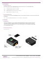
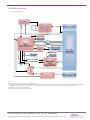
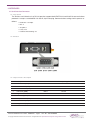
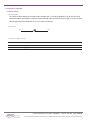
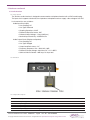
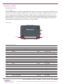
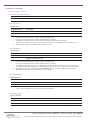
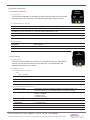
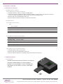
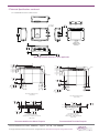
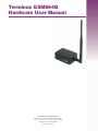
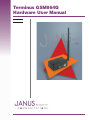
Make Your Communication Boundaries Boundless! Terminus GSM864Q Hardware User Manual Issue: R08 TABLE OF CONTENTS TABLE OF CONTENTS ........................................................................................................................................... 2-3 1 DISCLAIMER .......................................................................................................................................................... 3 2 REFERENCES ........................................................................................................................................................ 4 2.1 Telit Document List 2.2 Janus Document List 3 OVERVIEW .......................................................................................................................................................... 4-6 3.1 Introduction ..................................................................................................................................... 4 3.2 Functional Description ................................................................................................................... 4 3.2.1 Connectors .............................................................................................................................. 4 3.2.2 Block Diagram .......................................................................................................................... 5 3.3 Features .......................................................................................................................................... 6 4 INTERFACES ..................................................................................................................................................... 7-14 4.1 Serial Interface Connector ............................................................................................................. 7 4.1.1 Description 4.1.2 Pin-out 4.1.3 Signal Interface Description 4.2 Power Supply .................................................................................................................................. 8 4.2.1 Description 4.2.2 Pin-out 4.2.3 Power Supply Interface 4.3 Audio Interface ............................................................................................................................... 9 4.3.1 Description 4.3.2 Pin-out 4.3.3 Signal Description 4.4 Embedded Interface ................................................................................................................ 10-12 4.4.1 Description 4.4.2 Pin-out 4.4.3 Signal Description 4.4.4 Signal Detail 4.4.4.1 General Purpose Input / Output 4.4.4.2 Analog to Digital Converter 4.4.4.3 Terminus Control 4.4.4.3.1 Reset Pin 4.4.4.4 ON/OFF Pin 4.4.4.5 PWRMON Pin 4.4.4.6 UART_SEL Pin 4.4.5 Terminus Control Terminus Hardware user Guide - GSM864Q Page 2 Rev: 08 Date: 07/23/08 © Copyright 2008 Janus Remote Communications All Rights Reserved Specifications subject to change without notice 4 INTERFACES continued ................................................................................................................................... 7-14 4.5 LED Status Indicators 4.5.1 Description 4.5.2 GSM 4.5.3 GPS 4.6 RF Interface ............................................................................................................................. 13-14 4.6.1 Description 4.6.2 GSM Antenna 4.6.2.1 GSM Antenna Interface 4.6.2.2 GSM Antenna Specifications 4.6.2.3 GSM Antenna Installation Guidelines 4.6.3 GPS Antenna 4.6.3.1 GPS Antenna Interface 4.6.3.2 GPS Active Antenna Specifications 4.6.3.3 GPS Antenna Installation Guidelines 4.7 SIM Card Interface ....................................................................................................................... 14 4.7.1 Description 4.7.2 Additional details 5 TECHNICAL SPECIFICATIONS ...................................................................................................................... 15-17 5.1 Electrical Specifications .......................................................................................................... 15-16 5.1.1 GSM Module Specifications 5.1.2 GPS Module Specifications 5.1.3 I/O Level Specifications 5.2 GC864Q Mechanical Dimensions ................................................................................................ 17 6. OPERATION ................................................................................................................................................... 18-19 6.1 Setting Up a Terminus Emulator .................................................................................................. 18 6.2 Powering ON/OFF ........................................................................................................................ 18 6.3 Setting Up Network Services ....................................................................................................... 18 6.4 Make a Voice Call ......................................................................................................................... 19 6.5 Making an SMS Call ..................................................................................................................... 19 6.6 Making a GPRS Data Call ............................................................................................................ 19 6.7 Reference to documents .............................................................................................................. 19 7 APPENDICES .................................................................................................................................................. 20-22 7.1 Approvals 7.2 Safety 7.3 Abbreviations 7.4 Ordering Information 7.5 Revision History 1 DISCLAIMER The information contained in this document is the proprietary information of Connor-Winfield Corporation and its affiliates (Janus Remote Communication). The contents are confidential and any disclosure to persons other than the officers, employees, agents or subcontractors of the owner or licensee of this document, without the prior written consent of Connor-Winfield, is strictly prohibited. Connor-Winfield makes every effort to ensure the quality of the information it makes available. Notwithstanding the foregoing, Connor-Winfield does not make any warranty as to the information contained herein, and does not accept any liability for any injury, loss or damage of any kind incurred by use of or reliance upon the information. Connor-Winfield disclaims any and all responsibility for the application of the devices characterized in this document, and notes that the application of the device must comply with the safety standards of the applicable country, and where applicable, with the relevant wiring rules. Connor-Winfield reserves the right to make modifications, additions and deletions to this document due to typographical errors, inaccurate information, or improvements to programs and/or equipment at any time and without notice. Such changes will, nevertheless be incorporated into new editions of this application note. All rights reserved 2007 Connor-Winfield Corporation Terminus Hardware user Guide - GSM864Q Page 3 Rev: 08 Date: 07/23/08 © Copyright 2008 Janus Remote Communications All Rights Reserved Specifications subject to change without notice 2 REFERENCES 2.1 Telit Document List Please refer to Telit’s website at www.telit.com for the latest information on the GC864 GSM module. 2.1.1 1vv0300733 GC864 Hardware User Guide 2.1.2 1vv0300740 GC864 Software User Guide 2.1.3 80000ST10025a AT Commands Reference Guide 2.1.4 80000ST10028 Easy GPRS User Guide 2.2 Janus Document List Please refer to the Janus website, www.janus-rc.com, for the latest product information on the Terminus and the CW20 GPS Module 2.2.1 NavSync CW20/CW20S GPS Receiver User Manual – Bulletin #NS25 3 OVERVIEW 3.1 Introduction The Terminus GSM864Q is a self-contained, quad-band GSM/GPRS terminal device designed to provide a comprehensive solution to application problems for our M2M customers. It utilizes the proven technology of the Telit® GC864-Quad module for its core communications engine as well as the NavSync CW20 module for the added flexibility of GPS. 3.2 Functional Description 3.2.1 Connectors Antenna Connectors Terminus Hardware user Guide - GSM864Q Page 4 Rev: 08 Date: 07/23/08 © Copyright 2008 Janus Remote Communications All Rights Reserved Specifications subject to change without notice 3 OVERVIEW continued 3.2.2 Block Diagram ON/OFF Vgsm VIN Vcc Vmic (3) ON/OFF EXTERNAL GPIO20 ADC GPIO (1-9) RESET PWRMON Vmic GPIO18 / GPS RESET Rx/Tx GPIO19 / GPS WAKEUP (4) (2) (2) (1) Note: 1. RS-232 Signals Include: RxD, TxD, CTS, RTS, DTR, DSR, RING, DCD 2. Only the RxD, TxD and RTS CMOS signals are MIXED between the 50-PIN and DB9 connector. All other UART connections are shared between the 50-PIN and DB9 connector. Hardware Handshaking signals can only be used if either the 50-PIN or DB9 connector is connected exclusively. Shared UART connections are all inputs so no I/O contention will occur. 3. CMOS Signals Include: CTS, DTR, DSR, RING, DCD. 4. Zero Ohm resistor placed only on Python enabled versions. Terminus Hardware user Guide - GSM864Q Page 5 Rev: 08 Date: 07/23/08 © Copyright 2008 Janus Remote Communications All Rights Reserved Specifications subject to change without notice 3 OVERVIEW continued 3.3 Terminus Features 3.3.1 GSM Features Audio Fax Telephony, Emergency Group 3, Class 1 Half rate, Full rate, Enhanced Full rate and GSM Supplementary Adaptive Multi Rate voice codecs (HR, FR, EFR, AMR) Superior Echo Cancellation & Noise Reduction Handset & Hands-free operations Call Forwarding Call Barring Call Waiting & Call Hold Advice of Charge Calling Line Identification Presentation DTMF (Clip) Approvals Calling Line Identification Restriction Fully type approved according to R&TTE CE, GCF, FCC, PTCRB, IC (CLIR) Unstructured Supplementary Services Mobile Originated Data (USSD) SMS Point-to-Point mobile originated and mobile terminal SMS Closed User Group Additional Features Concatenated SMS supported SIM Phonebook SMS Cell Broadcast Fixed Dialing Number (FDN) Text and PDU mode Real Time Clock Circuit Switched Data Transmission Alarm & Battery Management Asynchronous Transparent Circuit Switched Network LED Support Data (CSD) up to 14.4 kbps IRA Character Set Asynchronous Non-transparent CSD up to 9.6 kbps Jamming Detection & Report Embedded TCP/IP Stack, including TP, V.110 IP, UDP, SMTP and FTP protocol GPRS Data GPRS Class 10 Mobile station class B Coding Scheme 1 to 4 PBCCH Support 3.3.2 GPS Features (CW20) Delivers enhanced tracking to -152 dBm Low power consumption: 19mA fully active 16 Channel Receiver Supports WAAS/EGNOS Terminus Hardware user Guide - GSM864Q Page 6 Rev: 08 Date: 07/23/08 © Copyright 2008 Janus Remote Communications All Rights Reserved Specifications subject to change without notice 4 INTERFACES 4.1 Serial Interface Connector 4.1.1 Description The Terminus serial interface is an RS-232 port that supports both EIA/TIA-232 and V.28/V.24 communications protocols. It accepts a standard RS-232 Sub-D, 9-pin male plug. Communications settings for this port are as follows: • Baud Rate: 115.2kbps • Bits: 8 • Stop Bits: 1 • Parity: none • Hardware Handshaking: Yes 4.1.2 Pin-Out 4.1.3 Signal Interface Description Pin Description I/O Signal Type 1 Carrier Detect (CD) OUTPUT RS-232 2 Received Data (RxD) OUTPUT RS-232 3 Transmitted Data (TxD) INPUT RS-232 4 DTE Ready (DTR) INPUT RS-232 5 Signal Ground N/A N/A 6 DCE Ready (DSR) OUTPUT RS-232 7 Request to Send (RTS) INPUT RS-232 8 Clear to Send (CTS) OUTPUT RS-232 9 Ring Indicator (RI) OUTPUT RS-232 Terminus Hardware user Guide - GSM864Q Page 7 Rev: 08 Date: 07/23/08 © Copyright 2008 Janus Remote Communications All Rights Reserved Specifications subject to change without notice 4 Interfaces continued 4.2 Power Supply 4.2.1 Description The Terminus Power Supply jack accepts input voltages from 7 to 18 VDC (optionally 7 to 40 VDC for V3.00 and V4.00 models) and requires a nominal current sourcing capacity of 5W (maximum 10W). This jack accepts a barrel type plug with a receptacle for a 2.1mm center conductor. 4.2.2 Pin Out (-) (+) 4.2.3 Power Supply Interface Pin Description Center Pin Supply (+) Outer Conductor Supply (-) Terminus Hardware user Guide - GSM864Q Page 8 Rev: 08 Date: 07/23/08 © Copyright 2008 Janus Remote Communications All Rights Reserved Specifications subject to change without notice 4 Interfaces continued 4.3 Audio Interface 4.3.1 Description The Terminus audio interface is designed to accommodate a telephone handset with a 4P4C modular plug. The input circuit supports a balanced, low-impedance microphone and can supply a bias voltage of 3.0 VDC. Its characteristics are as follows: Audio Input Circuit (Mic) • Line Coupling: AC • Line Type: Balanced • Coupling Capacitor: ≥100nF • Differential Input Resistance: 50kΩ • Differential Input Voltage: ≤1Vp-p (365Vrms) • Nominal Input Sensitivity: -45 dBVrms/Pa Audio Output Circuit (Earpiece or Speaker) • Line Coupling: DC • Line Type: Bridged • Output Load Resistance: ≥14Ω • Frequency Response: 150 – 4000 Hz @ -3dB • Differential Output Voltage: 328mVrms/16Ω @ -12 dBFS • Software Volume Control: -2dB/step, 10 steps total 4.3.2 Pin-Out 4.3.3 Signal Description Pin Description 1 Microphone (-) 2 Earphone (-) 3 Earphone (+) 4 Microphone (+), 3.0Vdc nominal supplied by Terminusto power handset. Terminus Hardware user Guide - GSM864Q Page 9 Rev: 08 Date: 07/23/08 © Copyright 2008 Janus Remote Communications All Rights Reserved Specifications subject to change without notice 4 Interfaces continued 4.4 Embedded Interface 4.4.1 Description The Embedded Interface is a 50 pin straight header that allows a user to access many of the available ports and features of the Terminus through a single interface. The connector is located on the bottom of the unit such that it can be integrated with an application PC board. A ribbon cable with a tabbed header connector such as the Samtec HCSD-25-D-1 can also be used. This interface can be functionally divided up into the following groups: General Purpose I/O interface, the ADC interface, Terminus Control interface and GPS Receiver interface. The pin designations and specifications for this interface are shown below. 4.4.2 Pin-Out Bottom View Pin 1 Pin 49 Pin 50 Pin 2 4.4.3 Signal Description Pin Description I/O Signal Type 1 3.165 Vdc Output (refer to Supply Specification) OUTPUT N/A 3 RESET INPUT Internal Pull-up 5 ON/OFF INPUT Internal Pull-up 7 PWRMON OUTPUT 2.8V_CMOS 9 UART_SEL INPUT 2.8V_CMOS 11 ADC1 INPUT ANALOG 13 GPIO1 BI-DIR 2.8V_CMOS 15 GPIO2 BI-DIR 2.8V_CMOS 17 GPIO3 BI-DIR 2.8V_CMOS 19 GPIO4 BI-DIR 2.8V_CMOS 21 GPIO5 BI-DIR 2.8V_CMOS 23 GPIO6 BI-DIR 2.8V_CMOS 25 GPIO7 BI-DIR 2.8V_CMOS 27 GPIO8 BI-DIR 2.8V_CMOS 29 GPIO9 BI-DIR 2.8V_CMOS 31 DCE Ready (DSR) OUTPUT 2.8V_CMOS 33 Clear to Send (CTS) OUTPUT 2.8V_CMOS Terminus Hardware user Guide - GSM864Q Page 10 Rev: 08 Note 1 Date: 07/23/08 © Copyright 2008 Janus Remote Communications All Rights Reserved Specifications subject to change without notice 4 Interfaces continued 4.4.3 Signal Description continued Pin Description I/O Signal Type 35 Ring Indicator (RI) OUTPUT 2.8V_CMOS 37 Carrier Detect (CD) OUTPUT 2.8V_CMOS 39 DTE Ready (DTR) INPUT 2.8V_CMOS 41 Request to Send (RTS) INPUT 2.8V_CMOS 43 GPS_RxD INPUT 2.8V_CMOS 45 Received Data (RxD) OUTPUT 2.8V_CMOS 47 GPS_TxD OUTPUT 2.8V_CMOS 49 Transmitted Data (TxD) INPUT 2.8V_CMOS 2,4,6,8 Supply (+) (7 - 18 VDC) N/A N/A N/A N/A 10,12,14,16,18, Supply (-) (GND) 20,22,24,26,28, 30,32,34,36,38, 40,42,44,46,48,50 Note 2 2 Notes: 1. It is recommended that this input be controlled by an Open Collector/Drain output. Do not use an external pull-up resistor, a pull-up is included internal to the Terminus. 2. This signal is only available by option, otherwise No Connection. 4.4.4 Signal Details 4.4.4.1 General Purpose Input / Output Terminus GPIO are configurable as input, output, and special function. Configuration is controlled by the Customer specific application via AT commands send on the UART interface. The following table describes GPIO configuration options. GPIO Configuration 1 Input / Output 2 Input / Output 3 Input / Output 4 Input / Output 5 Input / Output RFTX monitor output 6 Input / Output alarm output 7 Input / Output buzzer output 8 Input / Output 9 Input / Output Terminus Hardware user Guide - GSM864Q Alternate Function Page 11 Rev: 08 Date: 07/23/08 © Copyright 2008 Janus Remote Communications All Rights Reserved Specifications subject to change without notice 4 Interfaces continued 4.4.4 Signal Details continued 4.4.4.2 Analog to Digital Converter ADC Description 1 Analog to Digital Converter Input 4.4.4.3 Reset Pin RESET PIN: Input Logic State Description High-Z Terminus Active State 0 Terminus Reset State Notes: 1. 2. 3. It is recommended that this input be controlled by an Open Collector/Drain output. Do not use an external pull-up resistor, a pull-up is included internal to the Terminus. The RESET pin is offered as a means to reset the Terminus when and if the Terminus becomes unresponsive. The RESET pin is not intended to be used as a means of turning the Terminus off. Use the ON/OFF pin to turn the Terminus on or off. RESET state must be held for at least 200ms before returning to active state. 4.4.4.4 ON/OFF Pin ON/OFF PIN: Input Logic State Description High-Z Terminus turned ON or OFF after Input returns to this state. 0 Toggle Terminus ON or OFF Notes: 1. 2. 3. 4. It is recommended that this input be controlled by an Open Collector/Drain output. Do not use an external pull-up resistor, a pull-up is included internal to the Terminus. The ON/OFF pin is offered as a means to power-on and power-down the Terminus. When the Terminus powers-down it informs the cell tower that it is powering down and will not be communicating with the tower any more. This is considered a controlled power-down. After toggling the power state of the Terminus, wait until PWRMON indicates chosen state before toggling the power state again. Optionally the Terminus may be powered-down with the use of AT commands. 4.4.4.5 PWRMON Pin PWRMON PIN: Output Logic State Description 0 Terminus powered-down 1 Terminus powered-on Notes: 1. Used in conjunction with ON/OFF pin to control power-on and power-down state. 4.4.4.6 UART_SEL Pin UART_SEL PIN: Input Logic State Description 1 Terminus UART interface routed to DB9 connector (RS-232) 0 Terminus UART interface routed to EMBEDDED connector (2.8V_CMOS) Terminus Hardware user Guide - GSM864Q Page 12 Rev: 08 Date: 07/23/08 © Copyright 2008 Janus Remote Communications All Rights Reserved Specifications subject to change without notice 4 Interfaces continued Status Indicator 4.5 LED Status Indicators 4.5.1 Description The LED Status Indicators are located on the top of the housing near the end where the antenna jacks are. There are 2 LED indicators; GSM Status and GPS Status. GPS LED GSM LED 4.5.2 GSM LED Status (Yellow) LED Status Device Status Permanently Off Device Off Fast Blinking (0.5 sec on/0.5 sec off) Net search/ Not registered/Turning Off Slow Blinking (0.3 sec on/ 2.7 sec off) Registered, Full Service Permanently On A call is active 4.5.3 GPS (Green) LED Status Device Status Permanently Off Device Off Blinking Receiver Activated RF Interface 4.6 RF Interface 4.6.1 Description There are two RF interfaces on the Terminus – the GSM antenna jack and the GPS antenna jack (the non-GPS version will only have one). The specifications and requirements for these are as follows: GPS GSM Jack Jack 4.6.2 GSM Antenna 4.6.2.1 GSM Antenna Interface: Type: SMA - FEMALE Pin Center Pin Description GSM Signal Outer Conductor SIGNAL Ground 4.6.2.2 GSM Antenna Specifications Frequency range Depending by frequency band(s) provided by the network operator, the customer shall use the most suitable antenna for that/those band(s) Bandwidth 70 MHz in GSM850 80 MHz in GSM900 170 MHz in DCS 140 MHz PCS band Gain < 3dBi Impedance 50 ohm Input power > 2 W peak power VSWR (absolute max) <= 10:1 VSWR (recommended) <= 2:1 Terminus Hardware user Guide - GSM864Q Page 13 Rev: 08 Date: 07/23/08 © Copyright 2008 Janus Remote Communications All Rights Reserved Specifications subject to change without notice 4 Interfaces continued 4.6 RF Interface continued 4.6.2 GSM Antenna continued 4.6.2.3 GSM Antenna Installation Guidelines 1. Install the antenna in a place covered by the GSM signal. 2. The Antenna must be installed to provide a separation distance of at least 20 cm from all persons and must not be co-located or operating in conjunction with any other transmitting antenna. 3. Antenna shall not be installed inside metal cases. 4. Antenna shall be installed according to manufacturer instructions. 4.6.3 GPS Antenna 4.6.3.1 GPS Antenna Interface Type: MCX - FEMALE Pin Center Pin Description GPS Signal, 3.7 Vdc nominal supplied from Terminus to power active antenna. Outer Conductor Signal ground Note: GPS Antenna Interface only available by option, otherwise not populated. 4.6.3.2 GPS Active Antenna Specifications: Input Voltage Range 3.4 to 4.2 Vdc Frequency range 1575.42 ± 3 MHz Gain Depends on cable type and length Impedance 50 ohm VSWR <= 1.5:1 Note: GPS Antenna Interface only available by option, otherwise GPS Antenna not required. 4.6.3.3 GPS Antenna Installation Guidelines 1. Install the antenna with a clear sky view. 2. Antenna shall not be installed inside metal cases. 3. Antenna shall be installed also according to Antenna manufacturer instructions. 4.7 SIM Card Interface 4.7.1 Description The SIM Card Interface allows the Terminus to accept the subscriber card provided by the cellular telephone provider. It can accommodate a 1.8V or 3.0V SIM card and complies with the GSM 11.14 Phase 2 SIM Toolkit standard. Terminus Hardware user Guide - GSM864Q Page 14 Rev: 08 Date: 07/23/08 © Copyright 2008 Janus Remote Communications All Rights Reserved Specifications subject to change without notice 5 TECHNICAL SPECIFICATIONS 5.1 Electrical Specifications 5.1.1 GSM Module Specification • Quad-band EGSM 850 / 900 / 1800 / 1900 MHz • Output Power: Class 4 [2W] @ 850 / 900 MHz, Class 1 [1W] @ 1800 / 1900 MHz • Control via AT commands according to GSM 07.05, 07.07 and proprietary Telit • Serial Port Multiplexer GSM 7.10 • TCP/IP stack access via AT commands • Sensitivity: -107 dBm (type.) @ 850 / 900 MHz, -106 dBm (typ.) @ 1800 / 1900 MHz 5.1.2 GPS Module Specifications GPS Channels 16 Frequency 1575.42 MHz – L1 C/A Code TTFF Cold Start @ -135 dBm 46 seconds 1, 7 TTFF Warm Start @ -141 dBm 34 seconds 1, 7 TTFF Hot Start @ -141 dBm 5 seconds 1, 7 Re-acquisition time @ -147 dBm <3 seconds 2 Acquisition Sensitivity (fix not available) TTFF (Hot) with all signals at -138 dBm: 30 s TTFF (Hot) with all signals at -141 dBm: 41 s 3 Acquisition Sensitivity (fix available) (dBm) -147 dBm 4 Tracking Sensitivity (dBm) -150 dBm 5 Acquisition Sensitivity SBAS satellites (dBm) -135 dBm -143 dBm 6 Static Accuracy (without SBAS) 50% Confidence (CEP) 95% Confidence 1.2 m 3.1 m 7 Static Accuracy (with SBAS) 50% Confidence (CEP) 95% Confidence 0.8 m 2.0 m 8 Maximum Horizontal Speed 515 m/s 9 Maximum Vertical Speed 15 m/s 10 Maximum Altitude 18 Km 11 Maximum Acceleration (g) 2g Notes: 1. 2. 3. 4. 5. 6. These are RMS values Maximum Sensitivity -147 dBm Simulator Test, all signals at specified power level. Estimated Simulator Test, continuous fix with all signals at specified power level. Simulator Test with signal at specified power level. Terminus Hardware user Guide - GSM864Q Page 15 Rev: 08 7. Open-sky, 24 hrs statistic, active antenna (signal range is between 30 to 49 dB/Hz). 8. Open sky, 24 hrs statistic, active antenna (EGNOS signal used). 9. Limited by International Traffic in Arms Regulation (ITAR) 10. Defined by navigation integrity check 11. Limited by International Traffic in Arms Regulation (ITAR) Date: 07/23/08 © Copyright 2008 Janus Remote Communications All Rights Reserved Specifications subject to change without notice 5 Technical Specifications continued 5.1.3 I/O Level Specification Absolute Maximum Ratings Parameter Min Typ Max Unit VIN (DIGITAL INPUTS) -0.3 - +3.75V Volt VIN (ANALOG INPUT) -0.3 - +3.00V Volt Storage Temperature -40 - 85 °C 0 - 24 V Supply (+) referenced to Supply(-) Note 1 Operation of the device at these or any other conditions beyond those listed under Recommended Operating Conditions is not implied. Exposure to Absolute Maximum Rating conditions for extended periods of time may affect device reliability. Recommended Operating Conditions Parameter Min Typ Max Unit Note Temperature -10 - 55 °C Supply (+) referenced to Supply (-) 7 - 18V Volt 1 3.165 VDC Output 3 - 3.3V Volt 2 Recommended Operating Conditions - Interface levels (2.8V CMOS) Parameter Min Typ Max Unit Input Voltage High - Vih 2.1 - 3.3 Volt Input Voltage Low - Vil 0 - 0.5 Volt Output Voltage High - Voh 2.2 - 3.0 Volt Output Voltage Low - Vol 0 - 0.35 Volt Typical Current Source/Sink capability = 1mA/1uA Recommended Operating Conditions - RESET pin Parameter Min Typ Max Unit Input Voltage High - Vih_rst 2.0 - 2.2 Volt Input Voltage Low - Vil_rst 0 - 0.2 Volt It is recommended that this input be controlled by an Open Collector/Drain output. Do not use an external pull-up resistor, a pull-up is included internal to the Terminus. Recommended Operating Conditions - ADC1 pin Parameter Min Typ Max Unit Input Voltage Range 0 - 2 Volt AD Conversion - - 11 Bits Resolution 1 1 <1 mV Min Typ Max Unit 7 - 18 VDC 5.1.4 Terminus Electrical Specifications Power Supply Voltage Range Note Current (idle mode) 14 - 22 mA (typ) 3 Current (idle mode) with GPS 20 - 35 mA (typ) 3, 4 11.5 Watts 5 Power (max) Note: 1. 7-40V Vin by option. Please contact a sales representative for more information about ordering Terminus with GPS option. 2. Max current draw of 25mA on the 3.165VDC output. 3. Registered on Network, No Traffic 4. Active antenna not connected. 5. Maximum power during GSM transmission (see Telit GC864 Hardware User Guide, Section 5.1 for more information) Terminus Hardware user Guide - GSM864Q Page 16 Rev: 08 Date: 07/23/08 © Copyright 2008 Janus Remote Communications All Rights Reserved Specifications subject to change without notice 5 Technical Specifications continued 5.2.3 GC864Q Mechanical Dimensions 2x Hole for #6 SHCS .650 16.51 2.600 66.04 Bottom View w/ Bottom Cover Removed 1.214 30.84 3.750 95.25 .313 7.95 Mounting GC864Q Terminus in your application 2.600 66.04 2.369 60.18 2.357 59.86 2.600 66.04 PIN 1 2.369 60.18 2.304 58.52 2.152 54.65 2.143 54.44 2.050 52.07 2.204 55.98 2.143 54.44 Pin 1 2.050 52.07 .550 13.97 .550 13.97 0 0 Mechanical Dimensions (Top View) .070 1.78 Mechanical Dimensions (Top View) 2.400 60.96 2.400 60.96 Pin #50 Pin #50 Pin #2 Pin #49 Pin #1 .100 2.54 Pin #2 Pin #49 Pin #1 .040 1.02 .050 1.27 .100 2.54 .340 8.64 3.750 95.25 3.075 78.11 3.228 82 3.375 85.73 .675 17.15 .375 9.53 .140 3.56 2x (Clearance for a #6 SHCS .522 13.25 0 0 3.750 95.25 3.228 82 3.375 85.73 3.075 78.11 .675 17.15 .522 13.25 0 0 .375 9.53 0 0 .140 3.56 2x (Clearance for a #6 SHCS) .100 2.54 Hole Dimensions for recomended connector, Samtec P/N SSQ-125-XX-X-D (Top View) Pad Dimensions for recomended connector, Samtec P/N SSW-125-22-S-D-VS (Top View) Recommended Surface Mount Footprint Terminus Hardware user Guide - GSM864Q Page 17 Recommended Thru-Hole Footprint Rev: 08 Date: 07/23/08 © Copyright 2008 Janus Remote Communications All Rights Reserved Specifications subject to change without notice 6. OPERATION 6.1 Setting Up a Terminus Emulator 6.1.1 To interface with the Terminus connect the Serial Interface RS-232 port to a PC and use a terminal emulation program such as Microsoft® Hyperterminal. Set the interface parameters as follows: • Baud Rate: 115.2 kbps • Bits: 8 • Stop Bits: 1 • Parity: None • Hardware Handshaking: Yes 6.1.2 Set Terminus to Auto-bauding • Enter AT<cr> from terminal and wait for OK • Enter AT+IPR=0<cr> and wait for OK • Terminus is now set for auto data rate detection 6.2 Powering ON/Off 6.2.1 The Terminus is turned ON automatically once DC power is applied. If the Terminus is turned OFF using one of the methods described below, it can be turned back ON again through one of two methods: • pull ON/OFF signal (pin 3 of 50 pin straight header) to ground, then release. • press the ON/OFF switch, then release The Terminus is fully operational after 4 seconds. Logging onto a network may take longer than this and is outside the control of the Terminus. 6.2.2 There are three ways to switch OFF the Terminus as described below. • Use the appropriate AT command (AT#SHDN) • Pull ON/OFF signal to ground, then release • Press ON/OFF switch (SW1), then release 6.3 Setting Up Service – Network Settings 6.3.1 The network settings for the Terminus will vary depending on the cellular carrier you are using. Below are two of the North American Cases for these settings. For T-mobile® & MNVO (Raco®, Sensor Logic®, Nexaira® Jasper Wireless®) enter: AT#SELINT=2 //use of most recent AT command set AT#STIA=2,10 or AT#STIA=1 // enable SAT – SIM Application Tool-Kit AT#BND=3 // default bands to 850/1900 AT#AUTOBND=1 // enable Quad band system selection AT#PLMNMODE=1 // enable EONS (enhanced operator naming scheme) AT&P0 // save profile AT&W0 // save setting For AT&T/Cingular® & MNVO (Kore®, Aeris®, nPhase®) enter: AT#SELINT=2 //use of most recent AT command set AT#ENS=1 // AT&T/Cingular configuration (SAT, BND, AUTONBND, PLMNMODE, plus Cingular® specific ENS requirements) If Terminus is being used in a different country or with a different carrier please refer to Telit AT Command reference document regarding the use of the AT#BND command to set the proper frequency band). Important: After entering either of the sets of settings above power the Terminus OFF and then ON. It is now ready for use. 6.3.2 Check network status (assuming you have a valid SIM card installed) Enter AT+CREG? <cr> And wait for response Response will be +CREG:0,1 or +CREG:1,1 meaning device is registered on its home network. If response is different than this please refer to the Telit AT Command Reference document for more information. 6.3.3 Check signal quality Enter AT+CSQ<cr> And wait for response +CSQ:<rssi>,<ber> Terminus Hardware user Guide - GSM864Q Page 18 Rev: 08 Date: 07/23/08 © Copyright 2008 Janus Remote Communications All Rights Reserved Specifications subject to change without notice 6. OPERATION continued 6.4 Making a Voice Call 6.4.1 Voice call mode allows you to use a telephone handset to communicate with a properly equipped subscriber unit. • To set the call mode to voice enter AT+FCLASS=8<cr> and wait for response OK • To set the audio path of the Terminus to internal (for handset use) enter AT#CAP=2 • To dial the phone number enter ATD <8885551234>; <cr> • To disconnect the call enter ATH<cr> 6.5 Making an SMS Call 6.5.1 SMS (Select Message Service) mode allows you to send a text message (max 160 characters) to a SMS capable subscriber unit. • To set the message mode to text enter AT+CMGF=1<cr> • To enter the receiving subscriber unit phone number and message enter: 1. AT+CMGS=<8885551234> 2. Wait for response”>” then enter message text 3. Enter “ctrl z” <cr> to end message 6.6 Making a GPRS Data call 6.6.1 GPRS is a data service that uses Packet Data Protocol (PDP). • To set up the PDP context parameters enter: AT+CGDCONT=1, “IP”, “APN”, “0.0.0.0”,0,0<cr> where APN is specific to the service provider being used. • Enter AT+CGQMIN=1,0,0,0,0,0 1. This sets the minimum Quality of Service profile • Enter AT+CGQREQ=1,0,0,3,0,0 1. This sets up the desired Quality of Service profile • Enter AT#SGACT=1,1,”v”, “p” where v is your user ID and p is your password. If these are not set replace with “”,”” 1. This activates the PDP context • Enter AT#SD=1,0,IPA, “Port”,0,0 1. Look for response “CONNECT”. This opens a remote connection via socket 2. IPA = the IP address given to you by your service provider in the format: “xxx.xxx.xxx.xxx” 3. ‘Port’= the remote host port to contact provided by carrier (0 to 65535) • At this point a data session is active and data can be sent from the Terminus to the remote device and visa versa. 1. To exit the data session send the characters”+++” and wait for the OK response • Enter AT#SH=1 to close the socket 6.7 Further Instructions On utilizing different commands for other applications than those described here, please refer to the following documents: Telit AT Commands Reference Guide Telit GC864 Software User Guide Telit Easy GPRS User Guide Terminus Hardware user Guide - GSM864Q Page 19 Rev: 08 Date: 07/23/08 © Copyright 2008 Janus Remote Communications All Rights Reserved Specifications subject to change without notice 7 APPENDICES 7.1 Approvals 7.1.1 PTCRB Certification The Terminus is PTCRB Certified; Lab: Cetecom, Inc.; Date: 7/27/2007 7.2 Safety Recommendations (for Information only) 7.2.1 General Your Terminus GSM864Q (Terminus) terminal is based on the GSM standard for cellular technology. This standard is universal and covers Europe, Asia, United States and Africa which is the most used telecommunication standard. Your Terminus is a low power radio transmitter and receiver. It sends out and receives radio frequency energy. When a GSM application is used, the cellular system that handles your calls controls both the radio frequency and the power level of your cellular wireless CPU®. 7.2.2 Exposure to RF Energy There is public concern about possible health effects of using GSM terminals. Although past research on health effects from RF energy has focused on the current RF technology, scientists have begun researching newer radio technologies, such as GSM. After existing research has been reviewed, and after compliance to all applicable safety standards has been tested, the conclusion is that the product is fit for use. 7.1.3 Antenna Care and Replacement Do not use the Terminus with a damaged antenna. If a damaged antenna comes into contact with the skin, a minor burn may result. If you have a damaged antenna, refer to the instruction manual provided for proper procedures. Or, have your antenna repaired by a qualified technician. Buy the antenna from an approved suppliers list. Using unauthorized antennas, modifications, or attachments could damage the Terminus and may violate local RF emission regulations or invalidate type approval. 7.3 Abbreviations AC Alternating Current GSM Global System Mobile ADC Analog To Digital Converter ITAR International Traffic In Arm Regulation BER Bit Error Rate LED Light Emitting Diode CD Carrier Detect M2M Machine To Machine CSD Circuit Switched Data PBCCH Packet Broadcast Control Channel CTS Clear To Send PDU Protocol Data Unit DB Decibel RF Radio Frequency DBFS Decibels Full Scale RI Ring Indicator DC Direct Current RSSI Received Signal Strength Indication DCE Data Communications Equipment RTS Request To Send DSR Data Set Ready RxD Received Data DTMF Dual-tone multi-frequency SMS Short Message Service DTR DTE Ready TTFF Time To First Fix EGNOS European Geostationary Navigation Overlay Service TxD Transmitted Data FDN Fixed Dialing Number USSD Unstructured Supplementary Service Data GPIO General Purpose Input Output VSWR Voltage Standing Wave Ratio GPRS General Packet Radio Service WAAS Wide Area Augmentation System Terminus Hardware user Guide - GSM864Q Page 20 Rev: 08 Date: 07/23/08 © Copyright 2008 Janus Remote Communications All Rights Reserved Specifications subject to change without notice 7. APPENDICES continued 7.4 Ordering Information Ordering Information Description GSM864Q V1.00 Terminus GPS Terminal GSM864Q V2.00 Terminus Non-GPS Terminal GSM864Q V3.00 Terminus GPS Terminal HV GSM864Q V4.00 Terminus Non-GPS Terminal HV GSM864QP V1.00 Terminus GPS Terminal w/Python * GSM864QP V2.00 Terminus Non-GPS Terminal w/Python * GSM864QP V3.00 Terminus GPS Terminal HV w/Python * GSM864QP V4.00 Terminus Non-GPS Terminal HV w/Python * * Note disclaimer: The Python enabled terminals are not PTCRB or carrier certified 7.5 Revision History Revision Revision Date Note V 1.0 04/18/07 Preliminary Manual V 2.0 06/26/07 Added Mechanical Drawings V 3.0 06/28/07 Added Order Information & Spec Corrections V 4.0 08/23/07 Updated Mechanical Drawings V 5.0 10/23/07 Update Content and Additions R06 02/18/08 Updated Block Diagram and Revision Control R07 04/11/08 Pin-Out Correction R08 07/23/07 Approvals, Abbreaviations, Revisions Terminus Hardware user Guide - GSM864Q Page 21 Rev: 08 Date: 07/23/08 © Copyright 2008 Janus Remote Communications All Rights Reserved Specifications subject to change without notice Terminus GSM864Q Hardware User Manual Janus Remote Communications Division of The Connor-Winfield Corporation 2111 Comprehensive Drive • Aurora, Illinois 60505 630.499.2121 • Fax: 630.851.5040 www.janus-rc.com