1
MIKADO
User Manual
Lighting Technologies
ME 1133
1106.01.133
MIKADO USER MANUAL
CONTENT
CONTENT ............................................................................................................................................... 1 1. INTRODUCTION ............................................................................................................................ 3 1.1 Delivery and Unpacking ......................................................................................................... 3 1.2 Preparing the Desk Location .................................................................................................. 3 1.3 MIKADO ................................................................................................................................. 3 1.4 Power Supply ......................................................................................................................... 4 1.5 Electrical Connection ............................................................................................................. 4 1.6 FEATURES ............................................................................................................................ 4 1.7 OPTIONS ............................................................................................................................... 5 1.8 CARING FOR YOUR MIKADO .............................................................................................. 5 1.9 TERMINOLOGY ..................................................................................................................... 5 1.9.1 CHANNEL .......................................................................................................................... 6 1.9.2 LOOK ................................................................................................................................. 6 1.9.3 PRESET............................................................................................................................. 6 1.9.4 PRESET MASTER ............................................................................................................ 6 1.9.5 GRAB MASTER ................................................................................................................. 6 1.9.6 MEMORY ........................................................................................................................... 6 1.9.7 CHASER ............................................................................................................................ 6 1.9.8 PLAY BACK ....................................................................................................................... 6 1.10 SOFTWARE ........................................................................................................................... 7 2. GETTING CONNECTED ................................................................................................................ 8 2.1 2.2 MAINS INPUT ........................................................................................................................ 8 DMX512 OUTPUT ................................................................................................................. 8 3. FRONT PANEL LAYOUT .............................................................................................................. 9 4. MODES OF OPERATION ............................................................................................................ 10 4.1 OVERVIEW .......................................................................................................................... 10 4.2 A / B MODE .......................................................................................................................... 10 4.3 WIDE MODE ........................................................................................................................ 10 4.4 Memory MODE .................................................................................................................... 11 4.5 FADE TIMES ........................................................................................................................ 11 4.5.1 MASTERS........................................................................................................................ 11 4.5.2 SUBMASTERS ................................................................................................................ 11 4.5.3 MEMORIES ..................................................................................................................... 12 4.5.4 CHASERS........................................................................................................................ 12 4.5.5 CHANNELS ..................................................................................................................... 12 4.6 MEMORY RUN .................................................................................................................... 12 4.7 MEMORY PREVIEW ........................................................................................................... 12 4.8 MEMORY EDIT .................................................................................................................... 13 4.9 MODE/PAGE FREEZE ........................................................................................................ 13 4.10 FADER MATCHING/CAPTURE .......................................................................................... 13 5. MEMORIES .................................................................................................................................. 14 5.1 OVERVIEW .......................................................................................................................... 14 5.2 RECORDING A MEMORY................................................................................................... 14 5.2.1 RECORDING FADE TIMES ............................................................................................ 14 5.2.2 ABANDONING A RECORDING ...................................................................................... 15 5.2.3 BLIND RECORDING ....................................................................................................... 15 5.3 SUBMASTER A MEMORY .................................................................................................. 15 5.4 PREVIEW A MEMORY ........................................................................................................ 15 5.5 EDIT A MEMORY ................................................................................................................ 16 5.5.1 ADJUSTING CHANNEL LEVELS.................................................................................... 16 5.5.2 ADJUSTING FADE TIMES .............................................................................................. 16 www.adblighting.com
User Manual - page 1
Issue 1.0
MIKADO USER MANUAL
5.6 6. DELETE A MEMORY........................................................................................................... 17 CHASERS .................................................................................................................................... 18 6.1 OVERVIEW .......................................................................................................................... 18 6.2 RECORDING A CHASER .................................................................................................... 18 6.2.1 RECORDING THE SPEED (RATE) ................................................................................ 19 6.2.2 RECORDING THE CROSSFADE TIME ......................................................................... 19 6.2.3 RECORDING DIRECTION MODE AND TRIGGER EFFECTS ...................................... 20 6.3 SUBMASTER A CHASER ................................................................................................... 20 6.3.1 CONTROLLING A CHASER ........................................................................................... 20 6.4 PREVIEW A CHASER ......................................................................................................... 21 6.5 EDIT A CHASE .................................................................................................................... 22 6.5.1 TO EDIT THE CHANNEL LEVELS OF A STEP IN A CHASER ..................................... 22 6.5.2 TO EDIT THE EFFECTS IN A CHASER ......................................................................... 22 6.5.3 TO CHANGE DIRECTION OF A CHASER ..................................................................... 22 6.5.4 TO CHANGE PATTERN OF A CHASE ........................................................................... 22 6.5.5 TO ACTIVATE EXTERNAL TRIGGER TO RUN A CHASE ............................................ 23 6.5.6 TO ACTIVATE AUDIO INPUT TO RUN A CHASE ......................................................... 23 6.5.7 TO ADD A STEP IN A CHASE ........................................................................................ 23 6.5.8 TO DELETE A STEP IN A CHASER ............................................................................... 23 6.5.9 TO CHANGE THE SPEED OF A CHASER .................................................................... 23 6.5.10 TO CHANGE THE CROSSFADE TIME OF A CHASER ............................................ 23 6.6 DELETE A CHASER ............................................................................................................ 23 7. GRAB MASTER ........................................................................................................................... 24 7.1 7.2 7.3 7.4 8. FLASH .......................................................................................................................................... 26 8.1 8.2 8.3 9. Overview .............................................................................................................................. 24 GRAB MASTER AS A MEMORY MASTER ........................................................................ 24 GRAB MASTER AS A CHASER MASTER.......................................................................... 24 GRAB MASTER AS A PHANTOM PRESET MASTER ....................................................... 24 OVERVIEW .......................................................................................................................... 26 ADD/SOLO MODE ............................................................................................................... 26 FLASH/LEVEL ..................................................................................................................... 26 UTILITIES ..................................................................................................................................... 27 9.1 RESET ................................................................................................................................. 27 9.1.1 SOFT RESET .................................................................................................................. 27 9.1.2 HARD RESET .................................................................................................................. 27 9.2 EXTERNAL MEMORY MODULE ........................................................................................ 27 9.2.1 SAVE SHOW TO MEMORY MODULE ........................................................................... 27 9.2.2 LOAD SHOW FROM MEMORY MODULE ..................................................................... 28 9.3 AUDIO INPUT ...................................................................................................................... 28 9.4 EXTERNAL TRIGGER INPUT ............................................................................................. 29 10. COMPLIANCE STATEMENTS .................................................................................................... 30 10.1 10.2 CE COMPLIANCE STATEMENT ........................................................................................ 30 DISCLAIMER ....................................................................................................................... 30 11. MIKADO QUICK REFERENCE ................................................................................................... 31 11.1 11.2 11.3 11.4 11.5 RECORD A MEMORY ......................................................................................................... 31 GRAB THE OUTPUT IN GRAB MASTER ........................................................................... 31 RECORD A CHASER .......................................................................................................... 31 SUBMASTER A MEMORY OR CHASER............................................................................ 31 EDIT A MEMORY OR CHASER .......................................................................................... 32 User Manual - page 2
Issue 1.0
www.adblighting.com
MIKADO USER MANUAL
1. INTRODUCTION
1.1 Delivery and Unpacking
As soon as you receive your equipment, open the boxes and inspect the items received. If
you discover any damage, contact the carrier immediately and make any necessary claim for
the problems discovered.
The equipment was checked before being packed and left our factory in perfect condition.
Check that the equipment supplied to you corresponds to the consignment note and that this
corresponds to your order. You will find the references of your desk on an identification label
affixed to the rear panel.
If there is any discrepancy in the order and delivery, contact your supplier immediately who
will clarify the situation to your full satisfaction.
Permissible storage conditions:
Temperature : -10 to +50° C
: variation rate: 20°/hour.
Relative humidity: 20 to 80 % without condensation.
1.2 Preparing the Desk Location
The surface of your work area should be smooth, level and sturdy.
Make sure that there is enough clearance around the desk to:
• open the desk
• access the rear connections
• allow air circulation around vents to prevent the desk from over-heating.
1.3 MIKADO
The MIKADO desk is a professional lighting console, it is Class I equipment designed and
manufactured to the EN60950 standard. THIS EQUIPMENT MUST BE EARTHED.
No special undertaking need to be made for the installation of the equipment. The room in
which the equipment is to be installed must be clean, dust-free and have a temperature
between 5 and 35° C and a relative humidity from 20 to 80 % without condensation.
Consumption of food and drink over the desk is inadvisable to avoid it being accidentally
dropped into the equipment and impairing certain functions.
The desk and the monitor should be installed on a table or a console. Like all equipment that
includes microprocessors and uses similar technology, the desk is sensitive to the influences
of static electricity and it is possible that these influences will affect functioning in certain
circumstances. If this is the case, it will be necessary to place anti-static carpets on the floor
and perhaps to make the atmosphere more humid. Whenever a carpet is to be used, it must
be an antistatic carpet.
In order to avoid wasting time and possibly damaging the equipment, the installer is invited to
scrupulously follow the instructions in the diagrams shown, and on the rear panel of the ISIS
based desk.
Before powering up the desk or any of its peripherals, check that the existing voltages are
within the limits defined in the TECHNICAL SPECIFICATIONS paragraph.
www.adblighting.com
User Manual - page 3
Issue 1.0
MIKADO USER MANUAL
Note: all connections should be made with the power turned off, otherwise functioning may
be affected and can even damage the equipment under certain conditions.
1.4 Power Supply
As all equipment used in computer systems, your system is sensitive to the characteristics of
the network and in particular to variations and voltage peaks.
Consequently, we advise you to use an appropriate line conditioner on this equipment.
Please consult us if you are in any doubt about this.
The line is to be protected by fuse or by circuit breakers and is to be provided with an earth
connection for personal safety.
Important Notice for Power Cables
Power cables and connectors are an important part of your equipment and contribute to its
safety.
Always use the connector to make or interrupt the link; never pull on the cable.
Do not damage the cable or the connectors in any way; do not pinch or tie together power
supply and signal cables, check them at each installation and at regular intervals on a
permanent installation.
1.5 Electrical Connection
TO PREVENT THE RISK OF ELECTRIC SHOCK, DO NOT OPEN THE DESK.
THERE ARE NO USER SERVICEABLE PARTS WITHIN. REFER SERVICING TO
QUALIFIED ENGINEERS ONLY. LETHAL VOLTAGES ARE PRESENT INSIDE!
ALWAYS DISCONNECT FROM THE POWER SUPPLY BEFORE OPENING FOR
INSPECTION.
MIKADO is a professional lighting control systems developed with simplicity of use in mind.
In order to maintain the proficiency of the built in safety features, this equipment shall be
installed and maintained by qualified service personnel only.
1.6 FEATURES
•
•
•
•
•
•
•
•
•
•
•
•
•
•
•
12 faders in 2 preset operation or 24 faders in wide preset operation, each with own
flash button and indicator LED.
3 pages of memory with 12 submaster faders on each page - 36 total memories.
Each Submaster can be either a Memory or Chaser and up to 13 memories/Chasers
can run concurrently.
Three Preset Masters – A preset master, B preset master and Grab master.
Add/Solo button with flash level Master.
Edit and Preview of stored memories with channel level indicators.
Memory fade times from 0 - 30 secs.
Chaser dipless crossfade rate from 0 - 100%.
Speed adjustment of Chaser steps 0 - 999BPM.
Chaser effects including Start/Stop/Step, random, bounce, single shot, forward
direction, reverse direction, delete step and add step.
Audio Input with Bass step effect for Chasers with audio level adjustment.
¼" mono jack for connecting footswitches to remotely advance Chaser sequences.
DMX512-A output on 5 pin XLR connector.
Integral fused power supply - input range of 190-260V AC, 47 -65Hz.
110VAC models available.
Compact – 440 mm (w) x 352 mm (d) x 90 mm (h).
User Manual - page 4
Issue 1.0
www.adblighting.com
MIKADO USER MANUAL
•
•
Lightweight - 5kgs unpacked, 7kgs packed.
Rugged - two part corrosion protected metal chassis with rear screened
polycarbonate front and rear panels, with EVA rubber side profiles.
1.7 OPTIONS
A number of useful options are available from ADB to compliment the MIKADO lighting desk.
19" rack mount brackets:
Memory Module:
A pair of metal side brackets that easily attach to the MIKADO
chassis and allow you to install the desk into horizontal or
vertical 19" rack equipment or flight cases.
An external module that plugs into the COMMS PORT of the
MIKADO. Allows recorded memories to be stored externally
from the desk.
1.8 CARING FOR YOUR MIKADO
The MIKADO is manufactured from quality components and will give many years of service if
you take some basic precautions.
•
•
•
•
•
Do not allow any liquids or foreign objects to enter the MIKADO. If any liquids are spilt
on the MIKADO, the inside should be cleaned and dried as soon as possible. Only
suitably qualified personnel should remove the covers and perform any such
maintenance.
Do not apply excessive force to any of the controls. Spare parts and service are
available from your ADB distributor, but prevention is better than cure.
When connecting any devices to the MIKADO, make sure that all connections are
correct before switching on the power. If any doubt exists, obtain the assistance of
qualified personnel.
If your MIKADO is to be used "on the road", you should use the optional flight case to
protect the desk. Transport the MIKADO with all faders in the fully down position. This
gives the faders maximum protection from probable damage. When your MIKADO is
not in use, cover the upper surface with the optional dust cover. If the surface of your
MIKADO becomes soiled, clean it with a damp cloth. Do not use any powerful
solvents. An alcohol swab may be used to remove any gum from labelling tape.
Areas are provided below the faders for you to write identifying labels. To prevent
permanent marking of your MIKADO, ADB recommends that you place strips of "write
on" tape in these areas.
1.9 TERMINOLOGY
Certain button-stroke terminology is used throughout this manual to describe the particular
operations being undertaken. Any text enclosed in these symbols [ ] refers to when that
particular button needs to be pressed.
For example; Press [record memory], means to press the record memory button.
Flash/assign buttons are often abbreviated to F/A. If the button to be pressed is a
Flash/Assign button (of which there are many) then it will be identified by naming it as
follows; [F/ A] (Name).
Some F/A buttons have secondary functions that are activated by holding down the function
button and tapping the F/A button. These secondary functions are printed on the front panel
below their F/A buttons.
www.adblighting.com
User Manual - page 5
Issue 1.0
MIKADO USER MANUAL
1.9.1 CHANNEL
A Channel (Fader) is the basic element of a Lighting Control System. The number of
dimmers/lights connected to this channel is variable depending on your installation and/or
application. The most basic application will have just one dimmer & one light connected to
each channel, so that as you vary the level of that channel, you vary the level of that dimmer
& light.
1.9.2 LOOK
A lighting "LOOK" is the collection of channels at their various levels (intensities) that are
contributing to the output of the MIKADO at anyone time. A "look" may be made up of a
collection of channels or a single memory (see below) or a combination of several memories.
It may even be a single channel.
1.9.3 PRESET
When many channels are assembled in a group of adjacent faders, they form a "Preset" and
each channel in the preset has an individual fader to control its level. It is common to have
two presets available to the operator. The first lighting "look" is created on one preset by
fading up the required channels. The next lighting "look" is prepared (or "preset") on the other
preset without appearing on stage (as its Preset Master is kept faded down). At the
appropriate time, the first preset is faded down whilst the second preset is faded up. The next
lighting "look" is now prepared on the first preset. These alternate crossfades from preset to
preset form the standard operation of a manual preset lighting board.
1.9.4 PRESET MASTER
A Preset Master controls the overall level of all the channels in a preset (above). The
MIKADO provides an A and a B Preset Master to control the overall level of the A channels
and the B channels/submasters.
1.9.5 GRAB MASTER
A Grab Master is similar to a Preset Master in that it can control the level of a number of
channels. It differs from a Preset Master in that it does not have dedicated channel faders
under its control. It "grabs" or stores the channels that it controls from other areas of the
MIKADO. Typically, it would be used to grab the current output of the MIKADO.
When a grab is performed, an exact copy of the channels that are on (including their levels)
is loaded onto the Grab Master. This is often referred to as taking a "snapshot".
1.9.6 MEMORY
A Memory is a recorded group of channels (at their respective levels) plus fade times. Once
you have recorded some Memories, you may of course fade up several Memories at once
and record the combination as a new Memory.
1.9.7 CHASER
A Chaser is a list of steps that are replayed in order, stepping continuously from one-step to
the next and automatically repeating the list when it has reached the end.
1.9.8 PLAY BACK
A submaster provides a means of playing back and controlling the overall level of a Memory
or a Chaser.
User Manual - page 6
Issue 1.0
www.adblighting.com
MIKADO USER MANUAL
1.10 SOFTWARE
The software version of your MIKADO can be momentarily displayed on the F/A LED's.
To display the software version, switch off the power to MIKADO then press and hold the
[MODE] and [MEMORY] buttons simultaneously whilst the power is switched on.
The version number of the software will be displayed on the LED's of the preset A F/A
buttons (version number) and the preset B F/A buttons (revision number).
Example: Software version V1.2 will be displayed as follows - F/A preset A #1 LED will light
to indicate Version 1 and the F/A preset B #1 and 2 LEDs will light to indicate Revision 2.
ADB has a policy of continuous improvement of its products. As the MIKADO is a
computerised lighting desk, its software is subject to this policy as new features are added
and existing features improved.
All Trademarks referred to in this manual are the registered names of their respective
owners.
Whilst every care is taken in the preparation of this manual, ADB takes no responsibility for
any errors or omissions.
The operating software of the MIKADO and the contents of this manual are copyright of ADB.
www.adblighting.com
User Manual - page 7
Issue 1.0
MIKADO USER MANUAL
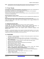
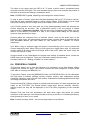
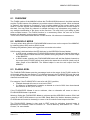
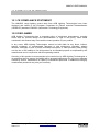
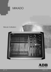
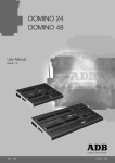
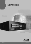
2. GETTING CONNECTED
Main input
Fuse Holder
Power
Switch
Audio
Input
COMMS
PORT
DMX 512
Output
External
Trigger input
2.1 MAINS INPUT
An IEC Mains Input socket is located on the rear panel and a mains power lead is provided.
The MIKADO has an internal power supply that will operate on voltages between 190 volts
and 260 volts AC with a frequency range from 47 to 63 HZ. 110-volt models are available
direct from the factory.
Plug the mains lead into the MAINS INPUT socket and connect it to a source of mains
power. A Power Switch located next to the Mains Input connector allows you to switch the
MIKADO off and on without removing the mains lead. The Mains Input socket is fused with a
M205 sized 500mA fuse.
2.2 DMX512 OUTPUT
The MIKADO transmits a digital signal based on the DMX512/1990 standard.
The output of the MIKADO is DMX512-A "ready". DMX-512A is an upgrade of the standard
that is still under development.
Connect a DMX512 data cable from the 5-pin XLR style connector on the rear panel to the
DMX512 input of your equipment. Set the required DMX512 start address on your
equipment.
At this point, with the mains power and DMX512 connected, the MIKADO is ready to be
operated. Simply switch on the "POWER" switch located near the Mains Input connector.
The MIKADO will commence its start up procedure and will then commence operating in
exactly the same state that it was in when it was last switched off. All the Memories and
Chasers will be as they were.
Hint; if you are starting a new lighting session, ADB recommends that you perform a
"RESET" of the MIKADO. This will ERASE all previously recorded memories and will prevent
you being confused by previous recordings and settings. If you need to keep your memories,
save them to the optional plug-in memory module.
You are now ready to start controlling your lights!
For details on the COMMS PORT, AUDIO INPUT and EXT TRIG Input - refer Section 9 of
this manual- "Utilities".
User Manual - page 8
Issue 1.0
www.adblighting.com
MIKADO USER MANUAL
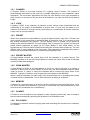
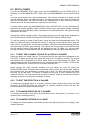
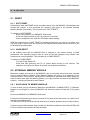
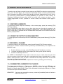
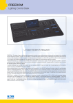
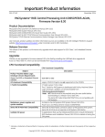
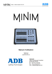
3. FRONT PANEL LAYOUT
The front panel of the MIKADO can de divided up into two areas:
• Preset Faders
• Master section (programming, editing and replaying)
Many of the buttons associated with each fader can have multiple functions. These functions
are described in more detail under the relevant chapters within this manual.
All functions for the MIKADO are laid out in front of the operator in a clear and concise
arrangement. The following chapters will now deal with each function.
Preset A
F /A buttons
Preset B
Submasters
Preset A
Faders
Preset B
F /A buttons
Effect
Menu
Record
Buttons
Preset
Masters
www.adblighting.com
Audio,Speed
And Crossfade
Rotary Faders
Grab
Master
Mode, Page and
Memory Buttons
Flash Level and
Add/Solo button
User Manual - page 9
Issue 1.0
MIKADO USER MANUAL
4. MODES OF OPERATION
4.1 OVERVIEW
The MIKADO has 2 presets.
• The Preset A controls the levels of channels 1 to 12
• The Preset B has different functions depending upon the current "mode" of the
MIKADO as selected by the MODE button. These modes are;
o A / B mode. Preset A controls the levels of channels 1 to 12.
o WIDE mode. The Preset B controls the levels of channels 13 to 24.
o MEMORY mode. The Preset A faders become SUBMASTERS and control the
levels of recorded Memories or Chasers.
You may freely change modes at any time during your operation of the MIKADO and the
current mode is always shown by the "LED" mode indicators beside the MODE button.
Once memories have been recorded, the MEMORY button is used to select how the stored
memories are to be replayed, previewed or edited. The current mode is always shown by the
"LED" indicators beside the MEMORY button.
4.2 A / B MODE
Selecting A / B mode only changes the operation of the preset B. The preset B becomes a
duplicate of the preset A. These two identical banks (A and B) provide duplicate faders for
the 12 channels. The output of each preset is controlled by its own master.
You create a lighting look by fading up your required channels on one of the presets and
fading up the same preset master. By keeping the other master faded down, another look
can be preset on the duplicate set of channel faders without the channels being revealed on
stage. At the appropriate time, the new look is revealed by fading up its master whilst the first
look is faded down with its master. The next look may now be prepared on the preset that
has just been faded down. The fade times of the masters are set by the crossfade rotary
fader.
ADVANTAGE
This mode of operating is most useful in unrehearsed situations where the next "look" needs
to be created "on the fly". The channel faders provide instant "hands on" control of any
channel level.
DISADVANTAGE
Only half of the possible channels can be controlled and any look that needs to be used at a
later time must be manually reproduced with the channel faders.
4.3 WIDE MODE
Selecting WIDE mode only changes the operation of the Preset B. The Preset B becomes a
set of channel faders for the higher numbered channels. Wide mode utilises both the A and B
Preset as a singlewide bank of 24 channels. The Preset A control channels 1 to 12 and the
Preset B faders control channels 13 to 24. There is an individual fader for every channel. The
A Master controls the total output of this single (wide) bank. The B Master is not used in this
mode.
User Manual - page 10
Issue 1.0
www.adblighting.com
MIKADO USER MANUAL
As in Preset mode, you can "balance" the look that you are creating by adjusting the
intensities of the individual channels with their channel faders. You may fade this "look" up
and down with the A Master and of course, you may use the CROSSFADE rotary fader to set
the fade time.
ADVANTAGE
You have access to all of the channels that are available on the MIKADO. This is most useful
when you are recording Memories as you can utilise all channels to create your Memories.
(See "Memory Mode" below).
DISADVANTAGE
You do not have a second Preset on which to create the next look. You can perform
crossfades to another "look" by utilising the Grab Master as a "phantom" bank - see Section
10.4
4.4 Memory MODE
Selecting Memory mode only changes the operation of the Preset B. In Memory mode the
faders of the Preset B become Submasters containing Memories or Chasers.
Memories and Chasers can be recorded or edited whilst operating in any of the three modes
but the Preset A may only be used to replay Memories and Chasers in Memory mode
ADVANTAGE
During rehearsal (in any mode), each lighting look can be created and "recorded" into a
Memory, (with its own fade time if required). During the performance (in Memory mode), the
submaster containing each Memory is simply faded up when required. The MIKADO
remembers (in non-volatile memory) all the channels and their levels together with the fade
times for all of the Memories. You may also use the Submasters (Preset B) to play Chasers
that you have recorded.
4.5 FADE TIMES
When a timed fade is in progress either from the CROSSFADE rotary fader or from memory,
the F/A LED of the fader will flash.
4.5.1 MASTERS
When a A, B or Grab Master is moved, the output level of that master will always progress
towards the current physical position of that master at a rate set by the CROSSFADE rotary
fader.
For example, if a crossfade time of 3 seconds has been set, then to execute a fade in exactly
3 seconds, the master must be moved from bottom to top in less than 3 seconds. If you take
longer than 3 seconds to move the master, then the fade will keep pace with the fader
movement.
A fully manual fade is achieved by setting the crossfade times to 0 seconds. The fade will
then instantly follow the position of the master fader as you move it.
4.5.2 SUBMASTERS
When the MIKADO is in MEMORY mode, the submaster faders are used to submaster
Memories or Chasers that you have recorded in them.
www.adblighting.com
User Manual - page 11
Issue 1.0
MIKADO USER MANUAL
4.5.3 MEMORIES
When a Memory is recorded it looks at the current setting of the CROSSFADE rotary fader.
• If the CROSSFADE rotary fader is set to zero, no times are recorded in the Memory.
When the Memory is played back, the submaster fader is under the live control of the
CROSSFADE rotary fader. It operates in the same manner as the masters described
above.
• If the CROSSFADE rotary fader is set to any value above zero, that exact time is
recorded in the Memory. When the Memory is played back, the recorded time is used
by the submaster fader. The CROSSFADE rotary fader will have no control during
submaster of the Memory.
4.5.4 CHASERS
When a Chaser is recorded it looks at the current setting of the CROSSFADE rotary fader
and the SPEED rotary fader.
• If the CROSSFADE rotary fader is set to zero, no crossfade times are recorded in the
Chaser. When the Chaser is played back, the crossfade between steps is under the
live control of the CROSSFADE rotary fader.
• If the CROSSFADE rotary fader is set to any value above zero, that exact time is
recorded in the Chaser. When the Chaser is played back, the recorded time is used
to crossfade between steps. The CROSSFADE rotary fader will have no control
during the submaster of the Chaser.
• If the SPEED rotary fader is set to zero, no SPEED is recorded in the Chaser. When
the Chaser is played back, the SPEED is under the live control of the SPEED rotary
fader.
• If the SPEED rotary fader is set to any value above zero, that exact speed is recorded
in the Chaser. When the Chaser is played back, the recorded SPEED is used. The
SPEED rotary fader will have no control during the submaster of the Chaser.
If a submaster contains a Chaser, then the submaster fader always performs manual fades
of the overall Chaser intensity level. The position of the fader instantaneously sets this level
4.5.5 CHANNELS
All individual channel faders perform manual fades. The position of the fader instantaneously
sets its level.
4.6 MEMORY RUN
The MEMORY RUN mode is used to submaster the previously recorded Memories and
Chasers. The MIKADO must also be in MEMORY mode, so the Submaster faders (Preset A)
are acting as Submasters for the stored memories. For memory-based shows, this
configuration ("memory" and "run") is the common submaster mode.
4.7 MEMORY PREVIEW
MEMORY PREVIEW mode is used to preview previously stored memories without revealing
them on the output. The content of a previewed Memory or Chaser is shown on the F/A
channel buttons including any associated times and speeds. Normal submaster of Memories
or Chasers is still maintained whilst in PREVIEW mode.
To preview a memory, press [MEMORY] until the preview LED lights then press [F/A]
(memory to preview). To see which memory locations have been used, tap [PAGE] to select
the required page then press and hold [PAGE].
User Manual - page 12
Issue 1.0
www.adblighting.com
MIKADO USER MANUAL
The submaster flash/assign buttons containing Memories will light, submasters containing
Chasers flash quickly and empty submasters are not lit.
When you press any RECORD button or change MEMORY to "preview" or "edit" mode, all
submaster flash/assign buttons flash twice (to show that they are possible memory
locations), then they show their contents as above. If you change pages whilst in "record",
"preview" or "edit" modes, the contents of each page is shown.
4.8 MEMORY EDIT
The MEMORY EDIT mode is very similar to the MEMORY PREVIEW mode, except that the
contents of the memory can now be altered. EDIT mode allows you to adjust channel levels
and fade times in Memories (see Section 5.5) and to adjust all Chaser parameters including
the adding or deleting of steps (see section 6.5).
4.9 MODE/PAGE FREEZE
A MODE/PAGE FREEZE feature prevents the contents of a live fader from being changed if
its level is above 5% when a MODE (A/B /wide/memory) or PAGE (one/two/three) is
changed.
The current contents of any "live" fader is held until such time as that fader is faded down
below 5% when it will be automatically updated with its pending assignment for the new
mode or page. This prevents Memories, Chasers or channels "crashing in" on stage if their
fader is contributing to the output when a different mode or page is selected.
Whenever there is a pending Memory, Chaser or channel change due to a MODE change or
PAGE change, the relevant MODE "LED" indicator (A/B , wide or memory) or the relevant
PAGE "LED" indicator (one/two/three) will flash. This acts as a warning to you that the
flashing mode and/or page is not currently selected but it is contributing to the current output.
Therefore, the contents of a submaster may change (to the current mode or page) after it is
faded down.
4.10 FADER MATCHING/CAPTURE
As you change Memory Modes on the MIKADO (run/preview/edit) the CROSSFADE and
SPEED rotary faders can be changed without affecting other modes. For example, if you are
in Run Mode and the speed is set to 999, then you edit another Chaser and rotate the speed
to zero without changing the speed of the running Chaser. Therefore when you return to Run
Mode the fader is no longer active, as it is not set to the original 999 level. 'Matching' is used
to get control back without any sudden jump in level.
If a rotary fader is not active (E.g. Requires level matching to activate), then the LED
indicator will not be lit. Rotate the fader clockwise/counter clockwise until you match the
level, the LED will light or start flashing to indicate that the fader has captured the level and is
now in control.
www.adblighting.com
User Manual - page 13
Issue 1.0
MIKADO USER MANUAL
5. MEMORIES
5.1 OVERVIEW
A MEMORY is a recorded snapshot of the Mikado’s output, together with fade time settings,
that is stored in non-volatile memory. Memories are recorded by Page and Memory number.
Memories may be randomly recorded into any Page and Memory number at any time,
irrespective of the current "MODE" (Preset, Wide or Memory) of submasters.
Memories may be created "blind" (not appearing on the output) using the "EDIT" function.
Memories can be replayed on the submasters (in Memory mode) or as steps in Chasers.
When a page is changed or when the preset B is selected to "MEMORY" mode, the contents
of the indicated page (Memories and Chasers) are loaded into the submasters.
Memory submaster fade times may be controlled live from the CROSSFADE rotary fader or
may be recorded in memory as part of the Memory. Individual fade time may be recorded for
every Memory.
5.2 RECORDING A MEMORY
To record a Memory, create the look on the faders with the Preset Master up, then press
[record memory] [PAGE] (optional) (select page 1,2 or 3) [F/A] (Memory number).
Or to record a Memory in the Grab Master, press [record memory] [F/A] (GRAB).
When the [record memory] button is pressed, its LED will flash to show that it is active. All
submasters will flash twice to indicate possible memory location choices, then submasters
already containing Memories in that page will light. (submasters containing Chasers flash
quickly and empty submasters are not lit.) This acts as a warning to you of existing Memory
(and Chaser) numbers and unused numbers in each page.
Note: Recording over an existing Memory or Chaser number will erase the previous
contents.
A Memory with NO channel levels on the output will not be recorded. (See BLIND
RECORDING below).
5.2.1 RECORDING FADE TIMES
If a Memory is recorded with the CROSSFADE rotary fader set to zero, no crossfade setting
will be stored with the Memory. When the Memory is played back the CROSSFADE rotary
fader can be used to vary the fade time of the submaster fader containing the Memory.
If a Memory is recorded with the CROSSFADE rotary fader set above zero, the crossfade
setting will be stored with the Memory. To add a crossfade to the recorded Memory, adjust
the [crossfade] rotary fader to set the required setting prior to ending the recording of the
Memory. When the Memory is played back the submaster fader containing the Memory will
use the setting when the Memory was recorded. The CROSSFADE rotary fader cannot be
used to vary the fade time.
The crossfade can be varied after recording by editing the Memory.
User Manual - page 14
Issue 1.0
www.adblighting.com
MIKADO USER MANUAL
5.2.2 ABANDONING A RECORDING
When you have created your look, pressed REC MEMORY, set the fade time and/or
selected a page, you still have one last chance to abandon the Memory you are recording
without destroying any previously stored memories.
To abandon the RECORD MEMORY function, press [rec memory] a second time, prior to
pressing a [F/ A] (memory number) button.
5.2.3 BLIND RECORDING
Memories may be created blind (not appearing on the output) by editing an existing Memory
that is no longer required. See Section 8.5 - "Edit a Memory" below for details.
Hint; If you are required to record several "blind" Memories during a performance, make
some preparations by recording the required Memory numbers prior to the show. The
MIKADO will not record a Memory if there are no channels on the output so set only 1
channel ON at a low level and record it in the memory numbers. When you know the channel
numbers that you will need in the blind memory, edit that Memory and set the single channel
to 0 and turn on the required channels.
5.3 SUBMASTER A MEMORY
Memories are normally played back in MEMORY RUN mode.
Press and hold [MEMORY] until RUN LED is lit.
Memories may be replayed on the submasters (in Memory mode) or on the Grab Master (if
previously recorded in the Grab Master).
To submaster a Memory recorded on the Grab Master, simply fade it up.
To submaster a Memory on a submaster, press [MODE] until the Memory LED is lit.
Press [PAGE] until required page number is lit. Fade up Preset B master and then fade up
submaster to reveal the Memory.
If the Memory to be replayed has no stored fade times, then fade times can be controlled live
using the CROSSFADE rotary fader. The fader is only active when the LED is lit. To make it
active rotate it clockwise/counter clockwise until the LED lights. This now indicates that you
have now matched the position of the fader to the last active setting in submaster mode.
Note: CROSSFADE is global, adjusting it will change ALL active Memories.
If the Memory to be replayed has a stored fade time the CROSSFADE rotary fader has no
effect. Memories stored on the Grab Master are played back exactly as detailed above,
except the PAGE button has no influence. Times are controlled exactly the same way.
5.4 PREVIEW A MEMORY
This function allows you to view the contents of a submaster or the Grab Master without
revealing the Memory on stage. The Preview function will work irrespective of which mode
(A/B , wide or memory) the MIKADO is in.
To preview a Memory, press [MEMORY] button until PREVIEW LED is lit. All submasters will
flash twice to indicate possible memory location choices, then submasters already containing
Memories in that page will light. (submasters containing Chasers flash quickly and empty
submasters are not lit.) Press and hold [F/A] (Memory number to preview) and the channel
levels of the Memory will then be displayed on the F/A LEDs.
www.adblighting.com
User Manual - page 15
Issue 1.0
MIKADO USER MANUAL
Release [F/A] and then the submasters will flash twice again and reveal the stored
memories. At this point you can choose another memory to preview.
If a Memory has a stored fade time, by holding the [F/A] button, you will see the channel
levels fade in on the LEDs. Releasing the [F/A] button will instantly snap the Memory off.
Note: Preview is always "blind" - the current stage output is not affected.
5.5 EDIT A MEMORY
To enter the MEMORY EDIT mode, press and hold [MEMORY] until the EDIT LED is lit.
Similarly, to exit the MEMORY EDIT mode, press and hold [MEMORY] until the RUN LED is
lit. You may edit a Memory live or blind (faded down). If the Memory is faded up on stage you
will see the changes. When you edit the Memory its channel levels are shown on F/A LED
indicators.
To edit a Memory, press and hold [MEMORY] button until EDIT LED is lit. All submasters will
flash twice to indicate possible memory location choices, then submasters already containing
Memories in that page will light. (Submasters containing Chasers flash quickly and empty
submasters are not lit.). Press [F/A] (Memory number). The channel levels of the Memory will
be displayed on the F/A LEDs and the FUNCTION button LED will flash.
5.5.1 ADJUSTING CHANNEL LEVELS
Press and hold [F/ A] (channel number) and the percentage level of that channel in the
Memory will be displayed on the Edit Value Scale on the submasters F/A buttons LEDs. The
display shows the level of channel output in 5% increments using the 10 LEDs - A LED at full
intensity indicates 10% and a LED at 50% intensity indicates 5%.
Whilst holding the [F/ A] (channel number) you can adjust the level by fading the
[FLASH/LEVEL] fader. The Edit Value Scale will follow the level set by this fader. The fader
does not become active until the level of the fader matches the recorded level, thus
preventing a sudden jump in level.
To remove a channel set its level to zero. Release the [F/ A] (channel number). The new
level will be recorded. If desired, select a new channel to adjust, including channels not
previously recorded in the step.
5.5.2 ADJUSTING FADE TIMES
To adjust a stored time, rotate the [crossfade] rotary fader clockwise/counter clockwise until
the LED lights (this indicates the previously recorded level) then set the time using the scale
printed around the rotary fader.
If the crossfade time is set to zero, no crossfade setting will be stored with the Memory.
When the Memory is played back the CROSSFADE rotary fader can be used live to vary its
fade time.
If the crossfade time is set above zero, the crossfade setting will be stored with the Memory.
When the Memory is played back it will fade in and out at the recorded time. The
CROSSFADE rotary fader cannot be used to vary its fade time during submaster.
To exit the EDIT mode, press and hold the [MEMORY] button until the RUN LED is lit.
User Manual - page 16
Issue 1.0
www.adblighting.com
MIKADO USER MANUAL
5.6 DELETE A MEMORY
To delete a Memory, record a blackout (no output) Memory over the existing memory. This
will empty the submaster memory location.
To create a blackout, fade all three Masters to the fully down position and ensure that they
have completed their fade by observing that their F/A LEDs are not flashing.
Press [record memory] [F/A] (memory number to be deleted).
www.adblighting.com
User Manual - page 17
Issue 1.0
MIKADO USER MANUAL
6. CHASERS
6.1 OVERVIEW
A Chaser is a recorded list of steps that are to be replayed in order, stepping continuously
from one-step to the next and automatically repeating the list when it has reached the end.
Each step in a Chaser consists of a Memory or a snapshot of the output (which is taken
when that step is added to the Chaser). Up to 24 steps may be recorded for each Chaser
and up to 37 separate Chasers may be recorded into the memory. 13 simultaneous Chasers
can be run at any one time.
Chasers are recorded by page and Chaser number. Page numbers are selected with the
PAGE button and Chaser numbers are selected with the red F/A buttons. Chasers may be
randomly recorded into any page and Chaser number, however Memories and Chasers
share the same memory locations within each page, so recording a Chaser into the F/A of an
existing Memory will REPLACE the Memory with the Chaser (and visa-versa). Chasers may
also be recorded directly into the Grab Master.
Chaser rate and crossfade times can be recorded in memory as part of each Chaser.
Chasers may be run in any of the following modes;
• FORWARD
• REVERSE
• BOUNCE (Auto reverse at each end)
• SINGLE SHOT (Run once and stop) (in either direction)
• RANDOM (computer generated random sequence)
• MANUALLY STEPPED FORWARD (Ideal for running sequences with an external
"GO" button)
• MANUALLY STEPPED REVERSE
The Chaser SPEED (rate) can be manually controlled or recorded into memory in BPM
(Beats per Minute).
Chaser stepping may be synchronised to the beat of an Audio Input signal.
Chaser stepping may be under the control of an external switch.
Traditionally, Chasers will snap (instantly switch) from step to step but you may also elect to
crossfade from step to step. The crossfade time can be manually controlled or recorded into
memory.
A Chaser may be edited. The contents of any step may be changed, the speed varied and
steps may be added or deleted.
6.2 RECORDING A CHASER
To record a chaser, press [record chaser] [PAGE] (optional) (select page one, two or three)
[F/ A] (chaser number) (any of the Red Bank Flash/Assign buttons).
Or to record a Chaser in the Grab Master, press [record chaser] [F/ A] (GRAB).
Each step of a Chaser can consist of a previously recorded Memory or a snapshot of the
current output. Up to 24 steps can be recorded in each Chaser.
User Manual - page 18
Issue 1.0
www.adblighting.com
MIKADO USER MANUAL
To record a Memory as a step, select the required page by tapping [PAGE] (optional) then
tap [F/A] (Memory number). You cannot record a Chaser as a step in a Chaser.
To record a snapshot of the output as a step, create the desired look on the output, then
press [record memory].
Continue to record steps as above.
When all steps have been recorded, press [record chaser] to end.
6.2.1 RECORDING THE SPEED (RATE)
If a Chaser is recorded with the SPEED rotary fader set to zero, no speed will be stored with
the Chaser. When the Chaser is played back the SPEED rotary fader can be used to vary
the speed manually.
If a Chaser is recorded with the SPEED rotary fader set above zero, the speed setting will be
stored with the Chaser.
To add a speed to the recorded Chaser, adjust the [speed] rotary fader clockwise/counter
clockwise until the LED lights or starts flashing (this indicates the previous submaster speed)
then set the rate using the flashing LED to gauge the speed.
The speed can be varied after recording by editing the Chaser (see below).
6.2.2 RECORDING THE CROSSFADE TIME
If a Chaser is recorded with the CROSSFADE rotary fader set to zero, no crossfade setting
will be stored with the Chaser. When the Chaser is played back the CROSSFADE rotary
fader can be used to vary the crossfade between steps manually.
If a Chaser is recorded with the CROSSFADE rotary fader set above zero, the crossfade
setting will be stored with the Chaser.
To add a crossfade to the recorded Chaser, adjust the [crossfade] rotary fader
clockwise/counter clockwise until the LED lights (this indicates the previous submaster
crossfade setting) then adjust the rate using scale printed around the rotary fader.
The crossfade can be varied after recording by editing the Chaser.
www.adblighting.com
User Manual - page 19
Issue 1.0
MIKADO USER MANUAL
6.2.3 RECORDING DIRECTION MODE AND TRIGGER EFFECTS
When a Chaser is recorded, it will be by default a forward running continuous Chaser. You
can set the direction (forward or reverse) or the pattern (continuous, single shot, bounce,
random) or the triggering (speed, bass or external) and save these settings as part of the
Chaser. At any time after selecting the Chaser number and prior to ending the recording of a
Chaser, press and hold [function]. The F/A buttons of the Yellow Bank flash twice to show
you the available options and then the current selections continue to flash
Direction Button Flashing
>
<
Effect
Forward direction
Reverse direction
Pattern Button Flashing
None
Single
Bounce
Random
Effect
Continuous
Single shot in selected direction
Bounce end to end
Random Patterns
Trigger Button Flashing
None
Single
Bounce
Effect
Stepping under speed setting
Bass Audio stepping
External switch stepping
Whilst holding [function], tap [F/A] (the required effect). The Pattern and Trigger buttons are
a toggle function, where only one (or no) button can be selected at a time
The Effects can be varied after recording by editing the Chaser.
6.3 SUBMASTER A CHASER
Chasers are normally played back in MEMORY RUN mode. Press [MEMORY] until RUN
LED is lit. Chasers may be replayed on the submasters (in Memory mode) or on the Grab
Master (if previously recorded in the Grab Master).
To submaster a Chaser recorded on the Grab Master, simply fade it up.
To submaster a Chaser on a submaster, press [MODE] until the MEMORY LED is lit.
Press [PAGE] until required page number is lit. Fade up Red Master and then fade up
submaster to reveal the Chaser.
6.3.1 CONTROLLING A CHASER
If the Chaser to be replayed has no stored speed (rate), then the speed can be controlled live
using the SPEED rotary fader. The fader is only active when the LED is lit or flashing. To
make it active rotate it clockwise/counter clockwise until the LED lights or flashes. This now
indicates that you have now matched the position of the fader to the last active setting in
submaster mode.
Note: SPEED is global, adjusting it will change ALL active Chasers.
If the Chaser to be replayed has no stored crossfade, then fade rate can be controlled live
using the CROSSFADE rotary fader.
User Manual - page 20
Issue 1.0
www.adblighting.com
MIKADO USER MANUAL
The fader is only active when the LED is lit. To make it active rotate it clockwise/counter
clockwise until the LED lights. This now indicates that you have now matched the position of
the fader to the last active setting in submaster mode.
Note: CROSSFADE is global, adjusting it will change ALL active Chasers.
To stop or start a Chaser, press and hold [start/stop/step] then tap [F/ A] (Chaser number).
Each tap will start a stopped Chaser or stop a running Chaser. If the Chaser is set to single
shot mode, each tap will run a single shot of the Chaser in the current direction.
If the Chaser speed is zero then each tap of the [start/stop/step] button will advance the
Chaser sequence by one-step. This is particularly useful if you are playing a Chaser
sequence like a Theatrical crossfade. With the use of the [crossfade] rotary fader, you can
fade in a new Memory recorded as a step in the Chaser whilst fading out the Memory
(previous step) presently on stage.
Chasers which are controlled from an external source, such as the Audio Input or the
External Trigger Input, will automatically advance when a trigger signal is received and the
Red Submaster Master has been faded up. See Section 12.0 - "Utilities" for further
information.
Hint: When using an external trigger the speed is automatically set to zero to prevent the
Chaser stepping by itself. When using an audio signal as a trigger (bass step), try setting the
Chaser speed to be slower than the average beat of the music. When the music stops, the
Chaser will continue to step.
Chasers stored on the Grab Master are played back exactly as detailed above, except the
PAGE button has no influence. Times are controlled in exactly the same way.
See also Section 9.5 - "Editing a Chaser" for control options.
6.4 PREVIEW A CHASER
This function allows you to view the contents of a submaster or the Grab Master without
revealing the Chaser on stage. The Preview function will work irrespective of which mode
(A/B, wide or memory) the MIKADO is in.
To preview a Chaser, press the [MEMORY] button until PREVIEW LED is lit. All submasters
will flash twice to indicate possible memory location choices, then submasters already
containing Chasers in that page will flash quickly. Submasters containing Memories will light
and empty submasters are not lit.
Press and hold [F/A] (Chaser number to preview) and the Chaser, as it was programmed, will
replay on the F/A LEDs. The Chaser pattern (single shot, bounce, random), direction,
channel output per step will be displayed on the F/A LEDs progressing at the recorded
speed.
Release [F/A] and then the submasters will flash twice again and reveal the stored
memories. At this point you can choose another memory to preview, or if finished previewing,
press [memory] to return to run mode
Note: Preview is always "blind" - the current stage output is not affected.
www.adblighting.com
User Manual - page 21
Issue 1.0
MIKADO USER MANUAL
6.5 EDIT A CHASE
To enter the MEMORY EDIT mode, press and hold [MEMORY] until the EDIT LED is lit.
Similarly, to exit the MEMORY EDIT mode, press and hold [MEMORY] until the RUN LED is
lit.
You may edit a Chaser live or blind (faded down). If the Chaser is faded up on stage you will
see the changes. When you edit the Chaser, its channel levels for each step are shown on
the F/A LED indicators. The LEDs will fade in the crossfade time (if any). Their final intensity
reflects the levels of those channels in each step of the Chaser.
To edit a Chaser, press and hold [MEMORY] button until EDIT LED is lit. All submasters will
flash twice to indicate possible memory location choices, then submasters already containing
Chasers in that page will flash quickly. Submasters containing Memories will light and empty
submasters are not lit.
Press [F/A] (Chaser number to edit). The channel levels of the first step will be displayed on
the F/A LEDs and the FUNCTION and START/STOP/STEP buttons LED will flash.
To view the number of steps in the Chaser, press and hold the [start/stop/step] button. The
fader F/A LEDs will light to indicate the number of steps (up to 24) and the current step will
flash quickly. To change the current step to another, press and hold [start/stop/step] then tap
the required [F/A] button (step number). The Chaser will now advance to the selected step
and the channel levels of that step will be displayed on the F/A LEDs. You can also step
through the chaser in programmed order by repeatedly pressing the [start/stop/step] button.
6.5.1 TO EDIT THE CHANNEL LEVELS OF A STEP IN A CHASER
Select the step to be edited (above). The channel levels in the step will be displayed on the
F/A LEDs. To adjust a channel level, press and hold the [F/ A] (channel number). The level of
that channel will be displayed on the Edit Value Scale on the Submasters F/A LEDs. The
display shows the level of channel output in 5% increments using the 10 LEDs - A LED at full
intensity indicates 10% and a LED at 112 intensity indicates 5%.
Whilst holding the [F/A] (channel number) you can adjust the level by fading the
[FLASH/LEVEL] fader. The fader does not become active until the level of the fader matches
the recorded level, thus preventing a sudden jump in level. The Edit Value Scale will follow
the level set by this fader. To remove a channel set its level to zero. Release the [F/A]
(channel number). The new level will be recorded. If desired, select a new channel to adjust,
including channels not previously recorded in the step.
6.5.2 TO EDIT THE EFFECTS IN A CHASER
To change the recorded effect on a Chaser, edit the Chaser (above) then press and hold
[function]. All EFFECTS LEDs will flash twice to indicate possible choices and then the
current programmed effects will flash quickly.
6.5.3 TO CHANGE DIRECTION OF A CHASER
To change the direction, hold down the [function] button, then press [<] (reverse) or [>]
(forward), then release [function].
6.5.4 TO CHANGE PATTERN OF A CHASE
To change the Chaser pattern, hold down [function] tap [random], [bounce] or [single], then
release [function].
User Manual - page 22
Issue 1.0
www.adblighting.com
MIKADO USER MANUAL
6.5.5 TO ACTIVATE EXTERNAL TRIGGER TO RUN A CHASE
To link the External Trigger Input to activate the Chase, hold down [function] tap [extern],
then release [function].
6.5.6 TO ACTIVATE AUDIO INPUT TO RUN A CHASE
To link the Audio Input to activate the Chase, hold down [function] tap [bass], then release
[function].
6.5.7 TO ADD A STEP IN A CHASE
Edit the Chase (above) then press and hold the [start/stop/step] button and tap the [F/ A]
button (step number) to advance the Chase to the step where the new step is to be added.
The new step will be inserted prior to the selected step. In order to add a step onto the end of
a chaser select the 181 step and the new step will be inserted onto the end of the chaser.
Whilst holding down the [function] button, press [add], then release [function]
The RECORD SCENE LED will flash to indicate that you can record a snapshot of the
output. To add a previously recorded Scene as a step, press [PAGE] (optional to select the
page containing the Scene) then press [F/A] (Scene number).
To add a snapshot as a step, create the look on the output and then press [record scene].
HINT: when recording a snapshot of the output as a step, remember to keep the Chase
faded down so that it is not included in the new step.
The new step has now been added.
6.5.8 TO DELETE A STEP IN A CHASER
Edit the Chaser (above) then press and hold the [start/stop/step] button and tap the [F/A]
button (step number) to advance the Chaser to the step that is to be deleted.
Whilst holding down the [function] button, press [delete], then release [function].
The step number selected above will now be deleted. If you delete all the steps of a chaser
then the MIKADO keeps a blank (blackout) step as the first step, to enable the editing and
inserting of new steps.
6.5.9 TO CHANGE THE SPEED OF A CHASER
The recorded speed will be displayed by the flash rate of the SPEED LED indicator. If the
speed has been recorded at zero level, then the LED will be permanently lit. To adjust the
recorded speed, rotate the [speed] rotary fader clockwise/counter clockwise until the LED
illuminates. This indicates that you have matched the recorded value and the rotary fader is
now controlling the speed.
6.5.10 TO CHANGE THE CROSSFADE TIME OF A CHASER
To view the recorded crossfade level of a Chaser, rotate the [crossfade] rotary fader
clockwise/counter clockwise until the LED is lit. This will indicate the recorded level. The level
is now under the control of the rotary fader and any adjustments will now be saved in the
Chaser memory.
6.6 DELETE A CHASER
To delete a Chaser,
press [record chaser] [F/A] (Chaser number to be deleted) [record chaser].
www.adblighting.com
User Manual - page 23
Issue 1.0
MIKADO USER MANUAL
7. GRAB MASTER
7.1 Overview
The Grab Master is a multi function master. It can be used as either;
• A Memory master.
• A Chaser master.
• A (phantom) Preset master.
You change its function by what you record in it.
7.2 GRAB MASTER AS A MEMORY MASTER
The Grab Master can be used as a memory location for a Memory. In effect, it is creating
another Memory that can be concurrently replayed along with the other 12 submasters.
To record the output of the MIKADO in the Grab Master, press [record memory] [F/A]
(GRAB).
The contents of the Grab Master (including its fade time), may be edited in exactly the same
manner as a Memory. See Section 8.5 - "Editing a Memory".
7.3 GRAB MASTER AS A CHASER MASTER
This is the same procedure as recording a Chaser on a submaster except that the Grab
Master is selected as the Chaser number. The Chaser in the Grab Master may be controlled
and edited in exactly the same manner as a Chaser in a submaster.
To record a Chaser in the Grab Master, press [record chaser] [F/A] (GRAB).
Each step of a Chaser can consist of a previously recorded Memory or a snapshot of the
current output. Up to 24 steps can be recorded in the Chaser.
To record a Memory as a step make sure that the [MODE] button is set to Memory, press
[PAGE] (optional) then tap [F/A] (Memory number). You cannot record a Chaser as a step in
a Chaser.
To record a snapshot of the output as a step, create the desired look on the output, then
press [record memory].
Continue to record steps as above.
When all steps have been recorded, press [record chaser] to end.
7.4 GRAB MASTER AS A PHANTOM PRESET MASTER
When you perform a "Grab" and then fade up the Grab Master, it allows the Preset Masters
(and hence the channel faders and/or submasters) currently producing the output to be faded
down whilst the Grab Master maintains the output. This allows the next look to be preset
"blind" on either of the preset banks. This is most useful in WIDE and MEMORY modes as
the Grab Master effectively provides a ("Phantom") submaster page.
User Manual - page 24
Issue 1.0
www.adblighting.com
MIKADO USER MANUAL
In a typical operation, the current look is created on any of the channel faders or submasters.
To enable the next look to be created, take a "Grab" of the output [record memory], [F/ A]
(GRAB), fade up the Grab Master to full and then fade down the Preset Masters. The look on
stage is maintained by the Grab Master. Preset the next look using any of the channel faders
or submasters. To crossfade to the next look, simply fade up the Preset Masters and fade
down the Grab Master. In order to create the next look, "Grab" the current look in the Grab
Master, fade it up to full and then fade down the Preset Masters. As before, create the next
look "blind" on the channel faders or submasters.
You may continue to "Preset" and "Grab" for every new look that you require.
www.adblighting.com
User Manual - page 25
Issue 1.0
MIKADO USER MANUAL
8. FLASH
8.1 OVERVIEW
The FLASH section of the MIKADO utilises the FLASH/ASSIGN buttons in the fader sections
and the FLASH buttons of the Master's to provide extensive flashing control. When a channel
is "flashed" (also known as "bumping") it can be either added to the current output of the
desk or it can be "soloed" (also known as swap or kill) where it replaces the current output of
the desk. You may Flash any channel or multiple channels, any submasters, any master, or
any multiple combination of the above at the one time. The only limit is your ability to hold
down multiple buttons. The FLASH function is a momentary action. As soon as all Flash
buttons are released, normal output is restored.
There are no times associated with the FLASH function. All actions are instantaneous.
8.2 ADD/SOLO MODE
You may select what effect the FLASH/ASSIGN buttons have on the output of the MIKADO,
by selecting either ADD mode or SOLO mode.
Pressing the [add/solo] button will toggle from one mode to the other.
SOLO mode is indicated when the LED indicator in the ADD/SOLO button flashes.
• In ADD mode, pressing any FLASH/ASSIGN button will add the flashed channels to
the output (at the FLASH control level) without having any effect on the current output
of the MIKADO.
• In SOLO mode, pressing any FLASH/ASSIGN button will add the flashed channels to
the output (at the FLASH control level) and at the same time it will KILL (black out) all
other output of the MIKADO. The flashed object is now the solo output from the
MIKADO.
8.3 FLASH/LEVEL
The FLASH/LEVEL Master sets the percentage level at the output of the FLASH section for
all channels when they are flashed. For individual channels the FLASH/LEVEL sets the level
of any flashed channels. For the contents of any Submaster it will be the percentage of the
channels recorded level.
For example, if the FLASH/LEVEL is set to its mid (50%) position;
• Flashed channels will come on at a level of 50%.
• If a Memory is flashed and it contains a channel at a level of 80% then that channel
will come on at 40% (50% of 80%).
If the FLASH/LEVEL Master is set to minimum, then no channels will come on when a
FLASH/ASSIGN button is pressed.
Warning: Setting the FLASH/LEVEL Master to minimum and the ADD/SOLO mode to SOLO will
cause all of the FLASH buttons to act as DBO (Dead Black Out) buttons because pressing a
FLASH button will cause its channel(s) to come on at 0% and all normal output to be killed.
The FLASH/LEVEL Master is also used in EDIT mode for adjusting channel levels in
Memories and Chasers. Refer to Section 5.5 - "Edit a Memory" and Section 6.5 - "Edit a
Chaser", for more details.
User Manual - page 26
Issue 1.0
www.adblighting.com
MIKADO USER MANUAL
9. UTILITIES
9.1 RESET
9.1.1 SOFT RESET
Performing a reset will ERASE all the recorded memory from the MIKADO. All Memories and
Chases are erased. If your memories are required, save them to the optional External
Memory Module (see below). This is known as a "SOFT RESET".
To perform a SOFT RESET,
Ensure the MIKADO is in MEMORY RUN mode.
Press and hold [function] and [F/ A] (reset) for 5 seconds.
At the completion of the reset the F/A button stops flashing.
ADB also suggests that a SOFT RESET is performed each time you start a new show, as it
is a quick way to ensure that ALL memories are deleted and ensures that the console is set
to the default operating state.
9.1.2 HARD RESET
In the unlikely event that the MIKADO fails to respond to your button strokes or fader
movements, the operating system may be reset so that the software may initialise and
recommence normal operation. This is known as a "HARD RESET".
To perform a HARD RESET,
Turn the Power Switch off.
Press and hold [function] and [F/ A] (reset) whilst turning on the console. This
operation will require two hands to prevent any accidental activation.
9.2 EXTERNAL MEMORY MODULE
Memories created and stored in the MIKADO, can be externally saved and then reloaded
from an external Memory Module. Each Memory Module can hold up to a maximum of four
complete shows. This module is optional and is available for purchase from ADB. When you
save or load a show from the Memory Module, you copy the entire contents of the MIKADO’s
memory - including all Memories and Chases.
9.2.1 SAVE SHOW TO MEMORY MODULE
To save a show, plug-in the Memory Module to the MIKADO’s "COMMS PORT". If a Memory
Module is not plugged in, then the MIKADO will detect this and not flash the [F/ A] (save)
LED.
Ensure the MIKADO is in MEMORY RUN mode
Press and hold [function] then press and hold [F/ A] (save) at the same time, for a period of 5
seconds, then release both.
The first four LEDs on the Preset B will flash twice to indicate possible show number choices.
If previous shows have already been loaded into the Memory Module, the Preset B LEDs will
be lit to indicate show numbers already allocated.
www.adblighting.com
User Manual - page 27
Issue 1.0
MIKADO USER MANUAL
It is possible to write over an existing show at this stage, so it is recommended to use a free
location if you are unsure what is presently loaded.
Press [F/A] (show number) to save the show.
Saving a show takes a few moments. A progress meter is displayed on the Edit Value Scale
LEDs. During this time normal operation of the MIKADO is not possible
9.2.2 LOAD SHOW FROM MEMORY MODULE
When you load a show from the Memory Module, you replace the entire contents of the
MIKADO's memory with the show data on the Memory Module. This includes all Memories
and Chases.
To load a show, plug-in the Memory Module to the "COMMS PORT". If a Memory Module is
not plugged in or if the Memory Module is empty, then the MIKADO will detect this and not
flash the [F/A] (load) LED.
Ensure the MIKADO is in MEMORY RUN mode.
Press and hold [function] then press and hold [F/ A] (load) at the same time, for a period of 5
seconds, then release both.
The MIKADO will interrogate the Memory Module to see what shows exist. The show
numbers saved will be flashed on the corresponding Preset B LEDs.
Press [F/ A] (show number) to load the selected show.
Loading a show takes a few moments. A progress meter is displayed on the Edit Value Scale
LEDs. During this time normal operation of the MIKADO is not possible.
WARNING: Once a load from the Memory Module is initiated, the current contents of
the MIKADO's memory will be erased and cannot be recovered.
Note: If a save or load error occurs, the MIKADO will stop all data transfer, flash all LED's
on the front panel for 5 seconds and then resume to its state prior to the save or load
function. Try the save or load again and if the same problem persists, then ADB
recommends changing the Memory Module with another. If data errors still occur,
then contact ADB.
9.3 AUDIO INPUT
The MIKADO is fitted with a RCA (phono) type socket to accept an audio signal. The audio
signal should have a nominal level of 1 volt RMS (line level). The audio signal can be used to
trigger the stepping of a Chaser (or chasers) by selecting the BASS STEP function.
An AUDIO LEVEL rotary fader is used to adjust the sensitivity of the audio signal input. If the
bass signal from the music is weak, then the AUDIO LEVEL will need to be increased to
activate the Chaser stepping.
To activate the Audio Input to a Chaser:
Press and hold [MEMORY] until the EDIT LED is lit.
Select the Chaser to edit, press [F/ A] (Chaser number). hold [function] tap [F/ A] (bass).
Tapping [F/A] (bass) will toggle the bass on or off.
Exit EDIT by pressing and holding [MEMORY] button until RUN LED is lit.
User Manual - page 28
Issue 1.0
www.adblighting.com
MIKADO USER MANUAL
The Chaser is now controlled by the Audio Input. Fade up the submasters containing the
Chaser and also the submaster Master (preset B). Adjust the [audio level] rotary fader until
the Chaser begins to step. If the CROSSFADE rotary fader is set at 0 (zero), each Chaser
step will snap (instantly switch) from step to step. If you require a "smoother" fade from step
to step, then adjust the crossfade rate by rotating the [crossfade] rotary fader.
To adjust the audio level turn the Audio Level control until the LED is flashing in sync with the
music source. If the LED is continuously lit then the audio level is too loud, turn down the
rotary fader until the LED flashes regularly.
9.4 EXTERNAL TRIGGER INPUT
The rear panel has a ¼" mono jack (EXT TRIG) for connecting contact closure type devices
(such as a footswitch) to remotely advance the steps of a Chaser.
Note: The switching device must NOT output any voltage otherwise the MIKADO console
will be damaged.
To activate the External Trigger Input to a Chaser:
Press and hold [MEMORY] button until EDIT LED is lit.
Select the Chaser to edit, press [F/ A] (Chaser number). Hold [function] tap [F/ A] (extern).
Tapping [F/A] (extern) will toggle the external on or off.
Exit EDIT by pressing and hold [MEMORY] button until RUN LED is lit.
The Chaser is now controlled by the External Trigger Input. Fade up the submaster
containing the Chaser and also the submaster Master. If the CROSSFADE rotary fader is set
at 0 (zero), each Chaser step will snap (instantly switch) from step to step. If you require a
"smoother" fade from step to step, then adjust the crossfade rate by rotating the [crossfade]
rotary fader.
Note: While a Chaser with an Audio Input or External Trigger Input is running, it is still
possible to concurrently run other stored memories and Chasers on the submasters
and Grab Master.
www.adblighting.com
User Manual - page 29
Issue 1.0
MIKADO USER MANUAL
10. COMPLIANCE STATEMENTS
10.1 CE COMPLIANCE STATEMENT
The MIKADO range lighting control desk from ADB Lighting Technologies have been
designed and tested to the European Committee for Electro technical Standardization
(CENELEC) standard- EN55022 (Information Technology Equipment).
10.2 DISCLAIMER
ADB Lighting Technologies has a corporate policy of continuous improvement, covering
areas such as product design and documentation. In light of this policy, some detail
contained in this manual may not match the exact operation of your product.
In any event, ADB Lighting Technologies cannot be held liable for any direct, indirect,
special, incidental, or consequential damages or loss whatsoever (including, without
limitation, damages for loss of profits, business interruption, or other pecuniary loss) arising
out the use or the inability to use this product for its intended purpose as expressed by the
manufacturer and in conjunction with this operating manual.
Servicing of this product is recommended to be carried out by ADB Lighting Technologies or
its authorised service agents. No liability will be accepted whatsoever for any loss or damage
caused by service, maintenance or repair by unauthorised personnel. In addition servicing by
unauthorised personnel may void your warranty.
User Manual - page 30
Issue 1.0
www.adblighting.com
MIKADO USER MANUAL
11. MIKADO QUICK REFERENCE
To see the type of object recorded in each memory tap [PAGE] to select the required page
then, press and hold [page]. The submaster flash/assign buttons containing Memories will
light, Submasters containing Chasers flash quickly and empty Submasters are not lit. When
you press any [record] button or change [MEMORY] to "preview" or "edit" modes, all
Submaster flash/assign buttons flash twice, then show their contents as above. If you
change pages whilst in "edit", "preview" or "record" modes, the contents of each page is
shown.
11.1 RECORD A MEMORY
To record the current output as a Memory in the current page, press [rec memory] [F/A]
(Memory number).
If the CROSSFADE rotary fader is set to a time other than zero, that time is recorded in the
Memory and will be used when the Memory is played back. If the CROSSFADE is set to
zero, no fade time is recorded and the CROSSFADE rotary fader can be used live when the
Memory is played back.
11.2 GRAB THE OUTPUT IN GRAB MASTER
To record (grab) the current output into the Grab Master, press [record Memory] [F/A] (Grab
Master).
11.3 RECORD A CHASER
To record a Chaser in the current page, press [record Chaser] [F/ A] (Chaser number).
Each step of a Chaser consists of either a previously recorded Memory or a snapshot of the
MIKADO output.
•
•
•
To add a Memory as a step, press [PAGE](optional) [F/ A] (Memory number).
To record a snapshot (of the current output) as a step, press [record memory]
Continue to add steps as above.
If a SPEED or CROSSFADE rotary fader is active and set to a value other than zero, that
value is recorded in the Chaser and will be used when the Chaser is played back. If a rotary
fader is active and set to zero, no value is recorded for that rotary fader and it can be used
live when the Chaser is played back.
When all steps have been recorded, complete the Chaser by pressing [record Chaser].
11.4 SUBMASTER A MEMORY OR CHASER
To replay a recorded Memory or Chaser, press [MODE] until the "memory" LED lights and
press [MEMORY] until the "run" LED lights. If necessary, select the page containing the
Memory or Chaser using [PAGE]. Fade up the Submaster containing the Memory or Chaser
and also fade up the B Preset Master.
MEMORIES
If no times are recorded in memory, rotate the [crossfade] fader until active to
adjust fade times "live".
www.adblighting.com
User Manual - page 31
Issue 1.0
MIKADO USER MANUAL
CHASERS
If no crossfade or speed (rate) has been recorded in memory, rotate the
[crossfade] fader to adjust fade percentage between steps and/or the [speed]
fader to adjust the rate of speed in BPM "live".
To stop a running Chaser, start a stopped Chaser, manually step a Zero speed Chaser or retrigger a Chaser set to single shot effect, press and hold [start/stop/step], tap [F/A] (Chaser
number).
11.5 EDIT A MEMORY OR CHASER
Press and hold [MEMORY] until the "edit" LED lights. Press [PAGE](optional) [F/ A] (memory
to edit).
MEMORIES
To edit a channel level, press and hold [F/A] (channel number) then use the
[FLASH/LEVEL] fader to set the level. To edit fade times, rotate the
[crossfade] rotary fader until the LED illuminates (this indicates that you have
matched the recorded crossfade level) then adjust using the time scale printed
around the rotary fader.
To exit, press and hold [MEMORY] until the "run" LED lights. Changes are
automatically saved.
CHASERS
To control the SPEED, rotate the [speed] rotary fader until the LED starts
flashing. This indicates that you have matched the recorded speed, which
then can be adjusted using the flashing LED to gauge the speed. To change
the FADE between steps rotate the [crossfade] rotary fader until the LED
illuminates (this indicates that you have matched the recorded crossfade level)
then adjust using the time scale printed around the rotary fader. To change
the EFFECTS (direction, pattern or trigger), press and hold [function] then tap
[F/ A] (required effect).
To edit the levels in a step, press and hold [start/stop/step] (all steps light and
current step flashes), tap [F/ A] (step to edit). Press and hold [F/ A] (channel
number) then use the [FLASH/LEVEL] fader to set the level. Set other channel
levels as desired.
To delete a step, press and hold [start/stop/step] (all steps light and current
step flashes), tap [F/A] (step to delete). Press and hold [function], tap [F/A]
(delete).
To add a step, press and hold [start/stop/step] (all steps light and current step
flashes), tap [F/A] (the new step is inserted prior to the selected step). Press
and hold [function], tap [F/A] (add). Then either create the look on the output
then press [record memory]or to add an existing Memory, press [F/ A]
(Memory number).
To exit, press and hold [MEMORY] until the "run" LED lights. Changes are
automatically saved.
User Manual - page 32
Issue 1.0
www.adblighting.com
Subject to modifications
N.V. ADB-TTV Technologies S.A.
(Group Headquarters) Leuvensesteenweg 585, B-1930 Zaventem
Tel : +32.2.709.32.11, Fax : +32.2.709.32.80, E-Mail : [email protected]
France
ADB S.A.S.
Sales Office: 92, Avenue Jean Jaurès F-92120 Montrouge
Tel : +33.1.41.17.48.50, Fax : +33.1.42.53.54.76, E-Mail : [email protected]
Factory & Group Logistics Centre: Zone industrielle Rouvroy F-02100 Saint-Quentin
Tel : +33.3.23.06.35.70, Fax : +33.3.23.67.66.56, E-Mail : [email protected]
Hong Kong
ADB Lighting Asia Ltd
Suite 2414, Level 24, Two Pacific Place, 88 Queensway
Tel : +852 903 232 27, E-mail : [email protected]
www.adblighting.com
Lighting Technologies
M-1133-E-08p
ADB - Your Partner for Light
Belgium