1
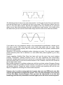
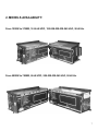
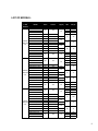
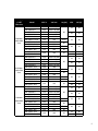
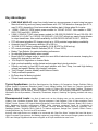
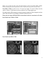
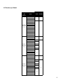
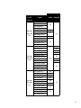
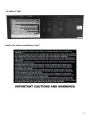
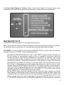
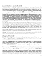
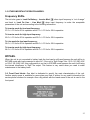
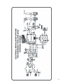
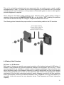
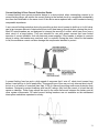
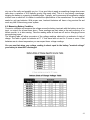
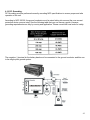
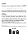
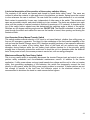
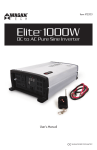
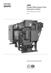
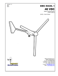
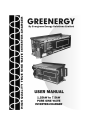
-2- CONTENT 1. INTRODUCTION 2. MODELS AVAILABILITY 3. INDICATORS, CONTROLS AND CONNECTIONS 3.1. Lateral Left-Side Panel 3.2. Lateral Right-Side Panel 3.3. Top Side 3.4. Front Panel Display & Controls 3.5. Other Important Operation Modes 3.6. Front Panel Labels 4. INSTALLATION 4.1. Unit Location & Mounting Procedures 4.2. Placement of Batteries 4.3. Physical Connection of the Batteries 4.4. Battery Cable Protection 4.5. Battery Bank Size 4.6 Backup Time Calculations 4.7. Lead-Acid Battery Types 4.8. Caring for Lead-Acid Batteries 4.9. Measuring Battery Conditions 4.10. AC Grounding 4.11. AC Wiring 4.12. Rotary Switches 5. USEFUL ADVICES 6. TECHNICAL SPECIFICATIONS 7. WARRANTY POLICY 8. TECHNICAL INFORMATION DISCLAIMER 5 7 11 11 12 16 18 25 25 26 28 28 29 30 37 39 40 41 42 43 43 43 45 46 47 47 -3- -4- 1. INTRODUCTION. Evergreen Energy Solutions Limited has developed a very reliable True Pure Sine Wave Inverter-Charger technology with prices comparable to the typical “Modified Step Sine Wave” products broadly used today. After big design efforts, the Corporation has launched the “GREENERGY” GSW Series True Pure Sine Wave Inverter-Charger which is now the most reliable technology able to handle the most exigent and heaviest loads today. Evergreen Energy Solutions Limited, during more than two years, has spent a lot of technical and component resources developing the best protection circuits, smarter and highest current battery charger algorithms and strongest DC-AC Inverter full bridge modulation software in order to provide a product that, despite others in the market, is really well protected against overload and short-circuit conditions, with minimum output voltage distortion vs. load connected and with a very strong and “green” power factor correction battery charger circuit. And of course, the best price/benefit ratio. PURE SINE WAVE VS. MODIFIED STEP SINE WAVE. Please look at the two inverter wave forms showed below. The inverter wave form starts at zero voltage going up, it then starts back down passes zero to the negative peak and then on to the next zero voltage going up. This is called one cycle or a hertz. Normally there are 60 or 50 of these cycles or 60/50 hertz per second in a sine wave depending of the country. The picture bellow is an AC inverter modified sine wave form. If you notice it has a step up, step across, and step down form. It is like the crude square wave form because it clips the tops and bottoms off the wave making a flat and is either strait up or down when going to the positive or negative side ends. It just has an extra step at zero voltage. These flat spots in the wave form is where the hammering sound comes from in electric motors and the noise you hear in some radios. An electric motor or compressor will not have as long of a life using this type of inverter wave form. We can resume the potential problems you can found using Modified sine wave inverters as follow: Radio hum. Lines on television screens. Buzzing of fluorescent lights, dimmer switches, and ceiling fans. Malfunctioning of electronic controls. Increased heating of transformers and electric motors. Lowered performance and efficiency and shortened life span of electric motors, etc. -5- The following picture is from a true sine wave inverter. It is the type of wave form you would see from the city electric grid. It is what that you find in your home. This is the type of wave form you find in a True sine wave inverter. Smooth and rounded all the way. Motors will run quiet and radios will not have the interference like with a modified sine wave inverter. Just looking at the two wave forms you can see how much better things would run with a true sine wave inverter. If you want to run your equipment exactly to the manufacturer‟s specifications, choose a true sine wave inverter. With true sine wave, motor loads start easier and run cooler. Some equipment only operates properly with true sine wave power like laser printers, variable speed motors and digital clocks. Waveform is an important consideration when choosing an inverter. Pure sine wave inverters provide premium power that is identical to or even better than power supplied by your utility company. Frankly speaking, Modified Sine Wave has been until now the wave form most inverters produce. Ultramodern washing machines and a few other appliances with electronically controlled, variable-speed motors won't work at all on mod-sine power, and some people in this field come down hard on mod-sine inverters because of this. However, mod-sine isn't as bad as all this might make it seem. Most people experience no problems whatsoever with their mod-sine system: Evergreen Energy Solutions Limited also provides mod-sine inverters to be great for low cost, off-grid homes and grid backup systems. Despite the claims, mod-sine inverters work perfectly well with the vast majority of appliances including most stereos and computers. However, why to continue using mod-sine inverters when our new GSW series can offer now the best performance with similar prices? This is the key advantage of our new line of Pure Sine Wave Inverter-Chargers. Now you have the opportunity to use the best technology with the best performance because higher prices are not an excuse anymore. 6 2. MODELS AVAILABILITY. From 1250W to 3750W, 12-24-48 VDC, 120-208-220-230-240 VAC, 50-60 Hz. From 5000W to 7500W, 24-48 VDC, 208-220-230-240 VAC, 50-60 Hz. 7 LIST OF MODELS: Power (W) +/- 10% Tolerance 1250 Max 1000-1100 Cont 2500 Max 2000-2200 Cont 3750 Max 3000-3300 Cont Model GSW-1250-12 GSW-1250-24 GSW-1250-48 GSW-1250-2-12-A GSW-1250-2/5-12-B GSW-1250-2-12-C GSW-1250-2-24-A GSW-1250-2/5-24-B GSW-1250-2-24-C GSW-1250-2-48-A GSW-1250-2/5-48-B GSW-1250-2-48-C GSW-1250-5-12-A GSW-1250-5-24-A GSW-1250-5-48-A GSW-2500-12 GSW-2500-24 GSW-2500-48 GSW-2500-2-12-A GSW-2500-2/5-12-B GSW-2500-2-12-C GSW-2500-2-24-A GSW-2500-2/5-24-B GSW-2500-2-24-C GSW-2500-2-48-A GSW-2500-2/5-48-B GSW-2500-2-48-C GSW-2500-5-12-A GSW-2500-5-24-A GSW-2500-5-48-A GSW-3750-12 GSW-3750-24 GSW-3750-48 GSW-3750-2-12-A GSW-3750-2/5-12-B GSW-3750-2-12-C GSW-3750-2-24-A GSW-3750-2/5-24-B GSW-3750-2-24-C GSW-3750-2-48-A GSW-3750-2/5-48-B GSW-3750-2-48-C GSW-3750-5-12-A GSW-3750-5-24-A GSW-3750-5-48-A VAC in VAC out 120 120 208 220 240 208 220 240 208 220 240 208 220 240 208 220 240 208 220 240 230 230 120 120 208 220 240 208 220 240 208 220 240 208 220 240 208 220 240 208 220 240 230 230 120 120 208 220 240 208 220 240 208 220 240 208 220 240 208 220 240 208 220 240 230 230 Freq (Hz) 60 50-60 VDC IDC (A) 12 24 48 40 20 10 12 40 24 20 48 10 12 24 48 12 24 48 40 20 10 70 35 18 12 70 24 35 48 18 12 24 48 12 24 48 70 35 18 100 50 25 12 100 24 50 48 25 12 24 48 100 50 25 60 50-60 60 50-60 60 50 60 50-60 60 50-60 60 50-60 60 50 60 50-60 60 50-60 60 50-60 60 50 8 Power (W) +/- 10% Tolerance 5000 Max 4000-4400 Cont 6250 Max 5000-5500 Cont 7500 Max 6000-6600 Cont Model GSW-5000-24-A GSW-5000-24-B GSW-5000-48-A GSW-5000-48-B GSW-5000-2-24-A GSW-5000-2/5-24-B GSW-5000-2-24-C GSW-5000-2-48-A GSW-5000-2/5-48-B GSW-5000-2-48-C GSW-5000-5-24-A GSW-5000-5-48-A GSW-6250-24-A GSW-6250-24-B GSW-6250-48-A GSW-6250-48-B GSW-6250-2-24-A GSW-6250-2/5-24-B GSW-6250-2-24-C GSW-6250-2-48-A GSW-6250-2/5-48-B GSW-6250-2-48-C GSW-6250-5-24-A GSW-6250-5-48-A GSW-7500-24-A GSW-7500-24-B GSW-7500-48-A GSW-7500-48-B GSW-7500-2-24-A GSW-7500-2/5-24-B GSW-7500-2-24-C GSW-7500-2-48-A GSW-7500-2/5-48-B GSW-7500-2-48-C GSW-7500-5-24-A GSW-7500-5-48-A VAC in VAC out 220 240 220 240 208 220 240 208 220 240 110-0-110 (220) 120-0-120 (240) 110-0-110 (220) 120-0-120 (240) 208 220 240 208 220 240 230 230 220 240 220 240 208 220 240 208 220 240 110-0-110 (220) 120-0-120 (240) 110-0-110 (220) 120-0-120 (240) 208 220 240 208 220 240 230 230 220 240 220 240 208 220 240 208 220 240 110-0-110 (220) 120-0-120 (240) 110-0-110 (220) 120-0-120 (240) 208 220 240 208 220 240 230 230 Freq (Hz) 60 50-60 VDC IDC (A) 24 60 48 30 24 60 48 30 24 48 60 30 24 70 48 35 24 70 48 35 24 48 70 35 24 80 48 40 24 80 48 40 24 48 80 40 60 50-60 60 50 60 50-60 60 50-60 60 50 60 50-60 60 50-60 60 50 9 Key Advantages: PURE SINE WAVE AC output form totally based on microprocessors to avoid using low pass filters built with big and very heavy transformers with 15% THD distortion Average (min 6-7%, max 15-20%) depending of load connected and battery bank Voltage when On Inverter. 1.25kW, 2.5kW & 3.75kW output power models for 120VAC IN-OUT. Also models in 208V, 220V, 230V and 240V, 50/60 Hz. 5.0kW, 6.25kW & 7.5kW output power models for 208-220-230-240VAC IN and 120-0(N)-120 (240VAC L1-L2) OUT or 110-0(N)-110 (220VAC L1-L2) OUT without any need of extra inverter or output transformer. Also models availability for 208-220-230-240VAC IN-OUT, 50/60 Hz. PFC with smart algorithm DC charger circuit up to 100A provides longer backup availability. Automatic Input AC frequency detection (50 or 60 Hz). 12, 24 & 48 VDC battery voltage availability (24 & 48 VDC for 5kW and up). DC current percentage Selector Switches (25, 50, 75 and 100%) Battery Type Selector for maximum battery performance. No charging Mode availability when needed. Broad input AC voltage range to match the most difficult electrical environments, keeping the battery fully charged for more time. 10% Output AC regulation on Inverter Mode. High overload capability and the fastest and strongest short-circuit protection. Friendly and easy to read LED front panel indicator with Over-Temp, Low and High battery voltage and special “Battery fully charged” indicators. “Only Charger” (Inverter disable) mode Selector Switch. Totally automatic operation. By Pass when fail feature included. Private brand name availability. Typical Applications: Cell Sites, Bank Agencies, Gas Stations, Oil Companies, Campus Facilities, Drilling Control Systems, Government: Education, Health, County, Military facilities, Civil Works, etc. Factories, Agriculture (Farms & Cattle), Parking Lots, Movie Theatres, Homes & Trailers (RV), Mobil Health Facilities, Physicians Consulting offices, Hotel & Resorts, Security Systems, Fire Stations, Civil Emergency Assistance, Department & Wholesales Stores-Supermarkets, Pharmacies, Restaurants, Airports, Gambling and gaming premises and many others... Recommended Loads: Any kind of loads such as the following ones can be connected to the unit. Lighting, Fans, Ventilation Systems, Drills, Telecom equipment, Cash Registers, Point of Sales machines, Road Signals, Control Systems, Life Support Medical Equipment, Home Audio & Video Equipment, Boats & RV‟s (indoor use), Appliances (including microwaves), ATM‟s, Office electronic equipment, Small Air Conditioners & Refrigerators, Gas Pumping, Facsimiles, PC, Printers, Servers, Networks, Alarms (security) equipment, AntiSabotage Systems, Telephone PBX‟s, Radio & TV Stations equipment, Garage Door Systems, Electric Fences, Vending Machines, any True On Line UPS and others. Inclusive other loads that are not suitable to be connected with “Step Sine Wave” inverters like Irons Hair-dryers, Hydro Pneumatic Pump systems, Arc-Welding equipment, Large Motors, other Inverter-Charger systems and some UPS‟s and Voltage Regulators that cannot recognize as AC input modified sine wave forms. 10 3. INDICATORS, CONTROLS AND CONNECTIONS. All indicators, controls and connections are conveniently located over each side of the unit: 3.1. Lateral Left-Side panel: Shows battery bank terminal connections and warning messages. Also the Battery Charging Current Selector Switch is included to let you choose the charging current for your battery bank as a percentage of the maximum one. An external ground terminal to ease wiring ground is also provided. The Battery Terminal Connector “label” let you know the right VDC battery bank value for the unit. Please be sure to connect the right battery bank voltage according to this “label”. One Fan, controlled electronically, is conveniently placed in this side to help heat dissipation. 11 Two detailed photos of the Battery Charging Current Selector Switch and ground terminal are shown bellow. For the Battery Charging Current Selector Switch you can choose 25%, 50%, 75% or 100% of the maximum battery charger current as follow (the Selector Switch is factory set in 25%): Please refer to INSTALLATION chapter for instructions about proper connection of battery cables and ground pin. 3.2. Lateral Right-Side Panel: Shows the AC input and output voltage terminal block, as well as the breakers for protecting the load and the battery charger circuit. There is further reference in the INSTALLATION chapter. There are several warning and proper connection instruction “labels”. From 1.25kW to 3.75kW all models are of the same size (smaller) and form. Cables access to the equipment is covered by a metal case matching the color of the unit by means of two orifices suited for that purpose complying with NEC: differentiating input from output voltage. Two breakers are 12 shown: one to protect the load in line mode and another to protect the system‟s battery charger. Stickers indicating the electrical parameters of the unit and the wire connections are also shown. From 5kW to 7.5kW all models are also of the same size (bigger). The panel is different than the used for 1.25kW to 3.75kW because include an additional Fan to handle bigger power. All models include a DB9 connector for external connection towards an external diagnosis interface option. When this option is not available no connector is placed on the unit. Please refer the chapter INSTALLATION for instructions for the best connection for AC cables. Panel Details from 1.25kW to 3.75kW: Panel Details from 5kW to 7.5kW: 13 AC Breakers per Model: AC Breakers (Amps) Power (W) +/- 10% Tolerance 1250 Max 1000-1100 Cont 2500 Max 2000-2200 Cont 3750 Max 3000-3300 Cont Model GSW-1250-12 GSW-1250-24 GSW-1250-48 GSW-1250-2-12-A GSW-1250-2/5-12-B GSW-1250-2-12-C GSW-1250-2-24-A GSW-1250-2/5-24-B GSW-1250-2-24-C GSW-1250-2-48-A GSW-1250-2/5-48-B GSW-1250-2-48-C GSW-1250-5-12-A GSW-1250-5-24-A GSW-1250-5-48-A GSW-2500-12 GSW-2500-24 GSW-2500-48 GSW-2500-2-12-A GSW-2500-2/5-12-B GSW-2500-2-12-C GSW-2500-2-24-A GSW-2500-2/5-24-B GSW-2500-2-24-C GSW-2500-2-48-A GSW-2500-2/5-48-B GSW-2500-2-48-C GSW-2500-5-12-A GSW-2500-5-24-A GSW-2500-5-48-A GSW-3750-12 GSW-3750-24 GSW-3750-48 GSW-3750-2-12-A GSW-3750-2/5-12-B GSW-3750-2-12-C GSW-3750-2-24-A GSW-3750-2/5-24-B GSW-3750-2-24-C GSW-3750-2-48-A GSW-3750-2/5-48-B GSW-3750-2-48-C GSW-3750-5-12-A GSW-3750-5-24-A GSW-3750-5-48-A LOAD CHARGER 10 7 7 4 20 10 16 10 16 10 16 7 10 30 16 20 16 20 16 20 10 16 14 AC Breakers Power (W) +/- 10% Tolerance 5000 Max 4000-4400 Cont 6250 Max 5000-5500 Cont 7500 Max 6000-6600 Cont Model GSW-5000-24-A GSW-5000-24-B GSW-5000-48-A GSW-5000-48-B GSW-5000-2-24-A GSW-5000-2/5-24-B GSW-5000-2-24-C GSW-5000-2-48-A GSW-5000-2/5-48-B GSW-5000-2-48-C GSW-5000-5-24-A GSW-5000-5-48-A GSW-6250-24-A GSW-6250-24-B GSW-6250-48-A GSW-6250-48-B GSW-6250-2-24-A GSW-6250-2/5-24-B GSW-6250-2-24-C GSW-6250-2-48-A GSW-6250-2/5-48-B GSW-6250-2-48-C GSW-6250-5-24-A GSW-6250-5-48-A GSW-7500-24-A GSW-7500-24-B GSW-7500-48-A GSW-7500-48-B GSW-7500-2-24-A GSW-7500-2/5-24-B GSW-7500-2-24-C GSW-7500-2-48-A GSW-7500-2/5-48-B GSW-7500-2-48-C GSW-7500-5-24-A GSW-7500-5-48-A LOAD CHARGER 20 30 20 10 30 20 16 10 16 10 16 30 10 16 10 40 30 40 30 40 30 16 40 30 15 In-detail features of every label: Label for Technical Specifications: Available in this side of the unit for 1.25kW to 3.75kW models, for bigger power models this label is located on the top side of the unit. Label indicating connections to the input terminal: For (-5) Models For (-2) Models single voltage output For (-2) Models double voltage output For 120V models 3.3. Top Side: An important Cautions and Warning messages “label” is printed on the top side of the unit. The high wattage units (5kW and up) also include a sticker for electrical parameters on this side. A sticker with the serial number of the unit is also placed on this side in the right inferior corner. For 1.25kW to 3.75kW: 16 For 5kW to 7.5kW: Detail of the Caution and Warning “label”: 17 3.4. Front Panel Display & Controls: Sleek Frontal Panel Display & Controls allows status modification and monitoring through some light indicators, one switch and one potentiometer. MASTER SWITCH . The MASTER SWITCH located in the front panel has 3 positions: ON: In this position the Inverter-Charger is activated to operate automatically for backing up the load. All operations, alarms, protections, etc., described bellow can take place under this stage. OFF-RESET: You can turn OFF the unit placing the MASTER SWITCH to this position. But the most important function is as “RESET” Switch as described below: A) Placing the MASTER SWITCH from “ON” to “OFF-RESET” position and then ON again, let the unit restores to Inverter-Mode operation after an overload or short-circuit event has occurred and the AC output has been suppressed or turning OFF for protection, that is when an excessive load has been connected to the unit or/and when the unit is servicing a load exceeding its capacity or when internal temperature of the unit goes too high. This could take place when the unit sustains an overload of more than 125% of the nominal current for more than 30 min or, instantaneously, if it were greater than 150% of the nominal current or shortcircuited. Place the MASTER SWITCH from “ON” to “OFF-RESET” position to check the alarm. Once the situation causing overload, short-circuit or over-temperature has been corrected or eliminated, place the MASTER SWITCH from “OFF-RESET” to “ON” position again and the unit will resume then to Inverter Mode without any problem. B) This RESET feature has other important function. When the output voltage from inverter mode (battery) is automatically turned off because the battery reached the lower voltage point permitted by the unit to protect the battery from deep discharges and the input AC power is still absent, you can restore the inverter mode again by placing the MASTER SWITCH from “ON” to “OFF-RESET” position and then to ON position again after you could disconnect some loads 18 according to your needs. This function is very useful because you can deliver more power from the battery bank disconnecting some non critical loads when needed. C) Also when the unit working in Line Mode (AC input is OK and batteries are being charging) if the battery reach a high level of DC Voltage, the load will be turned OFF by the unit to avoid battery continues being overcharged maybe for a failure condition in the battery charger circuit or maybe because some battery or several batteries are damaged. Once the unit protects the load and the total system from this fail, you can turn OFF the MASTER SWITCH to solve the failure issue and then to turn ON again to keep working as usual. Only Charger-Inverter Disable: In this position the MASTER SWITCHT disables Inverter-Mode (On Battery) operation of the unit, leaving the system operating only on Charging-Mode and the load is disconnected from the unit. This feature is selected to operate and control the unit on Inverter-Mode avoiding unnecessary discharges from the battery bank; such as when going away for the weekend and insuring a fully charged battery bank upon coming back. Load On Line – Line Mode . This green indicator is lit when input voltage is inside of the AC operation range of the unit signaling acceptable values of the electrical facility for the load connected and protected. In this case the load is protected against high-energy over-voltages by an internal Surge Suppressor System and extreme AC input voltages. Outside of this range, the unit interprets an abnormal input AC voltage and automatically switches, in a very fast manner, to Inverter-Mode, making it compatible with most computer systems loads; therefore granting the corresponding energy backup. In this case the light on this indicator goes OFF and the yellow indicator Load on Battery – Inverter Mode lights up simultaneously. In this mode the batteries are being charged by the Smart Charger PFC circuit. Note: Calibration range of input AC voltage has been designed for units to be installed in locations where electricity is highly unstable or blackouts are long and frequent. In this way the circuit battery charger is able to operate for a longer period of time furnishing higher backup availability. Notwithstanding, some loads could generate operation failures when connected to such extreme voltages. Input AC Voltage Range for every Input AC Nominal Voltage Models Input Nominal AC Voltage 120V 208V 220V 230V 240V Input Voltage AC Range 90V-136V 156V-235V 165V-250V 172V-260V 180V-272V 19 Load On Battery – Inverter Mode . This yellow indicator is lit when the unit goes to Inverter-Mode when the voltage delivered by utility power is out of the Input Voltage Range (see table above). In this case, the unit proceeds to convert direct voltage (DC) from the battery-bank (12, 24 or 48 VDC) to AC Backup Voltage of 120, 208, 220, 110-0-110 (220), 230, 240 or 120-0-120 (240) VAC, 50-60 Hertz (according to the unit model). At the same time the green Load On Line – Line Mode power supply is outside the unit‟s operation limit. indicator switches “OFF”, signaling that utility Extremely care must be taken to check that the MASTER SWITCH is in “ON” position in order to insure that when transfer takes place the unit has the availability of AC voltage activated to the load on Inverter-Mode (On Battery). The transfer from Line-Mode to Inverter-Mode is automatic. This transfer is accomplished by means of a high-current and reliable transfer relay and by the contribution of a high-speed input-voltage detection system allowing transfer for high as well as for low voltages. The transfer time is typically 10-15 milliseconds. This transfer time is compatible with most of computer and telecom loads. That is the reason this unit is widely used as an Uninterruptible Power Supply (UPS). Once AC utility stabilizes and after a delay reconnection time of 15 seconds, to avoid unnecessary and consecutive “rebounds” from line to inverter and vice-versa, retransfer of the load takes place in approximately 10-15 milliseconds. Simultaneously, the smart battery charger system is activated so as to recharge the battery bank, insuring permanent maximum backup availability in the shortest time possible. IS VERY IMPORTANT TO REMARK THAT THIS UNIT IS ABLE TO CHARGE THE BATTERY BANK IN ALL INPUT AC VOLTAGE RANGE. Others units from competition are only able to charge the batteries in a very narrow input AC voltage range decreasing the backup time availability dramatically in those places where brownouts are very frequent. Warning: The faster transfer time is guaranteed for an input voltage range of 100V-130V. For wider input voltage range the transfer time can reach up to 20-25 ms or more. Charging Batteries . The Smart battery charger of the unit is based in a “3-stage” algorithm as explained below: This green indicator is lit when batteries are in the first and second charging stages of the “3-stage” circuit charger (EQUALIZATION and ACCEPTANCE). The first one, EQUALIZATION is that the charger is charging the batteries at a limited and constant current (maximum value) up to a maximum VDC value which is set up by the Potentiometer BATTERY TYPE SELECTOR . The microprocessor will measure the time that the battery needs to reach the EQUALIZATION voltage and let‟s name this time as “Te” (time to equalization). The second stage (ACCEPTANCE) deactivates the limited and constant current process of the first stage, and proceeds to charge the battery bank with the amount of current it demands (variable) and with a constant voltage as EQUALIZATION values set up initially by Potentiometer BATTERY TYPE SELECTOR , during a time Ta=10 x Te (time of acceptance). During these two firsts charging stages and when this green LED Charging Batteries is always ON indicating that the battery bank is always under charging mode, the charger has been designed to replenish the energy lost by the battery bank from a previous discharge, sulfates adhered to the lead plates are released, the 20 potentials of each cell are evened out, and the electrolyte is actively mixed. The “Ta” timer has a minimum of 1 hour and a maximum of 12 hours. If during these 2 initial stages the unit goes to Inverter Mode and back to On Line mode, the timer is reset restarting the cycle. Then, this LED will be turned OFF once the “Ta” time is finished. Battery Bank Fully Charged . This LED is turned ON when the battery bank has been fully charged and this will occur under the third stage of the Smart Battery Charger named FLOATATION. Flotation is a constant-voltage and variable-current stage set by means of the corresponding Potentiometer BATTERY TYPE SELECTOR . It keeps the battery bank in a constant voltage lower than that of equalization for a period of time of up to 10 days, after that, the microprocessor will reset the cycle restarting the process. In this stage, the battery bank has the highest capacity to deliver maximum current providing optimum backup for the load connected. This stage is also deactivates when the unit is turned OFF by MASTER SWITCH . Once the unit is turned ON again, the process starts all over again. The value of the maximum charging current for every model has been shown before in the LIST OF MODELS. This unit has been designed to provide a very high charging current in order to use battery banks with the maximum possible quantity of batteries to ensure longest backup availability in zones where electricity is not available for many hours. So, having strong battery charging system let you to charge the batteries faster. However, in order to ensure the batteries last longer, always is recommended to charge the batteries with a charging current no more than 25% of the capacity in A/H of the connected battery bank. Now let’s explain the main alarms that cause the unit stop giving power under Inverter-Mode. Very High Internal Temperature . This red indicator is lit when the unit on Inverter-Mode reaches an internal temperature above its normal operating limit. Once this indicator is “ON”, Inverter-Mode operation is automatically disabled and the load is “OFF”. If energy is not restored, the unit can be restarted automatically on Inverter Mode using the OFF-RESET position of the MASTER SWITCH . Should the problem persist, that is if this LED is turned ON again, please check the following conditions: - Dust or obstruction of the ventilation grids or fans. - Non proper operation of the fans. - Temperatures in the environment that may exceed the specified operation values. - It could also be that the unit has been operating for an extensive time above 100% or below 110% of its nominal capacity without engaging in the overload mode (typically after 1 to 2 hours in environments around 25oC). That may happen because the unit withstands 110% overloads, neither engaging in an overload state nor activating the temperature detector. Warning: Should this frequently occur please recheck the connected loads. 21 Inverter Overloaded . This unit is designed to deliver continuous NOMINAL power (24 hr per 365 days a year) but also possesses an extraordinary capability for handling overloads, withstanding loads of up to 110% of its nominal capacity continuously, and up to 150% for 20-30 seconds. This overload capability is very useful to start loads from DC battery bank (no utility present) especially those demanding high startup current, like refrigeration equipment and power lighting systems. Should overload exceed time limit, the unit automatically protects the inverter by shutting it down and signaling this status by means of this LED. Once the situation causing the overload is fixed, the OFF-RESET function of the MASTER SWITCH can be used to restore Inverter-Mode operation. The overload light indicator should be “OFF” once the cause of the situation is normalized. A special Overload condition is the Short-Circuit on Inverter-Mode. A short-circuit is interpreted by the unit as an Overload condition of more than 150% of the nominal continuous power. Should a shot-circuit occur on the output of the unit on Inverter-Mode, the unit will protect itself automatically making a shutdown of the AC output voltage while the short-circuit condition is still present. The unit could be restarted only upon detecting and solving the short-circuit cause and then using the OFFRESET function of the MASTER SWITCH to restore Inverter-Mode operation. The overload light indicator should be “OFF” once the cause of the situation is normalized. If by any circumstance a failure arises preventing normal operation of the overload detector, the internal temperature inside the unit will increase rapidly due to the handling of high short-circuit current by the power elements of the inverter-circuit, then over-temperature protection will step in completely deactivating Inverter-Mode operation. NOTE: The unit is protected from overloads and short-circuits also in line-mode. That is, when utility is under working range and the loads exceed the equipment power rating. Upon this condition the “overload” protection breaker on the lateral left-side panel is triggered. In addition, should there be a failure in the system battery charger circuit that increases considerably the current on the charger circuit above the maximum limit; it also triggers the charger AC breaker, also placed on the lateral left-side panel. Warning: DO NOT ATTEMPT TO RESTORE THE INVERTER MODE IF ALARM “OVERLOAD” LIGHT IS ON. THIS ACTION CAN CAUSE A LOT OF UNNECESSARY STRESS OVER THE INVERTER CIRCUIT SECTION. High Battery Voltage (Overcharged) - - - If this condition is detected by the unit, the output load, in On Line Mode will be turned OFF and the battery charging process will be stopped. This condition is a “major alarm” making this LED flashing. As “major alarm” is recommended to check deeply the condition of each battery of the battery bank and also the operation of the battery charger to check is one of them or both could be damaged. Once the issue is solved, the OFF-RESET function of the MASTER SWITCH used to restore On Line operation. can be 22 Low Battery Voltage (Discharged) _____ The same red indicator is lit continuously when the battery bank reaches the “impending shutdown DC voltage” of the battery bank. It signals that the battery bank is next to the shutdown voltage limit and an imminent AC voltage interruption from the DC-AC inverter circuit, while backup is taking place soon. An audible alarm will also sound. Please check below the battery DC voltage setting points for all models: Low Battery Impending Shutdown Alarm: 10.5 VDC +/- 0.3 VDC for 12V systems. 21.0 VDC +/- 0.6 VDC for 24V systems. 42.0 VDC +/- 0.6 VDC for 48V systems. Low Battery Shutdown: 10.0 VDC +/- 0.3 VDC for 12V systems. 20.0 VDC +/- 0.6 VDC for 24V systems. 40.0 VDC +/- 0.6 VDC for 48V systems. High Battery Voltage Shutdown Alarm: 16.0 VDC +/- 0.3 VDC for 12V systems. 32.0 VDC +/- 0.6 VDC for 24V systems. 64.0 VDC +/- 0.6 VDC for 48V systems. High Battery Voltage Recovery Point: 15.5 VDC +/- 0.3 VDC for 12V systems. 31.0 VDC +/- 0.6 VDC for 24V systems. 62.0 VDC +/- 0.6 VDC for 48V systems. BATTERY TYPE SELECTOR This Potentiometer is very useful to increase the life expectancy of the battery bank connected giving them the proper charging voltages according their construction and manufacturer specifications. Some battery types may look confusing such as GEL USA and GEL EURO, AGM USA and AGM EURO. If in doubt call your battery supplier and ask which charge voltage they want you to use for their battery type, and select the closest to it according to the table below. If totally confused, then use the lower voltage setting (1) until you have had the right voltage setting confirmed. There are two important settings for this Potentiometer: The “No-Charging” mode (0) and the “Manual Equalization” mode (8). The “Not-Charging” mode is very useful when you want to use this unit only as DC to AC Inverter that is in locations where already exist battery banks charged by external Rectifiers for example (telecom). Then you can deactivate the “charging mode” using the potentiometer in this position. The “Manual Equalization” mode or “de-sulphatation cycle” on potentiometer in position (8) is a procedure that needs special attention and should be done by specialized technicians. 23 Before even attempting to use this cycle you must clearly understand what it does and when and how you would use it. What causes sulphatation? This can occur with infrequent use of the batteries or if the batteries have been left discharged so low that they will not accept a new charging procedure. This cycle is very high voltage charge cycle designed to try to break down the sulphate „crust‟ that is preventing the plates taking a charge and thus allow the plates to clean up and so accept charge once again. How to use this function? - Please be aware that this process is only suitable for open lead acid batteries. - Ensure the battery bank is totally isolated from anything else. The high voltage applied by this setting could destroy all your electronics and other electrical equipment still connected, so - Make sure the battery compartment is very well ventilated and battery caps are removed. - Switch the battery type selector to the correct position and then switch the AC power on. - Because this is very delicate setting there is a 4 hour time out period builds into the software for this process, however on a very large battery bank this may not be enough and the unit may need to be switched OFF and ON again to do another cycle. What to expect on this cycle? We would recommend you monitor the voltage of the sulphated battery bank during all process. When you switch on the cycle the voltage should shoot up to the full 15.5 (31 or 62) volts very fast (within minutes) this is because the batteries cannot accept the charge (assuming they are sulphated). However, over a period of 1~2 hrs the voltage should start to drop (as the plates start to clean and the batteries start to take charge) then the voltage could drop way down to about 12.5 (25 or 50) volts then start to rise. These shows the batteries are now taking a charge and starting to fill up. In this case it would be safe to switch the unit OFF and select your normal charging curve and hopefully this will bring your batteries back from the bad condition. You may need to repeat the process a few times. Please note this is a professional guess tool, which most times helps, but it is not magic, so expect the worst and hope for the best. Never leave a system unattended when on this mode. If the battery temperature reaches above 50 Celsius degree (ie. if the batteries are almost too hot to touch) then stop the process. Potentiometer Position 0 1 2 3 4 5 6 7 8 9 Battery Type or Action EQUALIZATION Voltage FLOATATION Voltage 12V 24V 48V 12V 24V 48V NO CHARGING MODE AVAILABLE, UNIT USED ONLY AS DC-AC INVERTER GEL USA 14.0 28.0 56.0 13.7 27.4 54.8 AGM TYPE 1 14.1 28.2 56.4 13.4 26.8 53.6 AGM TYPE 2 14.6 29.2 58.4 13.7 27.4 54.8 SEALED LEAD ACID 14.4 28.8 57.6 13.6 27.2 54.4 GEL EURO 14.4 28.8 57.6 13.8 27.6 55.2 OPEN LEAD ACID 14.8 29.6 58.2 13.3 26.6 53.2 CALCIUM 15.1 30.2 60.4 13.6 27.2 54.4 MANUAL EQUAL 15.5 31.0 62.0 DURING 4 HOURS THEN OFF NOT USED THE POTENTIOMETER IS FACTORY PRESET IN POSITION 1 24 3.5. OTHER IMPORTANT OPERATION MODES. Frequency Shifts. The unit also goes to Load On Battery – Inverter Mode when input frequency is “out of range” and back to Load On Line – Line Mode when input frequency is under the acceptable parameters of the unit and according to the following information: To inverter mode for low input frequency: 57.0 +/- 0.3 Hz for 60 Hz operation and 47.0 +/- 0.3 Hz for 50 Hz operation. To Inverter mode for high input frequency: 65.0 +/- 0.3 Hz for 60 Hz operation and 55.0 +/- 0.3 Hz for 50 Hz operation. To Line mode for low input frequency: 58.0 +/- 0.3 Hz for 60 Hz operation and 48.0 +/- 0.3 Hz for 50 Hz operation. To Inverter mode for high input frequency: 64.0 +/- 0.3 Hz for 60 Hz operation and 54.0 +/- 0.3 Hz for 50 Hz operation. BYPASS. When the unit is not connected to battery bank the load can be still used because the unit will be in BYPASS mode with load connected to input AC. If the unit is “Split Output” like 110-0-110 (220) VAC or 120-0-120 (240) VAC, this configuration is not lost in BYPASS mode because the unit is still using the internal transformer to “Split” the output. This feature is very useful when you need to make maintenance to the battery bank. 3.6. Front Panel labels: One label is dedicated to specify the main characteristics of the unit. Another empty space is available for users place any kind of sticker for any useful information like service phone numbers for example. Also a big sticker with the brand name of the unit is used in the front panel. 25 4. INSTALLATION. Qualified technical personnel must install this unit, any faulty installation could impair proper operation and cause damages not covered under the warranty. Next page shows a typical general diagram for this class of equipment, including: - A manual Rotary Switch to connect the AC input of the unit to the utility power or to an emergency generator. This is a very suitable and low-cost option in comparison to an automatic transfer switch. - Another manual Rotary Switch to bypass the unit if necessary or specifically when undergoing service maintenance or there is a frequent low AC voltage in the network preventing proper charge operation of the unit since this will often be on inverter mode. - According to the NEC, there are two ways the battery bank could be connected to the inverter: the first and most recommended is by means of a UL- approved Class T DC fuse plus an element for disconnection, such as an Anderson connector; the second one is a DC breaker for disconnection. The reasons to consider the first option (Class T DC Fuse) as the best one will be explained in detail further on. - The combination of the unit with alternative power system such as wind or solar arrays is only for informational purposes. For further information regarding these applications please consult your provider. - AC panel breakers for input and output cable distribution. 26 27 4.1. Unit Location and Mounting procedures. The unit must be installed in a freshly ventilated area, protected from atmospheric elements such as: sunlight, water, humidity, etc. and out of gases released by non-sealed batteries from the battery bank. Never place the unit outdoors. The unit is designed to be horizontally mounted. Secure the unit to a wall or to a rack using the keyholes placed in the base of the equipment. Make sure to face and able to see clearly the indicators and controls of the display and that the potentiometers can be handled easily for technician. This is heavy equipment, so all mounting keyholes must be secured and firmly attached to the supporting element. Allow enough room around the unit for ventilation and handling. Do not place unit on close to the floor, the internal fan will easily pick-up all the dust in the room and it will make it circulate inside of the unit and it may cause short-circuit, fan failures or damages to the circuitry not covered under this warranty. An internal fan cools the unit. Special care must be taken to insure that the grids for incoming air are free and unclogged, and also to prevent battery gases (from non-sealed batteries) from reaching the unit‟s interior. Follow all directions on the top side panel of the equipment as explained before. 4.2. Placement of the batteries Batteries for long backup system storage a great quantity of energy and then are capable of delivering peak currents of hundreds of amperes. Such large amount of current has an unthinkable destructive power for the end user for that is very counterproductive a careless handling of the batteries. That is why the following recommendations will help diminish the chances of accidents in environments with batteries: Make installation of the unit as well of the battery bank by certified and authorized technical personnel. Do not connect the battery bank until you have read and understood all instructions and warnings in this user manual. Check for technician‟s proper connection of batteries. The unit requires high power-supply from the batteries; therefore it is very important to insure correct operation of the unit that connections between the unit and the batteries are made with the adequate terminals and cables of the right caliber, keeping the length of the cables as short as possible. This will prevent overheating and voltage-drop in the cables and terminals. Keep in mind that voltage drops in the cables and in loose connections prevents availability of the full capacity of the batteries. Loose connections also accelerate sulfurization, making the problem worst. When the batteries are sealed maintenance-free to keep them connected as close to the unit as possible is best in order to minimize voltage-drop in the cables. When the choice is non-sealed batteries, it is just the opposite; these must be connected in a ventilated and as far as possible location (but not too much to avoid voltage drops in the cables). Corrosive gases might cause health problems and they could also attack any electronic equipment or 28 metal they contact. Nevertheless, this effect can be minimized by selecting minimum maintenance and gas release non-sealed batteries. Wet cell batteries must be periodically checked to adjust the water level. Therefore, easy-access to their location should be insured. Since airflow in the unit is right to left, should this kind of batteries be placed under the unit they must be placed to its left, in order to minimize battery-released gases inside the unit. Install batteries in a relative high place (but within user‟s reach); therefore keeping low the risk of any metal object dropping on top of them, so as to avoid short-circuiting the terminals. Do not place batteries touching the floor directly, this accelerates loss of electrolyte. Notwithstanding the kind of batteries, insure that maximum distance between the unit and the batteries do not exceed 10-feet using the maximum caliber possible. Should there be any physical contact between any non-protected body-part and the batteries, please wash exposed body area as immediately. And please, place batteries in an area out of the reach of children. 4.3. Physical Connection of the Batteries. Battery Terminals. Observe the following instructions when connecting battery cables to the unit battery terminals: The unit is not reverse-polarity protected. Reversing polarity on the battery DC input connectors will cause permanent damages to the unit which is not covered by the warranty. Always check polarity before making those connections. Ensure that MASTER SWITCH is on the position “OFF” disabling the operation of the unit on Inverter-Mode before connecting or disconnecting the battery cables, and that AC input power is disconnected from the AC input connector. Battery cables must have been crimped (or preferably, soldered and crimped) cooper compression lugs. The connections that are only soldered are not acceptable. Place the ring terminal over the bolt and directly against the unit battery terminal. Tighten the 5/16” nut to 10-15 foot/pounds torque. Do not place anything between battery cable ring terminals and terminals on the unit. The terminal stud is not designed to carry current. Is a good practice to apply anti-oxidant paste to terminals after them have been tightened. Connecting the battery cables to the DC terminals will cause an arc, usually accompanied by a “snap”. This is normal. There is no reason to be scared or alarmed. 29 This unit is not ignition protected and uses components that can produce arcs o sparks, usually accompanied by a “snap”. To reduce the risk of fire or explosion, do not install the unit in non-vented confined spaces close to batteries or in the presence of flammable gases or areas in which ignition protected equipment is required. Never disconnect the battery cables while the unit is delivering power or when battery charger is operating. Always ensure that MASTER SWITCH is on the position “OFF” disabling the operation of the unit first and that the input AC voltage is totally disconnected from the unit. The following picture illustrates the proper method to connect battery cables to the DC terminals. 4.4. Battery Cable Protection DC Fuses vs. DC Breakers. Both types of devices can provide over-current protection of the battery bank and its DC wiring. A breaker is often preferred, as it can also operate as a switch to turn the power “ON” and “OFF”. Fuses are less popular but are available in a greater variety of designs and ratings. Fuses should be used with a disconnect switch or an Anderson connector (or similar) which allows the fuse to be changed without being electrically "hot". Fuses are less expensive than breakers and generally the required combination of the fuse with a disconnect switch or special Anderson connector is still less expensive than a good breaker. However, the decision between Fuses or Breakers is not only cost related. It is necessary to take into account two very important issues: Time Response and Current Interruption Capacity. 30 Current Limiting & Over-Current Protective Device A current-limiting over-current protective device is a device which, when interrupting currents in its current-limiting range, will reduce the current flowing in the faulted circuit to a magnitude substantially less than that obtainable in the same circuit if the device were replaced with a solid conductor having comparable impedance. A non-current limiting protective device by permitting a short-circuit current to build up to its full value; can let an immense amount of destructive short-circuit heat energy through before opening the circuit. Most DC-rated breakers are not designed to interrupt the amount of current, which can occur from a short circuit of a large battery. They are intended for use with power sources that have limited amounts of current available, such as electronic power supplies. If the breaker is subject to currents above its rating, the breaker may overheat, melt, or explode. During the time it takes for the breaker to fail, the excessive current can also damage the components intended to protect. A current limiting fuse has such a high speed of response that it cuts off short-circuit current long before it can build up to its full peak value. This special type of fuse can not only interrupt short-circuit, but do so in a fraction of a second (less than 1/120 of a second) providing much more protection than breakers. Designed to protect breakers with low-AIC ratings, they limit the current to a level that will cause no damage. These fuses should be used in the main disconnect between the battery and all other system components. DC-rated current limiting breakers are not available as the mechanical interruption mechanism operates too slowly. 31 DC Fuse Types. The recommended DC fuse for these applications is the Class T Fuse. Class T Fuses are very fast blow for electronic and electrical circuit protection. They are available in a wide range of Amp values, but the most commonly used in any typical installations are from 110 Amp to 400 Amp. All of these have the bolt-on lugs. The fuses are industry standard, and are UL listed. Class T fuses are required in many code applications as they are rated for 160 volts DC with an arc interrupt rating of 20.000 amps. Class T fuses are very stoutly constructed and must successfully open the circuit without arcing (as well as preventing self-destruction) to protect the battery bank and the battery cable. They are also considered as "very fast acting". Class T fuses is designed to smooth the arc generated when the fusible material melts during an overload or short circuit. Class T DC Fuse T Fuse-Holder There is another type of DC Fuses. ANN fuses are very popular for using between a long backup UPS or inverter-charger and battery bank due to they are an economical alternative to Class T fuses in a non-code installation. ANN fuses are not UL listed; however ANN fuses from 35 to 400 amps are UL approved. If it is desirable to adhere to the NEC for interruption capacity, use Class T fuses or High AIC DC Breakers. The ANN fuse holder holds all sizes of ANN fuses. ANN fuses are available in sizes from 100 to 400 amps to match any power application. ANN DC Fuse ANN Fuse-Holder DC Fuses Installation Guides. Always put the fuse (or circuit breaker) in the wiring as close to the battery as possible. The less unprotected wire (the wire between the battery and the circuit breaker or fuse) the better. Also, never bypass a fuse or circuit breaker that keeps blowing. There is a reason that this is happening. Who wants to come home to a street filled with fire trucks? It is better to shut everything down until you find and correct the problem than it is to give your neighbors a place to roast their marshmallows. The DC Fuse must be installed in the positive (+) battery terminal using a shortest cable for that purpose (maximum 18 inches). An appropriate fuse holder must be also used. The following pages contain both, a technical datasheet of a Class T fuse and ANN fuse and their respective fuse holders. 32 33 34 Anderson Connectors. In order to replace any DC fuse opened due to short-circuit or when in need of a quick disconnection of the battery bank, a manual easy to activate sectioning battery system with a very low resistance should be in place. Anderson connectors are recommended (also they are the most widely used) for these situations. On the next pages there is a technical datasheet of these connectors corresponding to the SB models. Please let a certified technician to recommend the proper types of fuses and Anderson connectors for every GREENERGY Inverter-Charger model. Anderson connector + DC battery wiring Metallic Clip for Anderson connector Pair of Anderson connectors 35 36 4.5. Battery Bank Size. The size of the battery bank required depends on the storage capacity required, the maximum discharge rate, the maximum charge rate, and the minimum temperature at which the batteries will be used. When designing a power system, all of these factors are looked at, and the one requiring the largest capacity will dictate battery size. One of the biggest mistakes made by those just starting out it does not understand the relationship between amps and amp-hour requirements of 120 volt AC items versus the effects on their DC low voltage batteries. For example, let say you have a 24 volt nominal system powering a load of 3 Amps, 120 VAC, which has a duty cycle of 4 hours per day. You would have a 12 AH load (3A x 4 hrs=12 AH). However, In order to determine the true drain on your batteries you have to divide your nominal battery voltage (24V) into the voltage of the load (120V), which is 5, and then multiply this times your Amp hours (12 AH). So, in this case, the calculation would be 60 AH drained from your batteries (not the 12 AH). There are other factors for determining the full extent of the battery drain, such as temperature, start-up factors, etc., but this should help you get a more complete picture on how to size your low voltage batteries when powering 120/240 volt loads using a long backup UPS (invertercharger). Temperature has a significant effect on lead-acid batteries. At 40°oF they will have about 75% of rated capacity, and at 0°oF their capacity drops to about 50%. The storage capacity of a battery, the amount of electrical energy it can hold, is usually expressed in Amp Hours (AH). If 1 Amp is used for 100 hours, then 100 AH have been used. A battery in a solar power system should have sufficient AH capacity to supply needed power during the longest expected period "no sun" or extremely cloudy conditions. In wind systems allowance for "no wind" days should be included. A lead-acid battery should be sized at least 20% larger than this amount. If there is a source of backup power, such as a standby generator along with a battery charger, the battery bank does not have to be sized for worst-case weather conditions. NOTE: It is recommended to keep the battery bank homogeneous, since connecting in series batteries of different type, brand, service time, etc. or to connect new batteries to used ones, damaged, or just with different characteristics, tends to rapidly damage batteries initially in good shape. And remember: Any adjustment of the unit must be carry out by qualified technical personnel. Series Wiring Series wiring refers to connecting batteries to increase VOLTS, but not amps. If you have two 12 volt batteries rated at 105 amp hours, for example, by connecting the positive terminal of one battery to the negative terminal of the other, then you have series wired the two together. In this case, you now have a 24 volt battery and the rated 105 amps do not change. If you were to series wire four 12V105AH batteries you'd have 48 volts at 105 amps, and so on. 37 Parallel Wiring. Parallel wiring refers to connecting batteries to increase AMPS, but not volts. If you have two 12 volt batteries rated at 105 amp hours, for example, by connecting the positive terminal of one battery to the positive terminal of the other, and the same with the negative terminal, then you have parallel wired the two together. In this case, you now have a 12-volt battery and the rated 105 amp increases to 210 amp hours. Series - Parallel Wiring If you need to series wire two 105AH battery you'd have 24 volts at 105 amps. If you have two sets of 24 volts at 105 amps and then parallel wire these two sets, then you'd have a 24-volt battery at 210 amps. When longer backup times are required an alternative is to connect additional battery banks in parallel. Nevertheless, longer backup time means that for the same charge-current the time it takes to recharge is also longer; therefore diminishing backup availability. In this case, the rule to follow is to readjust (increase) the charge-current, trying to keep the simple rule that the OPTIMUM chargecurrent must equal a 25% AH capacity of the battery bank already connected. If this cannot be 38 possible due to the large size of the connected battery bank and the capacity to handle currents of the battery charge is rather large but limited, it is recommended to recur to an external battery charger connected in parallel to the unit circuit charger. It is recommended to perform this kind of arrangement with properly qualified and certified personnel. 4.6. Backup Time Calculations. In order to simplify how to choose the size of the battery bank you need, you can use the following table. First, calculate the total load you need to backup. Second, please estimate the backup time. Then, look for the nearest intersection point between these two data and the table will say you how many batteries you will need approximately. 4.7. Lead-Acid Battery Types. Lead-acid batteries are the most common in Inverter-Charger systems because their initial cost is lower and are readily available nearly everywhere in the world. There are many different sizes and designs of lead-acid batteries, but the most important designation is whether they are DEEP CYCLE batteries or shallow cycle batteries 39 Shallow cycle batteries, like the type used as start-up batteries in automobiles, are designed to supply a large amount of current for a short time and withstand mild overcharge without loss of electrolyte. Unfortunately, they cannot tolerate being deeply discharged. If they are repeatedly discharged more than 20 percent, their expected life will be very short. These batteries are not a good choice for Inverter-Charger systems. DEEP CYCLE batteries are designed to be repeatedly discharged by as much as 80 percent of their capacity so they are a good choice for power systems. Even though they are designed to withstand deep cycling, these batteries will have a longer life if the cycles are shallower. All lead-acid batteries will fail prematurely if they are not recharged completely after each cycle. Letting a lead-acid battery stay in a discharged condition for many days at a time will cause sulfating of the positive plate and a permanent loss of capacity. SEALED DEEP CYCLE lead-acid batteries are maintenance free. They never need watering or equalization charge. They cannot freeze or spill, so they can be mounted in any position. Sealed batteries require very accurate control to prevent overcharge and over-discharge. Either of these conditions will drastically shorten their lives. It is especially recommended sealed batteries for remote, unattended power systems (like Telecom cell sites) but also for any client desiring maintenance free feature not minding the extra-cost associated to these batteries. Conclusion: If location is a very critical factor and physical security is mandatory, Sealed DeepCycle Maintenance-Free batteries are recommended; should financial reasons prevail, wet-cell deep cycle batteries is recommended, keeping in mind in the selection those that release gases and require maintenance to the minimum. 4.8. Caring For Lead-Acid Batteries. Always use extreme caution when handling batteries and electrolyte. Wear gloves, goggles and old clothes. "Battery acid” will burn skin and eyes and destroy cotton and wool clothing. The quickest way to ruin lead-acid batteries is to discharge them deeply and leave them stand "dead" for an extended period of time. When they discharge, there is a chemical change in the positive plates of the battery. They change from lead oxide when charged to lead sulfate when discharged. If they remain in the lead sulfate stay for a few days, some part of the plate does not return to lead oxide when the battery is recharged. If the battery remains discharged longer, a greater amount of the positive plate will remain lead sulfate. The parts of the plates that become "sulfated" no longer store energy. Batteries that are deeply discharged, and then charged partially on a regular basis can fail in less than one year. Check your batteries on a regular basis to be sure they are getting charged. Use a hydrometer to check the specific gravity of your lead acid batteries. If batteries are cycled very deeply and then recharged quickly, the specific gravity reading will be lower than it should because the electrolyte at the top of the battery may not have mixed with the "charged" electrolyte. Check the electrolyte level in wet-cell batteries at least four times a year and top each cell off with distilled water. Do not add water to discharged batteries. Electrolyte is absorbed when batteries are much discharged. If you add water at this time, and then recharge the battery, electrolyte will overflow and make a mess. Keep the tops of your batteries clean and check that cables are tight. Do not tighten or remove cables while charging or discharging. Any spark around batteries can cause a hydrogen explosion inside and 40 ruin one of the cells, and possibly you too. It is a good idea to apply an equalizing charge when some cells show a variation of 0.05 specific gravity from each other. This is a long steady overcharge, bringing the battery to a gassing or bubbling state. Typically, we'll recommend an equalization charge at least once a month but it is better to consult the specification of the manufacturer. Do not equalize sealed or gel type batteries. With proper care, lead-acid batteries will have a long service life and work very well in almost any power system. 4.9. Measuring Battery Condition. Connect a voltmeter and measure the voltage across the battery terminals with the battery at rest (no input, no output) for at least three hours. These readings are best taken in the early morning, at or before sunrise, or in late evening. Take the reading while all loads are off and no charging sources are producing power. The following table will allow conversion of the voltage readings obtained to an estimate of state of o charge. The table is good for batteries at 77 F that have been at rest for 3 hours or more. If the batteries are at a lower temperature you can expect lower voltage readings. You can see that when your voltage reading is about equal to the battery "nominal voltage" your battery is about 60% discharged. 41 4.10. DC Grounding. DC Grounding must be performed correctly according NEC specifications to ensure proper and safe operation of the unit. According to NEC 250-95, the ground conductor must be sized taking into account the over-current protection device you are using. See the following table that you can use as a guide. However, grounding requirements can vary by country and application. Please consult the local code for safety. The negative (-) terminal ok the battery bank must be connected to the ground conductor and this one to the single point ground system. 42 4.11. AC Wiring. General. In a chapter above, a diagram corresponding to the lateral left side panel of each GREENERGY model was shown. Directions for connecting phase, neutral, and ground as AC input as well as AC output are clearly marked for those terminals. Please consult the NEC or your local electric code for greater accuracy about which wires must be used for every Inverter-Charger Model. Please let certified technicians to do this job for you. These units handle relatively high input currents since all power is delivered to the connected load while at the same time recharging the battery bank. In order to deliver these currents the input should be wired with cables as short as possible, of the right caliber, and connected straight to the breaker distribution board with a protection breaker. Using cables too thin and too long would cause voltagedrop that may deform the output wave while batteries are being charged, and also a high fire risk due to overheating. Cable Connections. When connecting wires or cables to any of the safety or control devices please remember that connections should be clean and tight, this cannot be overemphasized. If they are not clean, heating can result, due to high resistance. If they are not tight, arcing can result. Most failures are due to improper installation. And don't forget to check the tightness of the connections from time to time. Most of the UL listed items have a torque range listing on their labels. Cable lugs should be made of copper for the lowest electrical resistance. When you purchase cable lugs, there are some cheap ones out there. Why spend big money on your photovoltaic, wind or hydro generators, InvertersChargers, controls and batteries then scrimp on what is an essential item? When every bit of efficiency is important, don't give some of it up by trying to save pennies on your connectors. WARNING: Do not connect AC input to AC output in any unit model. This is known as “back feeding” and will damage the unit. In this case warranty will not apply. This situation is typically found when Rotary Transfer Switches are connected in the wrong way in some installations. 4.12. Rotary Switches. On before pages the installation schematic of two manual transfer switches with their specific function was shown. Rotary Switches 43 A technical description of the operation of these rotary switches follows: The contacts of the switch are opened and closed by round disks called "cams". The cams are notched to allow the contacts to open and close in the positions you desire. Spring forces the contact to close wherever the cam is notched. The cam holds the contact open wherever it is not notched. Each contact is operated by its own cam, independent of other cams in the switch. The contacts and cams are mounted in decks, each deck holding up to two contacts. The decks are stacked onto each other until the number of required contacts is reached (a maximum of 16 contacts). A chamber at the top of the switch holds a special cam that determines the switching angle or detent of the switch. Switches are 45 degree switching angle and are ON-OFF-ON. The handle is attached to a shaft that goes through the switch and rotates the cams as the handle is turned, thus opening and closing the contacts at wish. Line-Generator Rotary Manual Transfer Switch This switch enables manual selection of AC input to unit upon blackout, whether from utility power or from an AC emergency generator. The idea is to take advantage of the fast-transfer capability of the unit and use the Inverter-Charger as an UPS; therefore avoiding purchase of an expensive automatic transfer switch or a resize of the battery bank. Most of the loads will not perceive any energy disruption during blackout while the unit battery bank delivers backup for a few minutes, giving enough time to manually activate this switch and to hook the unit to a generator while the blackout lasts. Once power is back, the reverse process is carried out, with no energy disruption. Maintenance Manual By-Pass Rotary Switch. This is a very useful switch to completely disconnect the inverter-Charger input and output in order to perform safely scheduled and non-scheduled maintenance service. In addition to the former application, if utility power shows a strong trend towards low-voltage and the unit is often on inverter mode, thus preventing recharging of the batteries; this switch can temporarily connect the load directly to utility power, while the utility power supply problem is corrected. If these switches are not fast enough to transfer of the load from the inverter‟s output to the electrical network, it is recommended to shutdown the loads in a safe manner before bypass. 44 5. USEFUL ADVICES. During blackouts connect the Inverter-Charger only to loads that are strictly necessary. When going away for long-time periods and in no need of backup, disable automatic transfer by means of the MASTER SWITCH in Only Charging-Inverter Disabled. Extend batteries service life, do not turn all connected loads to the unit on simultaneously, this will diminish discharge from the batteries and also increase longer backup time. Try using low-power efficient lightning as it may produce a similar level of luminosity to that of conventional lightning (neon lamps and light bulbs). Although it is not a problem for the GREENERGY GSW Series to handle inductive loads, such as motors (refrigerators), it is recommended to take into account that these kinds of loads require very high start-up currents that may cause an overload to the unit. Should an overload occur while on inverter mode, make sure to detect and solve the problem before restarting the unit since multiple restarts lead to unnecessary overheating of the inverter section, therefore causing damages to the unit not covered under this warranty. 45 6. TECHNICAL SPECIFICATIONS. GSW-7500(-A)(-B) GSW-6250(-A)(-B) GSW-5000(-A)(-B) GSW-3750(-A)(-B) GSW-2500(-A)(-B) GSW-1250(-A)(-B) 7.50 kW 6.25 kW 5.00 kW 3.75 kW 2.50 kW 1.25 kW 6.60 kW 5.50 kW 4.40 kW 3.30 kW 2.20 kW 1.10 kW 9.00 kW 7.50 kW 6.00 kW 5.00 kW 3.00 kW 1.50 kW OUTPUT Maximun Power (30 min) Continuous Power Surge Power (20 sec) Nominal Voltage (Inverter Mode) Nominal Current (120/240V) (-A) (-B) models Transfer Time Inverter Waveform Frequency (Inverter Mode) Power Factor allowed AC-AC Efficiency DC-AC Efficiency 120 VAC (208-220 VAC) (230 VAC) +/- 10%. 120 VAC models only up to 3.75KW. 240 VAC (208-220 VAC) (230 VAC) +/- 10% for 5000, 6250 & 7500 models 240 VAC full power/120 VAC two taps half power (also same configuration for 220/110 VAC) for 5000, 6250 & 7500 models 120V or 110V output voltage also available in Line mode and By-Pass condition for 5000, 6250 & 7500 models 27.5 (30.0) (28.7) Amp 22.9 (25.0) (23.9) Amp 18.3 (20.0) (19.1) Amp 27.5 (15.0) (14.3) Amp 18.3 (10.0) (9.6) Amp 11.0 (5.0) (4.8) Amp Inverter-Line: 8-12 ms, Line-Inverter: 10-15 ms. Compatible with most computer loads True Sine Wave with average 10-15% THD voltage 60 (60) (50) Hz; +/- 0.3Hz. Inverter output full synchronized with input AC frequency (locked). 0 to 1 96% typical @ for continuous power 88% to 90% typical @ for continuous power INPUT Transfer AC Voltage to Inverter mode For 120V models: Min=90V. Max=136V. For 220V models: Min=165V. Max=250V For 240V models: Min=180V. Max=272V. For 230V models: Min=172V. Max=260V Transfer AC Voltage to Line mode For 240V models: Min=190V. Max=264V. For 230V models: Min=182V. Max=253V AC Frequency Max AC Current including Charger All voltages +/- 4% For 120V models: Min=95V. Max=132V. For 220V models: Min=174V. Max=242V All voltages +/- 4% From 47 Hz to 55 Hz for 50 Hz input. 57 Hz to 65 Hz for 60 Hz input. Out of these ranges, unit goes to inverter mode. Input frequency is auto-detected 34.6 (37.7) (36.1) Amp 31.1 (34.0) (32.5) Amp 25.4 (27.7) (26.5) Amp 39.3 (21.4) (20.4) Amp 26.6 (14.5) (13.9) Amp 15.7 (7.6) (7.3) Amp PROTECTIONS Low and High battery Voltage Autorecovery when AC input back Delay Reconnection from Inverter to Line Yes, 2 stages: Audible alarm when DC voltage reach 10.5-21-42V & Inverter shutoff when DC voltage reach 10-20-40V. Inverter mode electronic Overload Inverter mode electronic Shortcircuit Inverter mode electronic Overtemp Reset function Recommended external Input AC breaker Inverter Disable Mode Air Cooling For load >120% (Surge Power) Inmediate output shut off including short-circuit. Master Switch must be "Reset" to re-start the inverter Yes, when DC voltage reach Minimum Start Battery Voltage 15 Seg. Yes, Inverter shutoff inmediately. Main Switch must Reset to re-start the inverter Yes, Inverter Shut off. Auto-Restore when Overtemp situation disappear Yes, to re-start the inverter after that Overload & Shortcircuit situation disappear 45 (45) (45) Amp 40 (40) (40) Amp 30 (30) (30) Amp 50 (25) (25) Amp 40 (20) (20) Amp 20 (10) (10) Amp Yes (Manual Sleep Mode for minimum DC power consumption) Yes, Forced, electronically controlled CHARGER & BATTERIES DC Nominal Voltage/Current 24V/80A, 48V/40A 24V/70A, 48V/35A 24V/60A, 48V/30A 12V/100A, 24V/50A, 48V/25A 12V/70A, 24V/35A, 48V/18A 12V/40A, 24V/20A, 48V/10A 12, 24 or 48 VDC up to 3750 models. 24 or 48 VDC for the rest. Every model only with one battery voltage. Battery Current Adjustment Battery DC Power without load (Stand-By) SW1 On = 25% of total. SW1 and SW2 On = 50% of Total. SW1 and SW2 and SW3 On = 75% of Total. All Switches OFF = 100% Recommended Input DC battery fuse (12VDC) Recommended Input DC battery fuse (24VDC) Recommended Input DC battery fuse (48VDC) Battery Charging modes Inverter Off Low Battery Voltage Inverter Off High Battery Voltage Minimum Start Battery Voltage Battery Type Selector (Type=Abs/Float) NA NA NA 400 Amp 300 Amp 150 Amp 400 Amp 400 Amp 300 Amp 225 Amp 150 Amp 75 Amp 25 W aproximately. Just 2% of the maximum power rate for 1.25kW models and 0.33% for 7.5kW models. Excellent for Solar Applications 225 Amp 200 Amp 150 Amp NA NA Automatic 3 stages: 1- Equalization (constant current). 2- Acceptance or Absorbtion (Constant Voltage). 3-Floatation. NA For 12VDC= 10V. For 24VDC= 20V. For 48VDC=40V For 12VDC= 16V. For 24VDC= 32V. For 48VDC=64V For 12VDC= 11V. For 24VDC= 22V. For 48VDC=44V Gel USA=14.0/13.7. AGM1=14.1/13.4. AGM2=14.6/13.7. Sealed Lead Acid=14.4/13.6. Gel Euro=14.4/13.8. Open Lead acid:14.8/13.3. Calcium=15.1/13.6. (x2 for 24V and x4 for 48V) PHYSICALS Input and Output connections Battery Bank connections External Ground Pin Connector Wall mount capability Special packing for export Operating Temperature Relative Humidity Storage Temperature Anticorrosive protection for Circuit boards Audible Noise Safety and Quality Approvals Aproximate gross weight without packaging Dimensions (H x W x D) mm (unit) Terminal Block (Hardwired). 120V & 230V models: Li, Ni, G, No, Lo. 220V models: L1i, L2i, G, No, Lo. 240V models: L1i, L2i, G, No, L1o, L2o. Terminal Block covered by metal cover. Steel terminals with fire retardant plastic color coded covers Yes Yes Yes 0o C to 50º C 5% to 95% non condensing -15º to 60º C Yes 60 dB max CE (EN60950), FCC Class A, EN50091-2 Class A, compliance with UL 458, ISO-9001 40 kg 598 x 218 x 179 38 kg 35 kg 22 kg 442 x 218 x 179 20 kg 18 kg CONTROLS & INDICATORS LED'S Master Switch Green=AC Line In Range (Line Mode), Yellow=Load on Inverter (Inverter Mode). Green= Battery Charging (1st&2nd Stage). Green= Battery Fully Charged (3rd Stage or Floating). Red=Internal Over Temperature. Red= Overload. Red= Low Battery Voltage (ON) and High Battery Voltage (Blinking). Three (3) positions Inverter Disable, Unit ON and Unit OFF or Reset after shutdown 46 7. WARRANTY POLICY. Our Factory only sells products throughout distributor‟s channels and guarantees all products to the distributors by covering only the repair o replacement procedure of any damaged part of the unit, for the time-period expressed in the distributor‟s invoice. We will honor our warranty to our distributors thru our RMA format. The end user is subjected to the own distributor‟s warranty format. Please consult your provider about its warranty terms. However, for all products, any warranty format for end users will never cover: Damages than can occur to external equipment or devices, as well as any compensation for dismissed lucre. Damages caused by external facts like: fire, water, generalized corrosion, biological infestations and by input voltages that create operating conditions beyond the maximum or minimum limits listed in the product specifications including high input voltage from generators and lightning strikes. Damages caused by transportation. Normal wear and tear of the product, and costs related to the removal, installation or troubleshooting of the customer‟s electrical systems. Damages caused by mistakes during installation procedures. When unit presents repairing intention by NOT AUTHORIZED personnel. When the explosion of any component of the surge suppression circuit causes any internal or external damage to the unit, in which case, the company considered the unit was operating correctly. When the original identification markings of the product (trade-mark, serial number) have been defaced, altered or removed. All products featured in this user manual are easy to install. However, please make sure that licensed electricians verify the installation and follow all instructions indicated in the product user‟s manuals and/or any “special instructions” written in the standard packages of the products. 8. TECHNICAL INFORMATION DISCLAIMER. Any technical information displayed in the company‟s web page or in any written paper, catalog or user manual can be changed without previous notice. The company makes not warranty as to the accuracy, sufficiency or suitability of any technical or other information provided in any product manual or other documentation not of its own. Furthermore, our company assumes no responsibility or liability for loss or damage, whether direct, indirect, consequential or incidental, which might arise out of the use of such information. The use of any such information will be entirely at the user‟s or distributor‟s risk. All products‟ catalogs can be downloaded from the company‟s web page. Some technical documents are also available to supplement the product information. Photos of some products would be slightly different of the final product you would receive. 47 48