Download Setting Jitter/Wander Parameters

Transcript
Setting Jitter/Wander Parameters
This section gives examples of how to work with Jitter/Wander test
setups; Setting Jitter or Wander Generation; Setting Jitter Receive
Parameters; and, Calibrating Jitter Systems.
Refer also to the Telecommunications Technology section within
the Appendices (located on reference on CD)for theory of operation
information on Jitter & Wander.
CTS850 SDH/PDH Test Set
Jitter/Wander Working with Test Setups
You can use the CTS850 to run the following types of jitter
conformance tests:
H Jitter Tolerance
H Jitter Transfer
H Output Jitter
H Pointer Jitter (SDH rates only)
In each of these tests, the CTS850 measures the jitter on a signal at
the output of a network element. For some tests, the CTS850
generates jitter to stimulate the network or a network element while
it simultaneously measures the network response.
CTS850 SDH/PDH Test Set User Manual
3 159
Setting Jitter/Wander Parameters
Figure 3 65:Example of TEST SETUP, Jitter & Wander screen
Before selecting a jitter test, set the specific jitter generation and
measurement rates and payloads required by the test. For example, to
perform an output jitter test on an STM 1 signal, set the receive line
rate to STM 1 before selecting test setups.
It is not necessary to set the jitter and wander TRANSMIT or
RECEIVE settings, since this is done automatically by the CTS850
software, depnding on the test type.
When the test is complete, you can save the results, print the results,
or export the results data to bring into a spreadsheet. Refer to
“Saving and Recalling Setups” later in this section for more
information.
Setting Up a Jitter Test
To set up a jitter test:
1. If the jitter test requires the test set to measure jitter, use the
RECEIVE menu to set the receive parameters that are appropriate
for the signal you will be measuring. Refer to Setting SDH
Receive Parameters for information about this topic.
3 160
CTS850 SDH/PDH Test Set User Manual
Setting Jitter/Wander Parameters
2. If the jitter test requires the CTS850 to generate jitter, use the
TRANSMIT menu to set the transmit parameters that are
appropriate for the signal you will be generating. Refer to Setting
SDH Transmit Parameters for information about this topic.
3. To set the type of jitter test:
Press Menu
Button
Select Menu
Page
Highlight
Parameter
Select Choice
TEST SETUPS
JITTER TESTS
Test Type
Output Jitter
Jitter Tolerance
Jitter Transfer
Pointer Jitter
H Select Output Jitter to measure the jitter at the output of a
network element. (The output jitter test does not use the
CTS850 jitter-generation capability.)
H Select Jitter Tolerance to measure the tolerance of the input
of a network element to applied jitter (this test uses bit error
measurement).
H Select Jitter Transfer to measure the transfer of jitter from
the input to the output of a network element.
H Select Pointer Jitter to measure jitter in PDH signals due to
pointer movement in the SDH signal (this test does not use
jitter generation).
The remaining parameters are dependent on the type of jitter test
you select.
CTS850 SDH/PDH Test Set User Manual
3 161
Setting Jitter/Wander Parameters
Jitter Tolerance Test. Follow these additional steps to set up a jitter
tolerance test.
1. Set the Test Type to Jitter Tolerance and set the mask type as
appropriate. The available masks depend on the rate, as shown in
the table below.
Rate
Available Masks
2 Mbit/s
G.823 (Standard), G.823 (National)
34 Mbit/s
G.823
45 Mbit/s *
G.824
140 Mbit/s
G.823
STM 0
GR 253
STM 1
G.825, G.958 (Type A), G.958 (Type B)
STM 4
G.825, G.958 (Type A), G.958 (Type B)
* If your CTS 850 test set supports the 45 Mb/s option.
The CTS850 modulates the transmitted line or clock frequency with
sinusoidal jitter. The jitter generator begins at the start frequency and
stops at the end frequency.
2. To set the start frequency for the jitter generator:
3 162
Press Menu
Button
Select Menu
Page
Highlight
Parameter
Select Choice
TEST SETUPS
JITTER TESTS
Start Frequency
as appropriate
CTS850 SDH/PDH Test Set User Manual
Setting Jitter/Wander Parameters
3. The available end frequencies are dependent on the current
transmit rate. To set the end frequency for the jitter generator:
Press Menu
Button
Select Menu
Page
Highlight
Parameter
Select Choice
TEST SETUPS
JITTER TESTS
End Frequency
as appropriate
4. The CTS850 can generate jitter at intermediate frequencies
between the start frequency and end frequency. To set the total
number of frequencies generated (including the start and end
frequencies):
Press Menu
Button
Select Menu
Page
Highlight
Parameter
TEST SETUPS
JITTER TESTS
Number Freq
Samples
Select Choice
as appropriate *
* Number of samples change depending on Start/End frequencies.
5. To set the tolerance criteria:
Press Menu
Button
Select Menu
Page
Highlight
Parameter
Select Choice
Press Menu
Button
Select Menu
Page
Highlight
Parameter
Select Choice
TEST SETUPS
JITTER TESTS
Tolerance Criteria
Onset of Errors
BER Penalty
H Select Onset of Errors to define the tolerance as two Errored
Seconds in a 30-second time interval.
H Select BER Penalty to measure the amount of jitter that is
equivalent to a 1 dB loss of signal power at the input of the
network element (optical only).
CTS850 SDH/PDH Test Set User Manual
3 163
Setting Jitter/Wander Parameters
6. If you selected Onset of Errors, skip to step 12. If you selected
BER Penalty, continue with step 7 (see the following figure).
Figure 3 66:Example of TEST SETUP, Jitter Tests, BER Method
7. The CTS850 must be connected to a network element through an
optical attenuator.
8. To set a baseline bit-error rate for the measurement:
Press Menu
Button
Select Menu
Page
Highlight
Parameter
TEST SETUPS
JITTER TESTS
Record Error
Threshold
Select Choice
Measure BER
9. Observe the Current BER and Recommended BER values in the
display. Increase the optical attenuation until the Current BER
reaches or exceeds the Recommended BER.
3 164
CTS850 SDH/PDH Test Set User Manual
Setting Jitter/Wander Parameters
10. When the Current BER equals the Recommended BER to within
an order of magnitude:
Press Menu
Button
Select Menu
Page
Highlight
Parameter
TEST SETUPS
JITTER TESTS
Record Error
Threshold
Select Choice
Record BER
11. Increase the receive level by 1.0 dB (that is, reduce the
attenuation by 1.0 dB).
12. Press the START/STOP button to run the jitter test. The results
are displayed on screen in numerical and graphical form. This
takes about 6 minutes for 6 points.
Transfer Jitter Test. Follow these additional steps to set up a jitter
transfer test.
1. Set Test Type to Jitter Transfer. Set the mask type as follows:
Press Menu
Button
Select Menu
Page
Highlight
Parameter
Select Choice
TEST SETUPS
JITTER TESTS
Mask Type
as appropriate
The available mask types are dependent on the current transmit rate.
The CTS850 modulates the transmitted line with sinusoidal jitter. If
the TX menu sets Jitter Output to Clock, the Jitter Transfer screen
will indicate “Unsupported Settings”. The jitter generator begins at
the start frequency and stops at the end frequency.
2. The available start frequencies are dependant on the current
transmit rate. To set the start frequency for the jitter generator:
Press Menu
Button
Select Menu
Page
Highlight
Parameter
Select Choice
TEST SETUPS
JITTER TESTS
Start Frequency
as appropriate
CTS850 SDH/PDH Test Set User Manual
3 165
Setting Jitter/Wander Parameters
3. The available end frequencies are dependent on the current
transmit rate. To set the end frequency for the jitter generator:
Press Menu
Button
Select Menu
Page
Highlight
Parameter
Select Choice
TEST SETUPS
JITTER TESTS
End Frequency
as appropriate
4. The CTS850 can generate jitter at intermediate frequencies
between the start frequency and end frequency. To set the total
number of frequencies generated (including the start and end
frequencies):
Press Menu
Button
Select Menu
Page
Highlight
Parameter
TEST SETUPS
JITTER TESTS
Number Freq
Samples
Select Choice
as appropriate *
* Points dependent on Start/End frequencies.
NOTE. You can calibrate a 0 dB baseline, as described in ITU T
O.171, prior to measuring transfer jitter if the folllowing conditions
are met: the jitter generation output and measurement input are both
set to line, and if the transmit and receive rates are set to the same
rate. If either of the conditions can not be met, skip to step 10.
5. Verify that the jitter generation output and measurement input are
both set to Line.
6. Verify that the transmit and receive rates are set to the same rate.
3 166
CTS850 SDH/PDH Test Set User Manual
Setting Jitter/Wander Parameters
7. To calibrate a 0 dB baseline:
Press Menu
Button
Select Menu
Page
Highlight
Parameter
Select Choice
TEST SETUPS
JITTER TESTS
Action
Calibrate
8. Press the START/STOP button to run the 0 dB baseline
calibration routine. This takes about 3 minutes.
9. To run the transfer jitter test after the calibration is complete,
press Edit Setup:
Press Menu
Button
Select Menu
Page
Highlight
Parameter
Select Choice
TEST SETUPS
JITTER TESTS
Action
Jitter Transfer
10. Press the START/STOP button to run the jitter transfer test. The
results are displayed on screen in numerical and graphical form.
This takes abouts 4 minutes for 7 samples. Press View Data to see
the data and whether or not the test passed. Press Edit Setup to
return to Main Jitter Test menu.
CTS850 SDH/PDH Test Set User Manual
3 167
Setting Jitter/Wander Parameters
Output Jitter Test. Follow these steps to set up an output jitter test.
1. Set Test Type to Output Jitter. The recommended time duration
for an output jitter test is one minute. To set the test duration to
one minute (or any other duration of your choice),:
Press Menu
Button
Select Menu
Page
Highlight
Parameter
Select Choice
TEST SETUPS
JITTER TESTS
Test Duration
15 sec, 30 sec
1 min, 15 min
USER DEFINED
H Select USER DEFINED to enter a time other than one of the
preset choices. The maximum duration is 99 days, 23 hours,
59 minutes, 59 seconds.
2. Press the START/STOP button once or twice, light should be lit
to run the jitter test. The results are displayed on screen in
numerical form. After the test duration time has passed for each
filter (wideband and highband), compare measured jitter with the
maximum allowed to determine pass or fail. The resolution of
these measurements are 0.001 UIpp.
Pointer Jitter Test. Follow these additional steps to set up a pointer
jitter test. To select Pointer Jitter, the TX must be set to a SDH rate,
and the RX set to a PDH rate.
1. Set Test Type to Pointer Jitter. To set the pointer sequence type:
Press Menu
Button
Select Menu
Page
Highlight
Parameter
Select Choice
TEST SETUPS
JITTER TESTS
Sequence Type
as appropriate
2. Press the START/STOP button to run the jitter test. The results
are displayed on screen in numerical form, after about 6 minutes.
3 168
CTS850 SDH/PDH Test Set User Manual
Setting Jitter/Wander Parameters
Saving and Recalling Results
You can save one jitter test result to disk and recall that one test
result for later display and analysis. If you want to save test results
permanently, you must save the test results to a disk.
The CTS850 saves each type of jitter test result with a unique
file-name extension. Because of the unique extensions, you can
perform different types of jitter tests on a network element and give
them a common results file name.
To save jitter test results:
Press Menu
Button
Select Menu
Page
Highlight
Parameter
Select Choice
TEST SETUPS
JITTER TESTS
Test Control
Save Results
Refer to Saving and Recalling Results for detailed information about
using the disk drive to save and recall results.
Printing Results
You can print jitter test results using the “Print Last Screen” choice
in the Print Control dialog box. Refer to Printing Results for detailed
information about printing.
Exporting Results into a Document
You can export the jitter tolerance and jitter transfer test results in a
Microsoft Excel compatible format to produce a graph for your
documentation. Use the saved files with .XTL or .XTR for this
purpose.
The file format consists of a header that identifies the type of test,
the date and time, the transmit source, the transmit and receive rates,
and the number of sample points in the graph. Data following the
header is comma separated and consists of four values for each
sample point in the graph: modulation frequency, mask amplitude,
measured amplitude, and a status indicator that indicates an
over range condition.
CTS850 SDH/PDH Test Set User Manual
3 169
Setting Jitter/Wander Parameters
Setting Jitter or Wander Generation
To test the response of a network to jitter, you may need to generate
SDH signals, PDH signals, or clock signals that contain jitter. You
can use the CTS850 to generate any of these signals with a
controlled amount of jitter. This jitter is a sinusoidal modulation of
the line rate or clock rate; you can specify the frequency and
amplitude of the jitter.
Wander generation selection is identical to jitter generation except
that it applies for modulation frequencies of 10 Hz or less. See the
following figure.
Figure 3 67:Example of TRANSMIT, Jitter menu
3 170
CTS850 SDH/PDH Test Set User Manual
Setting Jitter/Wander Parameters
NOTE. The jitter compliance tests, available through the JITTER
TESTS page of the TEST SETUPS menu, automatically set the jitter
generation parameters needed for the test. When you use the jitter
compliance tests, you do not need to set the controls described below.
Periodic calibration of the jitter generation system is recommended
to maintain best accuracy. You can execute a built in calibration
routine before making critical measurements. Refer to the Jitter
Calibration information located at the end of the this section.
Turning on Jitter or Wander Generation
To turn on jitter or wander generation:
Press Menu
Button
Select Menu
Page
Highlight
Parameter
TRANSMIT
JITTER &
WANDER
Jitter/Wander
Generation
Select Choice
Off
On
H Select Off to disable jitter/wander generation.
H Select On to enable jitter/wander generation.
CTS850 SDH/PDH Test Set User Manual
3 171
Setting Jitter/Wander Parameters
Selecting the Jitter Output
To select the signal that you want to apply generated jitter to:
Press Menu
Button
Select Menu
Page
Highlight
Parameter
Select Choice
TRANSMIT
JITTER &
WANDER
Jitter Output
Line
Clock 0.8 V
2 MHz G.703
H Select Line to enable generated jitter on the transmitted line
(SDH signal or PDH signal) that comes out of the front panel.
This will also generate jitter on the rear-panel Jitter Clock
Output, even though it may not be in use. Note: for 140 Mbit/s
and STM 1E, line mode rear panel signal is twice the line rate.
H Select Clock 0.8 V to enable generated jitter on the rear-panel
jitter clock output (J/CLK OUT) only (AC-coupled ECL). The
transmitted line remains jitter free.
H Select 2 MHz G.703 to enable generated jitter on the rear-panel
jitter clock output (J/CLK OUT) that meets the interface
requirements for synchronization signals as specified in G.703.
The transmitted SDH or PDH line signal remains jitter free.
You can independently set the Jitter Clock Output rate and frequency
offset, regardless of the line rate and frequency offset of the
transmitted signal. To set an independent rate for the Jitter Clock
Output:
3 172
Press Menu
Button
Select Menu
Page
Highlight
Parameter
Select Choice
TRANSMIT
JITTER &
WANDER
Jitter Output
Clock 0.8V
Jitter Clock Rate
as appropriate
CTS850 SDH/PDH Test Set User Manual
Setting Jitter/Wander Parameters
To set an independent frequency offset for the Jitter Clock Output:
Press Menu
Button
Select Menu
Page
Highlight
Parameter
Select Choice
TRANSMIT
JITTER &
WANDER
Jitter Output
Clock 0.8V
Jitter Clock Offset
as appropriate
Setting the Jitter Frequency and Amplitude
The generated jitter is a sinusoidal modulation of the nominal line or
clock rate. Refer to the Modulation Range specifications for details
about jitter/wander generation capability. To set the modulation
frequency:
Press Menu
Button
Select Menu
Page
Highlight
Parameter
Select Choice
TRANSMIT
JITTER &
WANDER
Jitter Frequency
as appropriate
H Select USER DEFINED to specify a jitter frequency different
from the predefined choices. Use these choices: Course to
adjust most significant digit or change decade scale; Medium to
adjust second digit; Fine to adjust third digit.
NOTE. To generate jitter, set the Jitter Frequency to 10 Hz or greater.
To generate wander, set the Jitter Frequency to less than 10 Hz.
CTS850 SDH/PDH Test Set User Manual
3 173
Setting Jitter/Wander Parameters
To set the modulation amplitude (in unit intervals):
Press Menu
Button
Select Menu
Page
Highlight
Parameter
TRANSMIT
JITTER &
WANDER
Jitter Amplitude
Select Choice
300.00 UI (Max)
150.00 UI (Max/2)
0.0 UI
H Select USER DEFINED to specify a jitter amplitude different
from the predefined choices. Use choices Coarse, Medium or
Fine.
Measure Wander on a 2 MHz clock output from a network element
When generating wander, synchronize the test system to an external
timing source. This can be done by connecting a 2.048 MHz clck to
the rear panel reference timing input and selecting timing source
under TRANSMIT settings. Follow the steps below:
H Connect 2 MHz reference clock to 2 Mbps/ 2 MHz reference
clock input on Rear Panel of test unit.
H Connect External 2 MHz clock to be measured to Jitter/ Clock
input on Rear Panel of test unit.
H Go to TRANSMIT settings. Set the Transmit Clock to 2 MHz
external. The Receive Clock is the Same. No Wander Measurements should be made with Internal Clock.
H Press Start/Stop twice to Start/Restart the test.
H For RESULTS, select the Jitter & Wander Screen, and view
Wander Measurements.
3 174
CTS850 SDH/PDH Test Set User Manual
Setting Jitter/Wander Parameters
Setting Jitter Receive Parameters
You can set the CTS850 to measure jitter or wander on incoming
SDH signals, PDH signals, or clock signals. First, set the jitter
receive parameters below. Then, you can view jitter or wander
measurement results in the Jitter & Wander Results page shown at
the end of this section on Jitter.
Figure 3 68:RECEIVE, Setting Jitter Mode, Peak to Peak
NOTE. The jitter compliance tests, available through the JITTER
TESTS page of the TEST SETUPS menu, automatically set the jitter
receive parameters needed for the test. When you use the jitter
compliance tests, you do not need to set the controls described below.
Periodic calibration of the jitter generation system is recommended
to maintain best accuracy. You can execute a built in calibration
routine before making critical measurements. Refer to the Jitter
Calibration information located at the end of this section.
CTS850 SDH/PDH Test Set User Manual
3 175
Setting Jitter/Wander Parameters
Selecting the Jitter Mode
To select the jitter measurement mode:
Press Menu
Button
Select Menu
Page
Highlight
Parameter
Select Choice
RECEIVE
JITTER &
WANDER
Jitter Mode
Peak-Peak
RMS
H Select Peak-Peak to make peak-to-peak jitter measurements.
H Select RMS to make RMS jitter measurements. If you select
RMS, the only available input filter is a 12 kHz high-pass filter.
Selecting the Input Source
To select the input source on which you want to measure jitter:
Press Menu
Button
Select Menu
Page
Highlight
Parameter
RECEIVE
JITTER &
WANDER
Jitter Input
Source
Select Choice
Line
Clock
H Select Line to measure jitter in the received line (front-panel
SDH or PDH signal) selected in the RECEIVE SETTINGS page.
H Select Clock to measure jitter on the rear-panel external jitter
clock input (J/CLK IN). If you select Clock, you must set the
external jitter clock input rate; that rate does not have to be the
same as the Receive Rate selected in the RECEIVE SETTINGS
page.
3 176
CTS850 SDH/PDH Test Set User Manual
Setting Jitter/Wander Parameters
Selecting the Jitter Range
The jitter range determines the maximum measureable jitter and the
resolution of the measurement. To select the range:
Press Menu
Button
Select Menu
Page
Highlight
Parameter
Select Choice
RECEIVE
JITTER &
WANDER
Jitter Range
Normal
Extended
H Select Normal to measure jitter up to 6 UIp-p with a resolution of
0.005 UI (frequency dependent). Refer to RX Range Mask in
Specifictions section (in Appendix).
H Select Extended to extend the jitter measurement range up to
200 UIp-p (frequency dependent) with a resolution of 0.01 UI.
Selecting the Jitter Input Filter
You can choose from three types of jitter measurement high pass
filters defined by ITU-T standards: wideband, highband, and
fullband. The passbands for the filters, shown in Figure 3 69, are
dependent on the signal or clock rate settings; the 3 dB frequencies
are described in the Specifications located in the Appendices at the
back of this book.
The ITU T standard that applies to jitter input filters is contained in
G.823, Table 1, Measurement Filter Bandwidth.
CTS850 SDH/PDH Test Set User Manual
3 177
Setting Jitter/Wander Parameters
Fullband
Wideband
Highband
Amplitude
Frequency
Figure 3 69:Jitter High PassFilters
To select the jitter input filter:
Press Menu
Button
Select
Menu Page
Highlight
Parameter
RECEIVE
JITTER &
WANDER
Jitter Measurement
Filter
Select Choice
Wideband
Highband
Fullband
H Select Wideband to measure jitter using the wideband measurement filter (500 Hz 1.3 MHz).
H Select Highband to measure jitter using the highband measurement filter (65 kHz 1.3 MHz).
H Select Fullband to measure jitter over the wideband range plus
very low frequency jitter that may affect timing quality for Video,
PBX and GSM systems that derive an internal reference from the
supplied line signal (10 Hz 1.3 MHz).
3 178
CTS850 SDH/PDH Test Set User Manual
Setting Jitter/Wander Parameters
NOTE. Separate Highband National and Highband Standard settings
are available for the 2 Mb/s rate, as referenced in the ITU T
standards.
If you select the Fullband jitter input filter, perform the following
steps to set the filter high-pass frequency:
Press Menu
Button
Select Menu
Page
Highlight
Parameter
RECEIVE
JITTER &
WANDER
Fullband
High-pass
Select Choice
0.1 Hz
1 Hz
10 Hz
Note that the lock time for 1 Hz and 10Hz settings are longer than
other filter settings.
Setting the Jitter Hit Threshold
The jitter hit threshold determines the sensitivity of the Jitter Hit
Seconds measurement, which is based on peak-to-peak jitter.
Jitter Hit Seconds is a count of how many seconds the threshold was
exceeded since the beginning of the the measurement. Measurement
will normally begin between 2 5 seconds after the start button on the
front panel is pressed. You can set the threshold to any value between
0 and 200 UI, depending on the Range Setting.
Whenever the received jitter exceeds the range of the jitter
measurement system, the Current Jitter reads Unlocked. Jitter
Unlocked Seconds is a count of how many seconds the measurement
system has been unlocked since the beginning of the the measurement.
CTS850 SDH/PDH Test Set User Manual
3 179
Setting Jitter/Wander Parameters
To set the jitter hit threshold:
Press Menu
Button
Select Menu
Page
Highlight
Parameter
RECEIVE
JITTER &
WANDER
Jitter Hit
Threshold
Select Choice
as appropriate
H Select USER DEFINED to specify a jitter hit threshold different
from the predefined choices.
Setting the Pointer Hit Threshold
The pointer event threshold (available for PDH rates) determines the
sensitivity of the Jitter Pointer Hits measurement, which is based on
the frequency drift rate. To set the pointer event threshold:
Press Menu
Button
Select Menu
Page
Highlight
Parameter
RECEIVE
JITTER &
WANDER
Pointer Hit
Threshold
Select Choice
as appropriate
H Select USER DEFINED to specify a pointer hit threshold
different from the predefined choices. You can set the threshold
to any value between 0 and 10 ppm/sec.
3 180
CTS850 SDH/PDH Test Set User Manual
Setting Jitter/Wander Parameters
Example of Jitter Measurements
The RESULTS screen for Jitter/ Timing Quality follows.
Figure 3 70:RESULTS, Jitter and Timing Quality
CTS850 SDH/PDH Test Set User Manual
3 181
Setting Jitter/Wander Parameters
Example of Wander Measurements
The “max” value shows the maximum peak to peak,positive peak,
and negative peak since the beginning of the measurement.
When measuring wander, it is necessary to synchronize the test to an
external timing source. This can be done by connecting a 2.048 MHz
clock signal to the rear panel timing input and selecting the
appropriate timing source under the TRANSMIT settings.
The RESULTS screen for Wander/ Line Frequency follows.
Figure 3 71:RESULTS, Wander and Line Frequency
3 182
CTS850 SDH/PDH Test Set User Manual
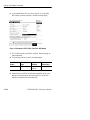
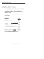
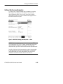
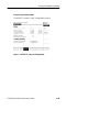
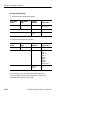
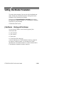
Setting Jitter/Wander Parameters
Calibrating Jitter Systems
Periodic calibration of the jitter generation and measurement systems
is recommended to maintain best accuracy. You can execute built in
Jitter Measurement calibration routines before making critical
measurements.
Run Jitter Measurement before runing Jitter Generation Calibration.
This Jitter Measurement calibration takes about 15 minutes for all
rates. You can calibrate one particular rate by selecting the
appropriate calibration routine.
If your CTS 850 test set supports a 45 Mb/s rate, this screen below
will show that rate in addition to all the others displayed.
Figure 3 72:Example of UTILITY, Jitter Calibration
CTS850 SDH/PDH Test Set User Manual
3 183
Setting Jitter/Wander Parameters
Executing Jitter Calibration
To calibrate the jitter measurement system:
Press Menu
Button
Select Menu
Page
Highlight
Parameter
UTILITY
CALIBRATION
System
Jitter
Measurement
Routine
All
Calibration
Control
Run
Select Choice
To calibrate the jitter generation system:
Press Menu
Button
Select Menu
Page
Highlight
Parameter
Select Choice
UTILITY
CALIBRATION
System
Jitter Generation
Routine
All
STM 0
STM 1
STM 4
2 Mb/s
34 Mb/s
45 Mb/s
140 Mb/s
Analog output
Calibration
Control
Run
Jitter Generation for all rates takes about 45 minutes to run.
A status message indicates that the calibration is running, has
completed and has passed, or has failed.
3 184
CTS850 SDH/PDH Test Set User Manual