1
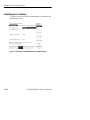
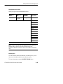
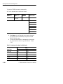
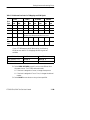
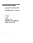
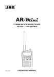
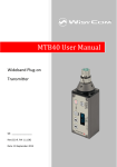
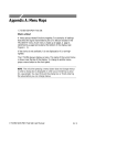
Setting Alarms and Inserting Errors
This section describes how to simulate error conditions, set alarms,
and simulate network failures. To test the response of a network, you
might need to simulate parity errors, send alarm signals, and simulate
network failures. This type of testing is simple and convenient using
the CTS850 SDH/PDH Test Set.
To insert PDH errors, it is necessary to set the layer in the mux chain
where anomalies, defects and failures will be inserted. Some errors,
like CRC, are specific to a particular layer (in this case, 2 Mb/s
Multiframe). Insertion of a layer specific error will not change the
insertion layer. Layer selection is not limited to active tributary rates.
See the example of a TRANSMIT, Defects & Anomalies menu
screen for PDH at the end of this section on how to set the layer for
PDH Anomalies, Defects and Failures.
CTS850 SDH/PDH Test Set User Manual
3 185
Setting Alarms and Inserting Errors
Simulating Error Conditions
The specific errors the CTS850 simulates depend on the transmit rate
and payload structure.
Figure 3 73:Example of TRANSMIT, Defects & Anomalies menu
3 186
CTS850 SDH/PDH Test Set User Manual
Setting Alarms and Inserting Errors
Specifying the Error to Insert
Specify the type of error transmitted as follows:
Press Menu
Button
Select Menu
Page
Highlight
Parameter
Select Choice
TRANSMIT
Defects &
Anomalies
Error type set to
None
RS B1BIP
MS B2BIP
Path B3 BIP
HP REI
TU BIP
TU Path BIP
LP REI
Pattern Bit
PDH FAS Error
PDH FAS Burst
Code
PDH CRC
NOTE. The errors available to insert depend on the Structure and
Payload settings. Not all errors are available all the time.
FAS Burst is defined in terms of M errors in N frames, rather than a
rate.
Inserting Errors
You can choose to insert errors manually (one at a time) or you can
have errors inserted automatically at a rate you specify.
To insert a single error, press the INSERT ERROR button.
CTS850 SDH/PDH Test Set User Manual
3 187
Setting Alarms and Inserting Errors
To have the CTS850 insert errors automatically:
1. Turn on automatic error insertion as follows:
Press Menu
Button
Select Menu
Page
Highlight
Parameter
Select Choice
TRANSMIT
Defects &
Anomalies
Error rate set to
None
1e 3
1e 4
1e 5
1e 6
1e 7
1e 8
USER DEFINED
H Select None to turn off automatic error insertion. However,
you can still insert errors manually using the front-panel
INSERT ERROR button.
H The maximum allowable error rate depends on the transmit
rate, signal structure, and error type (see Tables 3 24 and
3 25).
Table 3 24:Maximum Error Rates for SDH Signals
Rate
3 188
Error Type
STM-1
STM-4
RS B1 BIP
1E 4
1E 5
MS B2 BIP
1E 4
1E 4
Path B3 BIP
1E 4
1E 4
HP REI
1E 4
1E 4
Pattern Bit
1E 3
1E 3
CTS850 SDH/PDH Test Set User Manual
Setting Alarms and Inserting Errors
Table 3 25:Maximum Error Rates for TU Mappings and PDH Signals
N x 64k
Error
Type
Min
Rate
2 Mb/s
Max
Rate
8, 34 Mb/s
140 Mb/s
Min
Rate
Max
Rate
Min
Rate
Max
Rate
Min
Rate
Max
Rate
TU BIP
1E 8
1E 4
1E 10
1E 4
N/A
N/A
LP REI
1E 8
1E 4
1E 10
1E 4
N/A
N/A
CRC
1E 8
1E 4
N/A
N/A
N/A
N/A
Frame
N<M<1000
M=Frame Count, N=Consecutive FAS Error Count
Pattern
Bit
1E 6
1E 2
1E 8
1E 2
1E 9
1E 2
1E 9
1E 2
Line
Code
N/A
N/A
1E 8
1E 3
1E 10
1E 3
N/A
N/A
If your CTS 850 supports the 45 Mb/s option, the following
Min/Max error rates for TU Mappings and PDH signals are
available:
Parity (45 Mb/s P)
Min. 1E 9
Max. 2E 4
Parity (45 Mb/s CP)
Min. 1E 9
Max. 2E 4
REI (45 Mb/s)
Min. 1E 9
Max. 2E 4
2. Select USER DEFINED to specify an error rate different from
the preset choices. The CTS850 enters edit mode.
H If the knob is assigned to Coarse, it changes the exponent.
H If the knob is assigned to Fine or Finer, it changes the decimal
number.
3. Select DONE to enter the error rate you have specified.
CTS850 SDH/PDH Test Set User Manual
3 189
Setting Alarms and Inserting Errors
Setting Alarms
The CTS850 can simulate alarm conditions to test the response of the
network.
To transmit an alarm:
Press Menu
Button
Select Menu
Page
Highlight
Parameter
TRANSMIT
Defects &
Anomalies
Transmit alarm
set to
Select Choice
None
MS AIS
MS RDI
AU AIS
HP RDI
TU AIS
LP RDI
PDH RAI
PDH AIS
H Select None to stop transmitting an alarm.
H Select MS AIS to transmit an MS AIS alarm.
H Select MS RDI to transmit an MS RDI alarm.
H Select AU AIS to transmit a AU AIS alarm.
H Select HP RDI to transmit a HP RDI alarm.
H Select TU AIS to transmit a TU AIS alarm.
H Select LP RDI to transmit a LP RDI alarm.
H Select PDH RAI to transmit a PDH RAI alarm.
H Select PDH AIS to transmit a PDH AIS alarm.
3 190
CTS850 SDH/PDH Test Set User Manual
Setting Alarms and Inserting Errors
NOTE. The TU AIS and LP RDI choices will be displayed only if
Structure, on the TRANSMIT SETTINGS page, is set to TU-12 Async
or TU 3 Async.
All transmit alarm choices remain in effect until they are deliberately
turned off.
Simulating Transmit Failures
The CTS850 can simulate transmit failure conditions to test the
response of the network.
To simulate a transmit failure:
Press Menu
Button
Select Menu
Page
Highlight
Parameter
Select Choice
TRANSMIT
Defects &
Anomalies
Failure set to
None
LOS
LOF
AU LOP
TU LOP
TU LOM
NOTE. TU LOP (TU LOP is TU3 or TU12 mapping) and TU LOM
(TU LOM is TU12 only) can be selected only if Structure, on the
TRANSMIT SETTINGS page, is set to TU-12 Async.
H Select None to stop simulating failures.
H Select LOS to simulate a loss of signal failure.
H Select LOF to simulate a loss of frame failure.
H Select AU LOP to simulate a loss of pointer failure in the
administrative unit.
CTS850 SDH/PDH Test Set User Manual
3 191
Setting Alarms and Inserting Errors
H Select TU LOP to simulate a loss of pointer failure in the
tributary unit.
H Select TU LOM to simulate a loss of multiframe failure in the
TU12 mapping.
All transmit failures remain in effect until they are deliberately
turned off.
An exception to the previous sentence has to do with LOF and LOS
transmit failures. The RX test unit will not reacquire a LOF transmit
failure from a TX source, if the RX has experienced a loss of signal
(LOS). The solution to this situation is to clear the TX source (either
the CTS 850 operating in a loopback test or an external transmitter)
that is sending a LOF transmit failure, so that the RX test unit can
acquire the LOF transmit failure again. An indication of this
situation is that the front panel of the RX test unit will initially
register the LOF, but the red LED light will extinguish itself when
the red LED of the LOS appears. As the signal is restored to the test
unit, and the TX source is still transmitting LOF transmit failures,
the front panel LED of the RX test unit will not light up.
PDH Defect & Anomaly Insertion
To insert PDH errors, it is necessary to set the layer in the mux chain
where anomalies, defects and failures will be inserted. Some errors,
like CRC, are specific to a particular layer (in this case, 2 Mb/s
Multiframe). Insertion of a layer specific error will not change the
insertion layer. Layer selection is limited to active tributary rates.
See the example of a TRANSMIT, Defects & Anomalies menu
screen for PDH at the end of this section on how to set the layer for
PDH Anomalies, Defects and Failures.
3 192
CTS850 SDH/PDH Test Set User Manual
Setting Alarms and Inserting Errors
Figure 3 74:Set the Anomaly, Defect, Failure layer in the Mux chain
Table 3 26:Anomaly, Defect, Transmit Failure options
Type options
Choices
Anomaly
None, RS B1BIP (1), MS B2BIP (1), Path B3 BIP
(1), HP REI (1), TU BIP (1), LP REI (1), Pattern Bit
(1), FAS Error (1,2), FAS Burst (2,3), Code (4), CRC
(1)
Defect
None, MS AIS,MS RDI,Path AIS, Path RDI, TU
AIS, LP RDI, PDH RAI (2), PDH AIS
Transmit Failure
None, LOS, LOF, AU LOP, TU LOP, TU LOM
(1) Error insertion rate will be displayed
(2) PDH Layer selection will be displayed
(3) PDH FAS Burst error insertion will be displayed.
(4) Code error insertion is available for E1 E3 rates
(2 Mb/s, 8 Mb/s, 34 Mb/s) only.
CTS850 SDH/PDH Test Set User Manual
3 193
Setting Alarms and Inserting Errors
3 194
CTS850 SDH/PDH Test Set User Manual