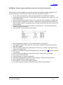
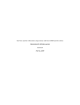
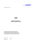
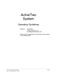
1
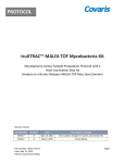
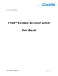
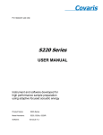
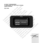
Covaris™
For research use only
Ex-series
USER MANUAL
an automated, batch system for
high performance sample preparation
using adaptive focused acoustic energy
Product Name:
Ex-series
Product Number:
E110x, E210x
Covaris™
UNIVERSAL PRECAUTIONS
Universal Precautions should be followed on all specimen samples, regardless of whether a sample is known to contain
an infectious agent. Laboratories handling specimen samples are advised to comply with applicable parts of the following
governmental and clinical standards, or their equivalent in the country of use:
•
Centers for Disease Control (CDC), Universal Precautions for Prevention of Transmission of HIV and Other
Bloodborne Infections, published 1987, updated 1996
•
Clinical and Laboratory Standards Institute (CLSI), GP17-A2 Clinical Laboratory Safety; Approved Guideline Second Edition, published 2004, ISBN 1-56238-530-5
•
Clinical and Laboratory Standards Institute (CLSI), M29-A3 Protection of Laboratory Workers from
Occupationally Acquired Infections; Approved Guideline, Third Edition, published 2005, ISBN 1-56238-5674
•
Occupational Safety and Health Administration (OSHA), 29 CFR 1910.1030 Bloodborne Pathogens
•
International Standards Organization (ISO) 15190:2003, Medical Laboratories – Requirements for Safety
Trademarks
Patented or patent pending and registered or registration-pending trademarks of Covaris are protected.
Registered names and trademarks used in this document, even when not specifically marked as such, are not to be
considered unprotected by law.
Information subject to change without notice
For Research Use Only
Not for use in diagnostic procedures
Publication P/N 010097 Rev C
April 2009
Covaris products are covered by Patent No. US 6,719,449, US 6,948,843, and other pending applications
Copyright ©2010 Covaris, all rights reserved.
Covaris, Inc.
14 Gill Street, Unit H
Woburn, Massachusetts
01801-1721 USA
Ex-series User Manual
Printed in U.S.A.
2
Covaris™
Warnings
For safety of operating personnel:
1. Make sure that the equipment is properly grounded. DO NOT operate if it is not properly grounded.
2. The unit is equipped with a power plug appropriate for the destination country. DO NOT, under any
circumstances, remove the grounding prong from the power cord.
3. DO NOT attempt to operate the equipment without the safety door closed. When the safety door is
open, the mechanical positioning system and the acoustic wave system will not run. If there is any
indication that the safety system is not functioning properly, DO NOT operate the equipment and
contact Covaris immediately.
4. If the equipment is used in a manner not specified by the manufacturer, the protection provided by
the equipment may be impaired.
To prevent damage to the equipment:
1. The instrument is designed to operate in ambient laboratory conditions e.g., 15 to 32°C (60 to
90°F). DO NOT operate the instrument in a cold room environment; the system is designed to
operate with a water bath and re-circulating heater/chiller apparatus to control sample
temperatures.
2. NEVER run a process without a water bath; this could damage the transducer. The instrument is
equipped with a water level sensor to protect the transducer. The system will not allow the acoustic
wave treatment to start unless an adequate volume of water is present.
3. ONLY distilled or deionized water should be used to fill the water bath.
4. Empty the water bath and wipe dry EVERY day. DO NOT leave water in the tank for extended time
as there is no water filtration or water cleaning system with the apparatus. Drain the degassing
lines (see section 4.5 Shutdown Procedure).
5. Establish a standard of operation and periodically test equipment, as described in the Maintenance
section of this manual.
6. Be advised that loading third party software onto the computer may interfere with the performance
of the Covaris SonoLab™ software. Please consult Covaris.
Ex-series User Manual
3
Covaris™
Warranty
When used in accordance with written instruction and under normal operating conditions, the Covaris
instruments are guaranteed to be free of defects in MATERIAL and WORKMANSHIP for one (1) year from the
date of original delivery. Any component which proves defective during the stated period will be repaired free
of charge or replaced at the sole discretion of Covaris, F.O.B., Woburn, Massachusetts, provided the defective
component is returned properly packaged with all transportation charges prepaid. The customer is expected
to perform basic diagnostics and component replacement with telephone support from Covaris personnel. If
Covaris personnel are required to perform on-site repair, all travel costs are paid by the customer. A limited
warranty as specified may apply to certain components of the equipment.
Warranty Exceptions
This warranty is void if failure of the software or hardware has resulted from accidents, abuse, improper
maintenance, or repair, or misapplication by the customer. It is also void if damage is caused by any
unauthorized attachments or if modifications are made to the equipment. Removing or tampering with the
Safety Enclosure will void the warranty, and the customer will assume all liabilities.
This warranty is limited to the original purchaser and is not transferable.
The software will perform according to the accompanying written materials and the medium on which the
software is delivered is free of defects in materials under normal use and service. The warranty is void if
damage has resulted from third party software not intended for use with the system.
The high power focused transducer is designed to give maximal mechanical energy output in water.
Permanent damage to the transducer and electronic circuits could result if the transducer is operated without
water. Operation of the system without water in the water bath voids the warranty.
CONTACT COVARIS, INC. SHOULD YOU HAVE ANY QUESTIONS CONCERNING EQUIPMENT.
Warranty Services
The purchased equipment is covered by a twelve (12) month warranty which includes all the service and
support necessary so that the customer can operate the equipment successfully. Extended warranties are
available at the end of the original 12 month warranty period.
Services included with the original purchase of the system are:
Technical Support – On-going assistance with the operation or application of the equipment and/or
troubleshooting is provided via:
•
Telephone (+1 781 932 3959) during the hours of 9:00am to 4:00pm, Monday through Friday,
o
o
•
United States, Eastern Standard Time (EST).
Greenwich Mean Time (GMT-05:00)
E-mail queries to [email protected]
Parts Replacement – Replacement of parts (excluding consumables and cables) for normal operation of
equipment are provided on a priority basis. Shipping charges are included. Failure due to accident, abuse, or
improper operation is not covered.
Ex-series User Manual
4
Covaris™
TABLE OF CONTENTS
1.0 INTRODUCTION ............................................................................................................................................ 6
1.1 Overview of the Manual ............................................................................................................................... 6
1.2 Purpose of the Equipment .......................................................................................................................... 6
1.3 Main Components ......................................................................................................................................... 7
1.4
Principle of Operation......................................................................................................................... 7
2.0
INSTALLATION.................................................................................................................................... 8
2.1 Unpacking and System Setup .................................................................................................................... 8
2.2 Placement of Equipment ............................................................................................................................. 8
2.3 Power Requirements .................................................................................................................................... 8
2.4 Set-up Procedures ........................................................................................................................................ 9
2.4.1
Powering Up the System ................................................................................................................... 9
2.4.2
Connections .......................................................................................................................................... 9
2.4.3
Control Buttons .................................................................................................................................... 9
2.4.4
Water Bath Configuration ................................................................................................................ 10
3.0
SYSTEM DESCRIPTION ................................................................................................................... 11
3.1 General Overview ........................................................................................................................................ 11
3.2 Treatment System ....................................................................................................................................... 11
3.2.1
Acoustic Transducer......................................................................................................................... 11
3.2.2
Temperature Sensors and Temperature Control ....................................................................... 11
3.2.3
Sample Positioning System ............................................................................................................ 11
3.2.4
Water Bath and Degassing System .............................................................................................. 12
3.3 Computer ....................................................................................................................................................... 12
3.4 Safety System .............................................................................................................................................. 12
3.5 Water Bath Quality ...................................................................................................................................... 13
3.6 Application Software .................................................................................................................................. 14
3.6.1
Main Panel ........................................................................................................................................... 14
3.6.2
Process Configuration Panel .......................................................................................................... 17
4.0 SYSTEM OPERATION ................................................................................................................................ 20
4.1 Start-Up Procedures ................................................................................................................................... 20
4.2 Creating and Modifying a Process in the Process Configuration Panel....................................... 21
4.3 Running a Process in the Main Panel .................................................................................................... 21
4.4 Manual Overrides ........................................................................................................................................ 22
4.5 Shut-Down Procedures.............................................................................................................................. 22
5.0 SYSTEM SPECIFICATIONS ...................................................................................................................... 22
6.0 MAINTENANCE ........................................................................................................................................... 24
6.1 Water Bath..................................................................................................................................................... 24
6.1.1
Recommendations for Daily Maintenance .................................................................................. 24
6.1.2
Recommendations for Monthly Maintenance ............................................................................. 24
6.2 Transducer .................................................................................................................................................... 24
6.3 Safety System .............................................................................................................................................. 24
6.4 Degassing the System ............................................................................................................................... 24
6.5 Relocation of the System .......................................................................................................................... 24
6.5.1
Prepare the System ................................................................................................................................ 25
6.5.2
Move of the System ............................................................................................................................... 25
6.5.3
Reinstall the System .............................................................................................................................. 25
7.0 TROUBLESHOOTING ................................................................................................................................ 26
APPENDIX A: Sample Preparation Requirements .............................................................................................. 27
APPENDIX B: Installation Procedure for Covaris Ex-Series Software and Drivers......................................... 28
Ex-series User Manual
5
Covaris™
1.0 INTRODUCTION
1.1
Overview of the Manual
This manual contains operation and maintenance instructions for the Covaris Ex-series instruments
(the E110x and E210x). It contains background information essential to the proper use and care of
this equipment.
The following definitions apply in this manual:
NOTE:
Inconvenience only if disregarded – no damage or personal injury
CAUTION:
Equipment damage may occur, but not personal injury.
WARNING:
Personal injury may occur – DO NOT DISREGARD.
There is also a PDF version of this manual on the system computer (if a computer was supplied
with your order). Open the manual by double clicking the manual icon on the desktop.
1.2
Purpose of the Equipment
The Ex Series instruments are used for high-throughput, sample preparation and extraction. The
technology uses controlled and highly focused nonlinear acoustic waves that are delivered to each
sample. The systems are designed to work with a variety of closed or open sample vessels
including vials, tubes, and multi-well plates. In general, the E110x is best for samples less than 50
mg and volumes less than 0.5 ml and the E210x is most appropriate for samples less than 500 mg
and volumes less than 5 ml. These ranges may be increased or decreased depending upon buffer
composition and sample/buffer ratios (contact Technical Support for more information).
CAUTION:
Operating the E110x or E210x instruments at power levels above 300 Watts (as
reported by SonoLAB software) for more than 5 minutes may result in damage
to the equipment. Avoid treatment parameters that result in power levels
greater than 300 Watts. If a treatment exceeds this limit, allow at least 5
minutes of zero power operation for the system to cool. Contact Covaris
Technical Support for help.
CAUTION:
Processes developed and optimized in the E110x system are not necessarily
transferable to the E210x system. Contact Covaris Technical Support for help.
The instruments are not intended for use in diagnostic procedures; for research use only.
CAUTION:
Ex-series User Manual
The system is designed to work primarily with closed sample holders. Open
vessels may be used; however, the energy should be dramatically reduced as
there is potential for leakage and spilling into the water tank. Please contact
Covaris Technical Support for guidance in this area if open vessel processing is
required.
6
Covaris™
1.3
Main Components
The main components of the E Series instruments include:
•
acoustic transducer
•
temperature sensing device
•
sample positioning system
•
degassing pump
•
water bath
•
user manual
External components include a notebook computer.
The user is expected to provide a recirculating chiller/heater. Covaris can provide specifications for
recommended recirculators.
Figure 1
1.4
Principle of Operation
The Covaris Process generates acoustic shock waves to cause controlled cavitation and acoustic
streaming at the focal point within the sample treatment vessel. Acoustic energy has been utilized
for many years for a variety of diagnostic, therapeutic and research purposes. Well-known uses of
sonic or acoustic energy in materials processing include "sonication", an uncontrolled process of
mechanical disruption involving the direct immersion of an unfocused kHz range (e.g., 15,000
cycles per second) ultrasound source into a fluid suspension of the material being treated. There
are also specific clinical examples of the utilization of therapeutic ultrasound (e.g. lithotripsy) and of
diagnostic ultrasound (e.g., fetal imaging).
Typically, when ultrasound is applied to a bulk biological sample solution (as for the extraction of
intracellular constituents from tissue), the treatment causes a complex, heterogeneous, mixture of
Ex-series User Manual
7
Covaris™
sub-events that vary during the course of a treatment dose. In other words, the ultrasonic energy
may be partitioned between various states. For example, the energy may directly treat a sample;
the energy may displace the target and shift the target out of the optimal energy zone; the energy
may result in interference, (i.e., a “bubble shield”), that reflects the acoustic energy; or the large
particles may move to low energy nodes thereby leaving the smaller particles with more dwell-time
in the high energy nodes. In addition, the sample viscosity, temperature, and uniformity will vary
during the ultrasonic process, resulting in gradients during the process. The current low frequency,
unfocused sonicator-type processes are random and non-uniform. This limits the use of ultrasound
in high throughput applications where treatment standardization is required.
In contrast, focused, nonlinear acoustic waves are computer generated and delivered to
individually-addressable samples with either of the Ex series systems: E110x and E210x. The
mechanical energy imparted on the sample results in a controlled series of compression,
rarefaction events. The Ex-series instruments were designed to provide the researcher with
methods and systems to control the delivery of mechanical energy into a biological sample for highthroughput sample preparation applications.
2.0
INSTALLATION
2.1
Unpacking and System Setup
The Covaris system is shipped in one crate, containing the instrument, the instrument supplies,
optionally purchased notebook computer, and the selected accessory kit. Remove all wrappings,
taking care not to inadvertently discard any parts, accessories, or documents.
Normal precautions in unpacking and reasonable care in handling should be exercised to avoid
possible damage to the unit. Visually inspect all external controls, indicators and surfaces to detect
any damage that may have occurred during shipment.
The shipping company is responsible for damage to equipment during shipment. If damage has
occurred, notify the shipping company immediately to establish proper basis for a claim.
NOTE:
In case of damage do not discard packing material until Covaris has inspected for
cause of damage.
WARNING:
Risk of back injury. The instrument weighs approximately 110 pounds (50
kilograms).
2.2
Placement of Equipment
The area required for the instrument (see Figure 1) is approximately 24” wide by 30” deep by 19”
high (61 cm x 76 cm x 48 cm). Space on, under or adjacent to the bench is required for a notebook
computer. Additional space may be required for a user-supplied recirculator.
Two fans maintain a safe operating temperature in the instrument by circulating air over the internal
components. Therefore, place the instrument so that there is a minimum of 1” (3cm) between the
rear panel and any wall or obstruction for airflow.
2.3
Power Requirements
The instrument draws a maximum of 500 VA. The Covaris Ex-Series instrument is configured with
a universal power supply. Refer to label on backside of instrument for specific power requirements
In case of a power interruption, the system will halt. The equipment will then need to be restarted.
As files or data not saved prior to the power interruption will be lost, the use of an UPS
(Uninterrupted Power Supply) is recommended with this system if your site has frequent power
surges or loss of power. The UPS should be capable of supplying full 5 amperes at the voltage
used.
Ex-series User Manual
8
Covaris™
WARNING:
2.4
To prevent the possibility of electrical shock, always plug the system into a
grounded power source.
Set-up Procedures
2.4.1
Powering Up the System
Power up the Covaris system by moving the power switch to the “1“ position. If the computer is
supplied by Covaris, turn it on. Open the SonoLab software by double clicking the SonoLab
icon on the desktop.
NOTE:
If user is supplying a computer, see Appendix B for instructions on loading drivers.
2.4.2
Connections
Ensure that the user-supplied chiller is connected to the CHILLER IN and OUT ports on the left
side of the instrument using the Covaris supplied hoses. The hoses are setup with quick
disconnect fitting to be attached to the instrument and hose clamps for the user supplied chiller
Ensure there is a USB cable connected from a USB port on the computer to the USB port on
the instrument (located above the power switch on the right side, near the back of the
instrument).
2.4.3
Control Buttons
There are three control buttons located on the right side
of the instrument as shown in Figure 2. The white
DEGAS PUMP button is used to degas the water bath
prior to sample treatment processes. See section 3.2.4.
The red STOP button can be depressed at any time to
halt operation. The green DOOR button, when lit, can be
depressed to allow the operator to open the safety
enclosure door (See section 3.4).
Figure 2
Ex-series User Manual
9
Covaris™
2.4.4
Water Bath Configuration
The water bath tank needs to be oriented properly when inserted into the system. The bath
should be oriented with the label “Insert this end” at the back of the tank (see Figure 3). The
"waterline" label will be displayed on the front side of the tank.
Figure 3
CAUTION: The magnetic safety interlock will not allow the instrument to operate if the water
tank is not oriented properly and fully inserted.
Fill the water bath to the water level indicated on the left side (FILL) of the water level label (see
section 3.2.4). The water level will rise when the transducer is submerged. Only distilled or
deionized water should be used to fill the water bath.
CAUTION:
Never run a process without a water bath. This will permanently damage the
transducer.
CAUTION:
Using anything besides distilled or deionized water in the water bath is a
misapplication of the equipment and will void the warranty.
The system includes a water level sensor. If the water level is too low, a warning message will
be issued by the software. In addition, the degas pump will not operate for more than 10
seconds if a low water level is detected. This is to protect the pump from running without water.
Prior to running a process, the water bath should be degassed for 1/2 hour (30 minutes).
Degas the system by lowering the transducer (click LOAD SAMPLE button on the MAIN
PANEL of SonoLab) and then depress the DEGAS PUMP button. (This is the white button on
the right side of the safety enclosure (see Figure 2)).
NOTE:
The DEGAS PUMP button will not engage the degassing pump if the transducer
is in the CHANGE BATH position
NOTE:
The degas pump will turn off after 10 seconds if the water tank is not filled with
water to the fill line.
Ex-series User Manual
10
Covaris™
NOTE:
3.0
If the degas pump switch is turned on or off while a process is running, the action
is delayed until the process has ended.
SYSTEM DESCRIPTION
3.1
General Overview
The Covaris E110x or E210x, as shown in Figure 1, is a custom instrument for high-throughput
sample preparation and compound management. The system is comprised of the Treatment
System which delivers the energy to the sample, the Safety System which provides intelligent
interruption during the “treatment”, and the Computer and the Application Software which provide
the user interface to the entire system.
This instrument is a very powerful, high-energy system. It is designed to disrupt and homogenize
biological tissue, extract biochemicals, and accelerate reagent dissolution.
3.2
Treatment System
3.2.1
Acoustic Transducer
The acoustic transducer delivers a high intensity, focused, computer-controlled acoustic shock
wave to a sample. This is called the “treatment”.
WARNING:
3.2.2
Objects at the focal point of the transducer will be exposed to high energy
when the system is activated.
Temperature Sensors and Temperature Control
The water bath sensor, a 5cm metal probe, monitors the temperature of the water bath. The
water bath temperature limits are 5º C and 40º C. The water bath temperature is controlled by
connecting an external recirculating chiller/heater to the ports in the back of the system. The
recirculator will pump a temperature-controlled fluid through a stainless steel loop immersed in
the water bath.
NOTE: Although the Ex-series instrument reports the bath temperature via the Temperature
Sensor, it does not control the recirculating chiller. Typically, for most applications (e.g., gene
expression, proteomics, compound dissolution, and drug metabolism studies) the temperature of
the recirculating chiller is set to 15 degree C with the temperature of the water bath equilibrating
at 18 degree C.
CAUTION: A recirculating chiller is required for efficient and controlled operation of the Exseries instrument.
3.2.3
Sample Positioning System
The major components of the system include:
The sample positioning system (x, y, z axes)
The transducer positioning system (z’ axis)
The sample holder plate
Figure 4 shows the sample holder plate with the A1 position identified.
Ex-series User Manual
11
Covaris™
A1 position
Figure 4
3.2.4
Water Bath and Degassing System
The water bath holds approximately 1.3 gallons (4.92 liters) of
distilled or deionized water. The water level is indicated by a
label on the front wall of the water bath. The left side of the label
(“FILL”) indicates the water level when filling the bath. The right
side of the label (“RUN”) indicates the water level when the
transducer is submerged.
The water level will be dictated by the tube rack. If Covaris has
provided an Instruction for Use (IFU) for your tube rack, please
refer to it for the recommended water level. If no water level is
specified, fill the water bath to the “0” level.
The water bath has double walls for insulation.
WARNING:
The water bath is heavy when filled. Use caution when moving it.
The degassed, temperature controlled water provides an efficient energy couplant from the
transducer to the sample to be processed. The water bath must be degassed for proper
operation of the instrument. The degassing system is engaged by depressing the DEGAS
PUMP button on the right side of the instrument when the transducer is in a lowered position.
The degassing system circulates the water past the sample vessel being processed.
The degassing system consists of a dip tube with six small holes, a positive displacement
pump, and an outlet nozzle. Dissolved gasses and vapors are reduced in the water by pulling
the water through the small holes in the dip tube and pumping the resulting coalesced bubbles
out the outlet nozzle before they can re-dissolve. During normal operation, there should be an
intermittent stream of bubbles coming from the outlet nozzle. If no bubbles are visible for
several minutes, the six small holes in the dip tube may be plugged. If this occurs, the dip tube
may be removed and the holes cleared with a fine wire (e.g., 26 Gauge needle).
3.3
Computer
The computer uses the Microsoft™ Windows® XP Professional Operating System with SonoLab™
application software.
3.4
Safety System
The safety system protects the user from hazards associated with the acoustic treatment system
and the moving parts in the sample positioning system.
The safety system prevents operation of the instrument if the door is open or the water tank is not
in place. The door can only be opened when the green light on the DOOR button is lit. Once lit,
Ex-series User Manual
12
Covaris™
pressing the button will allow the door to be opened. There is also a red STOP button on the right
of the safety enclosure (see Figure 2). Depressing the STOP button halts all operations and the
Stop Button Dialog Box comes up which allows the user to either Resume or Abort the current
operation as shown in Figure 5.
Figure 5
NOTE: The door may be opened in the event of a power failure by inserting a special tool
provided with the instrument into the hole in the enclosure above the safety interlock and
rotating clockwise 90 degrees. The instrument will not operate if the safety interlock is
disabled. The tool is stored in a clip on the back of the instrument.
3.5
Water Bath Quality
The SonoLab Software can detect problems with the water bath that may impede the delivery of
acoustic energy to the sample vessel. This feature is valid only for high power applications using
round-bottom glass tubes such as 16 x 100 mm culture tubes. Water Quality Monitoring is turned
off by default. It may be activated in the process configuration panel. If water quality monitoring is
active and there is a problem with the water bath, the dialog box in Figure 6 will appear during the
process. (See section 3.6.2).
Figure 6
Ex-series User Manual
13
Covaris™
Resolve the problem and run the process again. The software also monitors water bath
temperature. If the bath temperature is higher than a user defined limit, while a process is running,
the process is halted and the following dialog box will appear.
Figure 7
3.6
Application Software
3.6.1
Main Panel
Software Panel 1: MAIN PANEL
Ex-series User Manual
14
Covaris™
Motion Buttons
The motion buttons move the sample holder and the transducer. They operate as follows:
LOAD SAMPLE raises the sample holder out of the water bath
CHECK ALIGNMENT moves the sample holder plate to position A1
CHANGE BATH raises the transducer and sample holder out of the water bath
General Process Buttons
OPEN button loads an existing process configuration from a saved file.
CONFIGURE button will take the operator to the Process Configuration Panel which allows the
user to create and/or modify a process.
START button starts running a process. After selecting the button, a warning dialog box opens
to ensure the system is ready to proceed. The warning reminds the user to check that there is
water in the water bath, that the system has been degassed, and that there are samples in the
sample holder. See the warning screen below:
Figure 8
If the user is ready to proceed, click the START button.
STOP halts the operation of the sample positioning system.
NOTE: The STOP button on the instrument and the STOP button on the display perform the
same function.
The EXIT button will exit the program.
The Status Indicator Lights
PROCESS RUNNING indicates the process has been started has not been stopped or paused
and has not yet completed.
MOTORS MOVING indicate the positioning system is moving in any axis.
DWELL indicates when the stage is at the center of the well in between dithering functions.
STOP BUTTON indicates when STOP button is pressed.
Ex-series User Manual
15
Covaris™
SAFETY INTERRUPT indicates the software senses that the mechanical safety interlock is in
the open position.
DEGAS indicates the degassing pump in engaged.
While a process is running, the following indicators display current treatment parameters:
BATH displays the temperature of the water bath.
CURRENT TREATMENT displays the parameters DUTY CYCLE, INTENSITY, and
CYCLES/BURST defined for the current well being processed. (Refer to section 3.6.2)
ACOUSTIC POWER GRAPH shows the acoustic power being delivered to the sample for
each treatment.
Pie Chart Well Graph
Each well position is represented as a pie chart. The pie charts fill in to indicate the progress of
the treatment in each well. A well undergoing treatment is red and once completed the color
changes to blue.
Progress Bar
Indicates the percent completed of the currently running process (as a percent of the total
calculated time).
Pull-down Menus
Help:
SHOW/HIDE HELP opens a help dialog box when the cursor passes over the
button controls. A brief description is in the box.
Ex-series User Manual
16
Covaris™
3.6.2
Process Configuration Panel
Software Panel 2: PROCESS CONFIGURATION PANEL
This screen allows the user to select both a previously created process (and its associated
parameters) or to create a new process. On the left side of the screen are the controls to setup the well plate.
The SEQUENCE menu has a list of pre-defined sequences (the order of the samples being
processed during a run) or the option none to allow the user to create their own sequence.
The CLICK ACTION menu uses the replace option to replace the last selected well position
sequence with the newly selected well position. The append option allows the user to add the
newly selected well position to the end of the list of well parameters.
The WELL PLATE menu pulls up a list of pre-defined treatment vessel configurations (multiwell plate). The diagram below it, WELL PLATE, displays the well configuration of the selected
plate.
The APPLY SEQUENCE button creates a process by applying the treatment settings in the
upper right panel to all the wells of the well plate definition using the ordering of the selected
sequence (top left).
Ex-series User Manual
17
Covaris™
The PROPAGATE button creates multiple sequences per well by applying the treatments
highlighted in two or more rows in the table (lower right) using the ordering of the selected
sequence (top left).
Current Well Parameters
For a new or an existing process, the user may define and edit the individual well parameters or
sequence in the control panel. Each sequence number correlates to a number in the WELL
PLATE graphic (lower left). For multiple sequences in a WELL, the last sequence number
displays. Clicking on a well in the graphic, adds the well to the sequence.
WELL is the current treatment position in the well plate. The set of parameters defined for
the well is a treatment. When WELL is checked, multiple treatments to the same well can
be achieved by selecting PASTE VALUES. The WELL number in the table goes blank
indicating that the defined treatment is in the same well. When WELL is unchecked,
selecting PASTE VALUES does not change the well number indicating that the treatment is
the displayed well.
TREATMENT TIME is the amount of time (sec) to apply the parameters or to treat a
well sample.
Acoustic energy is produced in bursts and the Ex-series system allows the user to modify this
energy to maximize the effects on the treatment samples for any particular application. Contact
Covaris Technical Support for recommendations regarding these settings.
DUTY CYCLE is defined as a percentage. For example, within a timeframe it is the
percentage of the time that the transducer is creating acoustic waves; the “on” cycle.
Typically, the higher the DC the higher the acoustic waves per unit time is generated by the
transducer. Minimum is 1% and Maximum is 50%.
INTENSITY: The amplitude of the pressure waves created by the acoustic transducer.
The larger the number, the more energy each acoustic wave has. Minimum is 0.1 and
maximum is 10.
CYCLES PER BURST: The number of waves generated by the transducer in a burst. For
example, 100cpb at 10% duty cycle is a wavetrain of 100 “on” energy cycles followed by
900 “off” energy cycles. Minimum is 50 and Maximum is 1,000.
Dithering is the controlled horizontal circular movement of the treatment vessel around a center
point during processing to mix the sample. For horizontal dithering, the following parameters
can be set:
RADIUS is the radius (in mm) the vessel moves in a circular motion.
RATE is the speed (in rpm) of this movement of the vessel.
DWELL is the time the vessel remains at the center point between dithering operations.
To move the data to/from the current well to the control panel, use the following buttons:
COPY button copies or adds the parameter information (treatment) defined in a well to the
control panel. To copy, highlight a row in the table, and select COPY.
PASTE VALUES copies the parameter information (treatment) defined in the control panel
to a highlighted row(s)
DUPLICATE SELECTION allows the user to define multiple treatments to an individual well.
Process Wide Parameters Box
The Monitoring Water Bath Quality button is used to detect any problems that could cause the
water bath not to properly conduct the acoustic energy such as contamination, high
temperature, or insufficient degassing.
Ex-series User Manual
18
Covaris™
The Frequency Tuning Menu has three modes:
1. FREQUENCY SWEEPING: The acoustic frequency sweeps through a range during
processing. This is the default setting for the E-series instruments. As plastic readily
absorbs acoustic energy, this lower power setting is more appropriate for process
development with plastic vessels. Frequency sweeping is both preferred and
recommended for plastic sample vessels.
2. POWER TRACKING: In this mode, the instrument optimizes the operating frequency
to achieve peak power in the treatment vessel for the treatment chosen. This mode
delivers the most effective power and the highest level of mixing to the sample. It is also
the best for most applications, especially biologically active samples (e.g., RNA extraction
from tumor tissues samples or proteomic preparation) where rapid sample processing is
required. This setting may also be appropriate for chemical-based samples (e.g., small
molecule drug extraction from slow release tablets, compound dissolution, or metabolite
extraction from plant tissue). Power Tracking is both preferred and recommended for highpower treatments in glass sample vessels.
CAUTION: When used with some high power treatments and some vessels (e.g., plastic)
Power Tracking Mode may result in heating of the sample (e.g., viscous, fibrous samples).
3. VERTICAL SWEEP moves the sample up/down during processing. The menu is active
when Vertical Sweep is selected.
VERTICAL +/- is the vertical movement in mm.
VERTICAL RATE is the frequency in cpm (cycles per minute).
NOTE:
The ability to monitor water bath quality is not active in this mode.
BATH TEMPERATURE LIMIT allows the user to select a temperature limit for the treatment.
The overall operating limits of the water bath temperature are 5º C and 40º C. If the water
temperature is over the specified limit, the BATH thermometer on the front panel will flash
yellow and processing will be halted. It can be restarted by selecting OVERRIDE in the
temperature warning dialog box.
General Operation Buttons
NEW PROCESS button allows the user to enter a new set-up for a process. A dialog box pops
up to ask for a name.
OPEN allows the user to select a process from the list of previously created processes.
SAVE allows the user to save a process set-up as a *. pcx file.
RETURN exits the screen to return to MAIN Panel
Pull-Down Menus
File:
NEW PROCESS (Ctrl+N) creates a new configuration process.
OPEN PROCESS (Ctrl+O) allows opening a currently saved process
SAVE PROCESS (Ctrl+S) allows a new or opened process to be saved.
EXIT PROCESS (Ctrl+Q) exits the Process Configuration Panel.
Edit:
Ex-series User Manual
Typical editing functions available for a currently opened process and its list of well
parameters
19
Covaris™
CUT (Ctrl+ X) cut or delete selection, which can be used to paste elsewhere
COPY (Ctrl+C) copy selection
PASTE (replace) (Ctrl+V) replaces selection with last COPY
INSERT AFTER inserts the copied parameters after the sequence selected
UNDO (Ctrl+Z) undo last action
REDO (Ctrl+Y) repeats the last action.
SELECT ALL (Ctrl+A) selects all lines
DELETE SELECTION deletes selected line(s)
Help:
4.0
SHOW/HIDE HELP opens a help dialog box when the cursor passes over the
button controls. A brief description is in the box.
SYSTEM OPERATION
4.1
Start-Up Procedures
Chiller Connection
The recirculating chiller (required) should be connected to the treatment system using the hoses
supplied. The chiller inlet is connected to the fitting labeled “IN” and the chiller outlet is connected to
the fitting labeled “OUT” located on the left side of the instrument.
Water Bath
The water bath level needs to be checked periodically using the water level label on the tank. With
the samples at the treatment position, the water level should be within +/-3mm of the appropriate
waterline on the RUN side of the water level label (see section 3.2.4). Only distilled or deionized
water is used in the water tank.
Special care needs to be taken when changing the water bath. First, select the CHANGE BATH
button to raise the transducer. Then carefully pull out the acrylic water tank from the instrument
base plate and empty it. Fill the water tank and place it back into its position, ensuring that it is
oriented properly in the instrument (see section 2.4.4).
WARNING:
The water bath is heavy when filled. Use caution when moving it.
CAUTION:
Never run a process without a water bath; this will permanently damage the
transducer.
CAUTION:
Do not run processes with sustained power levels above 300 Watts, as this may
cause permanent damage to the equipment.
Degassing
The Covaris system requires that the water bath be degassed to maintain repeatable acoustic
energy coupling, therefore, the pump should be running whenever samples are being treated. This
is especially critical for high intensity applications such as solid tissue homogenization. At room
temperature, the water bath should be degassed for at least 1/2 hour prior to running a treatment
process. Depress the DEGAS PUMP button. Ensure the water bath is filled to the water level
before turning on the pump; otherwise, damage to the pump may occur.
Ex-series User Manual
20
Covaris™
NOTE:
The degassing pump will turn off after 10 seconds if the water tank is not filled
with water.
Loading the Multi – Well Plate Holder
Select the LOAD SAMPLE button on the Main Panel to raise the multi-well plate holder. The
system will position the stage above the water bath.
Fill the multi-well plate with the sample vessels to be run. Place the hold-down plate over the
vessels. The hold-down plate ensures that the vessels stay in place for correct processing.
The plate should be loaded on the multi-well plate holder with the A-1 position in the upper right
corner. See Figure 4.
NOTE:
4.2
Ensure the well-plate is seated flush onto the well-plate holder to insure the
samples are correctly aligned with the focal point of the transducer.
Creating and Modifying a Process in the Process Configuration Panel
To open an existing process to run or to modify, select OPEN PROCESS and choose from the list
of previously saved set-ups.
To create a new process, select the NEW PROCESS button.
Select the Well Plate Configuration from the WELL PLATE menu.
Select a Sequence from the list in the SEQUENCE menu. Selecting NONE here will allow the user
to customize a sequence. This is done by selecting individual wells in the well plate configuration.
If some of the positions on the plate are empty, the process can be reconfigured to delete the
empty positions from the process (see section 3.6.2).
Parameters may now be selected in the Process Wide Parameter box.
Select the Current Well Parameters
For each sequence number or well, a treatment can be configured using the controls at the top of
the screen. See Section 3.6.2.
Save the set-up by selecting the SAVE button. The system will prompt the user to name the setup.
4.3
Running a Process in the Main Panel
Load the samples first by selecting the LOAD SAMPLE button. The motion system will move the
sample holder tray to the front of the enclosure and the green DOOR button will illuminate. Press
the DOOR button to open the door and position the samples on the tray.
Click the OPEN PROCESS button. Select from the list of defined processes.
Move the samples to the treatment position by selecting the CHECK ALIGNMENT button. Check
the water level is at the appropriate level on the RUN side of the label.
Click the START button.
CAUTION:
Ex-series User Manual
If the computer loses connection with the instrument during processing, the
process will stop.
21
Covaris™
4.4
Manual Overrides
There is a STOP Button on the Computer screen. This will halt the current process. The process
may also be stopped by pressing the red STOP button on the instrument. The green DOOR button
will light once the process has stopped.
To restart, the system will prompt the user with a message to either RESUME or ABORT the
process. If the door is not closed, selecting RESUME will prompt the user again to RESUME or
ABORT. Selecting RESUME with the safety system closed will continue the process where it was
interrupted. Selecting ABORT terminates the process.
4.5
Shut-Down Procedures
Raise the transducer out of the water bath by selecting the CHANGE BATH button. Sponge out the
“bowl” of the transducer to remove water. Empty the water bath. If the instrument will be idle for an
extended time, run the degassing pump with an empty water bath for 10 seconds to drain the
degassing lines. The transducer must be lowered to run the pump.
CAUTION:
Leaving water in the water bath or degassing lines can cause algae growth in the
tank and lines which may interfere with sample processing.
Exit the SonoLab software by selecting EXIT on the main panel.
Select Shutdown from the START menu on the Windows XP screen and select the option “Shut
down the computer”. The computer will power down. The instrument can be powered down by
moving the power switch to the “0” position. The power switch is located at the rear of the
instrument on the right side.
CAUTION:
5.0
Failure to raise the transducer from the water bath when not in use may result
in permanent damage to the system.
SYSTEM SPECIFICATIONS
Model
Ex Series
Treatment System
Bench-top: high intensity acoustic transducer, sample positioning
system, temperature monitoring device, circulation pump, and water
bath with safety enclosure.
Dimensions:
24” W x 30” D x 19” H
(61cm x 76cm x 48cm)
Weight:
approximately 110 lbs (50 Kg)
Ambient Temp. Range:
15 to 32°C
Power Requirements
100-120, 200-240 V~ 50-60Hz, 500 VAC
Regulatory Labeling:
CE and ETL Mark
Safety:
Meets Low Voltage Directive 2006/95/EC.
Tested to EN/UL/CSA 61010-1:2004 “Safety Requirements for
Electrical Equipment for Measurement, Control and Laboratory Use,
Part 1: General Requirements”
EMC:
Meets EMC Directive 2004/108/EC. Tested to EMI emissions
requirements for Industrial Scientific or Medical (ISM) equipment
EN55011:1998 + A2:2002 Class A Group1 and EMC requirements -
Ex-series User Manual
22
Covaris™
Electrical Equipment for Measurement, Control, and Laboratory Use
EN 61326-1:2005 Table 2, EN 61000-3-2:2004 and EN 61000-33:1995 +A1:2001.
Water Bath:
Water Temp. Alarm Limit:
Distilled or deionized water only
Can be set at +5.0°C to +40.0°C
Computer
Notebook computer (may be supplied by Covaris or the user)
Operating System
Microsoft Windows XP Professional 2002, SP3
Application Software
Covaris SonoLab
Data Input
Keyboard, mouse
Chiller
Chiller/heater re-circulating system - not included. Connect with the
3/8 inch I.D. hoses and quick connect fittings supplied
Ex-series User Manual
23
Covaris™
6.0
MAINTENANCE
6.1
Water Bath
6.1.1
Recommendations for Daily Maintenance
Only distilled or deionized water should be used to fill the water bath. The water bath should be
emptied every day to avoid algae growth. Do not use an algaecide.
The water level is dependent upon the sample vessel type. There is a water level indicator on
the tank to help determine the depth required. Refer to the Instructions For Use, IFU, supplied
with the tube rack to determine water depth. If no IFU is supplied or no water level is specified,
fill the water bath to the “0” level.
6.1.2
Recommendations for Monthly Maintenance
Periodically, the water bath and degassing lines may be rinsed with a 10% solution of Clorox
bleach. The resultant sodium hypochlorite solution is ~ 0.5% NaOCl. With this solution in the
water bath, lower the transducer and run the degassing pump for a few minutes. Repeat with
fresh water in the water bath.
6.2
Transducer
When not in use, the transducer should be raised out of the water bath and the transducer “bowl”
should be sponged out with a soft lint-free cloth or sponge to remove any residual water. Keeping
the transducer dry between applications will help prevent corrosion and is strongly encouraged to
ensure optimal performance.
Use extreme care when handling the transducer. Permanent damage could result if anything is
dropped onto the face of the transducer or if the face of the transducer strikes something.
Permanent damage could also result if the transducer is overheated, (i.e. running the transducer
without a water bath).
WARNING:
6.3
Do not attempt to remove the transducer as irreparable damage may occur.
Safety System
Test the system periodically. Make sure that the operation is halted when the STOP button is
depressed.
WARNING:
6.4
Any failure of the Safety System must be reported immediately to Covaris.
DO NOT attempt operation if the Safety System is malfunctioning.
Degassing the System
The degassing pump will shut down after 10 seconds without a water bath because running the
pump without water will damage the pump.
Check that there are bubbles coming from the end of the degassing tube. Remove the dip tube
(inlet tube) if necessary and examine it under a microscope to clear any clogged holes.
For long-term storage, all water should be removed from the degassing pump lines. This can be
done by running the degassing pump for 5 to 10 seconds with an empty water bath.
6.5
Relocation of the System
Should it be necessary to move the instrument, for whatever reason, the system needs to be
properly prepared. This procedure describes the steps necessary to relocate Covaris Ex-Series
instrument. If the instrument is to be moved off site, a crate may be obtained from Covaris.
Ex-series User Manual
24
Covaris™
6.5.1
Prepare the System
•
Raise the transducer (“Change Bath” position) and sponge out the bowl of the
transducer. Empty the water tank and reinstall it in the instrument
•
Lower the transducer and run the degas pump. Run the pump for 10 seconds, enough
to drain the water from the pump lines.
•
Raise the transducer (“Change Bath” position) and empty the residual water from the
tank
•
Leave the transducer in the up position (“Change Bath” position).
•
Save the current process and close SonoLab software by selecting EXIT on the main
panel.
•
Shut down the computer from the START menu.
•
Power down the instrument by moving the power switch to the “0” position. The power
switch is located at the rear of the instrument on the right side.
•
Disconnect the instrument power cable, the USB cable, the mouse and the computer
power supply. Gather these items and keep with the instrument.
•
Disconnect the Chiller from the instrument. Drain the water in the chiller into a bucket
through the drain fitting. The hoses can be drained by depressing the valve in the
center of each quick-connect fitting and holding over a bucket.
•
Protect the chiller quick-connect fittings on the lower left side of the instrument from
damage by taping foam or bubble wrap over them.
6.5.2
Move of the System
•
If the instrument is to be moved off-site, procure a crate from Covaris. Pack the
instrument in the crate using the provided foam inserts.
•
Protect the system and computer with a light cloth or plastic to prevent dust
contamination.
•
Be sure all the components are accounted for, including tube holders and user manual.
•
Transport the instrument and accessories. At least two capable people are required
to lift and place the instrument. The instrument weighs approximately 88lb (40kg) .
The chiller is also heavy.
6.5.3
•
Reinstall the System
Instructions for reinstalling the instrument are contained in Section 2 of the User
Manual. If the manual is missing, obtain a new copy from Covaris.
Ex-series User Manual
25
Covaris™
7.0
TROUBLESHOOTING
System Trouble Analysis Chart
SYMPTOM
PROBABLE
CAUSE
Degassing system
not generating
bubbles.
1. Degassing dip tube may be
clogged
2. Pump not working
Incorrect positioning
Home position lost
Safety interrupt
1.
2.
3.
4.
1.
Sample vessel hits
the water jet nozzle
Water tank is misaligned
Door is open.
STOP button is depressed
Safety interlock is bypassed
System has lost the home
position.
2. Incorrect nozzle position
POSSIBLE SOLUTION
1. Remove and backflush
under running water
2. Examine the six holes
(e.g., using a stereo
microscope) to see if
clogged and use a pin to
unclog them
3. If pump does not run,
contact Covaris.
Home system by pressing
selecting “initialize system
from the pull-down menu on
the main panel.
1. Check tank alignment
2. Check door
3. Check safety interlock
1. Home the system
2. Reposition water jet
manually
Error message that
system not shut
down correctly
SHUT Down command in
Windows XP not used before
rebooting
1. Follow instructions on
screen
2. Use SHUT DOWN
command
Delay in powering
degassing pump
on/off
If a process is running, there is
a delay in powering the
degassing pump on/off
Wait until process completes
before powering the
degassing pump on/off
Values for Dithering
and Vertical Sweep
are different from
the values that were
entered
Values entered are larger than
the limits for a particular Well
Plate
Use lower values
Ex-series User Manual
26
Covaris™
APPENDIX A: Sample Preparation Requirements
Although sample preparation requirements are diverse, for most samples the following ranges
apply:
Model E110 -
volume
mass
tube
100 – 1,000 µl
< 100 mg
13 x 100 mm
Model E210 -
volume
mass
tube
1,000 – 10,000 µl
< 1,000 mg
16 x 100 mm
The system may also be configured for other tubes and vials, temperatures, and robotic systems.
Please contact Covaris for any additional questions or comments regarding sample processing.
Ex-series User Manual
27
Covaris™
APPENDIX B: Installation Procedure for Covaris Ex-Series Software and Drivers
This procedure is for the installation of Covaris SonoLab Ex-Series application and supporting National
Instruments software and drivers for the operation of the Ex-Series instruments (E110x and E210x). Please
follow these instructions in sequence.
1. Install the National Instruments software and drivers
a. Create a folder on the C drive named “NI”
b. From the E-DRIVERS CD, copy the Nidaq693 setup program into the NI folder and run it.
c. From the E-DRIVERS CD, copy the LV61Eng setup program into the NI folder and run it.
d. Run Setup.exe in the NI folder on the C drive.
i. Select LabVIEW 6.1 support.
ii. Select NEXT.
iii. Reboot when prompted.
e. From the E-DRIVERS CD, launch NI-VISA (NI-VISA\NIvisa26) by scrolling down, and
follow the instructions. Use the (default) complete installation.
f. From the E-DRIVERS CD, launch VisaProvider (VISAProvider\VISA_Provider) and follow
the instructions.
g. From the E-DRIVERS CD, launch VisaServer (VisaServer\NIVISA-Server) and follow the
instructions. Select the (default) “Modify” option.
h. From the E-DRIVERS CD, launch IVI engine driver (IVIEngine\IVIEngineSetup) and follow
the instructions.
i. From the E-DRIVERS CD, launch LVRunTimeEng (LVRunTimeEng).
2. Plug in USB cable to instrument and computer.
3. Turn on instrument.
4. Follow “New hardware found” wizard. It runs four times.
a. The message comes up, “Can Windows connect to Windows Update to search for
software?” Select “No, not at this time.”
b. Select “Install automatically”.
c. Ignore the warning from Microsoft about unapproved drivers (continue anyway).
5. Update Measurement and Automation Explorer (MAX) (Desktop Icon)
a. Click View then Refresh
b. Look under “devices and interfaces”-“ports”. Note the name of the last COM port in the list.
(You will need this number for a future step.) Exit MAX.
6. On the E-DRIVERS CD, go to the GALIL directory and run the setup program
(GALIL\dmcsmartterm02.exe).
a. Select NEXT. Ignore the customer information screen by selecting NEXT. Select NEXT
again to install using the default file structure.
b. Select INSTALL. Reboot when prompted.
7. From the START menu, run the program: GALILÎ DMC Smart Terminal.
a. From the menu, select ToolsÎController Registration.
b. A dialog box appears. Select NEW CONTROLLER.
c. Enter the model. Scroll to DMC-21x3/2. Use the other defaults and select NEXT.
d. Enter the COM port number from step 5. Enter the COM speed of 9600. Do not change
Handshake options. Select FINISH. Select OK.
e. Close dialog box. Close program.
8. Remove the E-DRIVERS CD and load the SonoLab Software CD ver. 4.3.x.
Ex-series User Manual
28
Covaris™
9. Install the Covaris SonoLab software.
a. Create a folder C:\Covaris.
b. From the SonoLab Software-CD, select SonoLAB vX.X.X folder.
c. Copy and Paste into C:\Covaris Folder.
d. In the Covaris Folder, double click in the Software folder.
e. Right click the software application and Send to Desktop
10.
Confirm the software is functioning.
NOTE: Laptop standby and hibernate modes should be avoided while operating the
SonoLAB software. To ensure this, from the start menu, open Control Panel, then
Power Options. Select a Power Scheme that sets System standby and System
hibernate times to Never. If standby and hibernate modes remain enabled, then the
SonoLAB software should be closed and the system powered down whenever the
system is not in use.
NOTE: SonoLab Ex software was not tested with other application software and
therefore we recommend that no additional application software is loaded. Wireless
Network Connections on the Laptop should be disabled to avoid loading of any
unwanted software. Go to Network Connections in the Control Panel. Highlight the
Wireless Network Connection and select “disable this network device”.
Ex-series User Manual
29
Covaris™
APPENDIX C: Software Upgrade Installation Procedure for Covaris E-Series Software
This procedure is for the installation of Covaris SonoLab E-Series application software upgrade for the ESeries instruments (E-110x and E-210x). Please follow these instructions in sequence.
1. Turn on the E-series instrument computer and navigate to the Covaris software C:\Covaris
2. Create a folder titled “Covaris_Old”. Copy the folder “Covaris” and paste it into “Covaris_Old”. This
is the software backup.
3. Delete the desktop shortcut titled “SonoLab v4.x.x” and the file “Ex-series MANUAL 4.x.xREVx.pdf”.
4. Open the original Covaris folder at C:\Covaris. Inside there is another folder titled “SonoLab v4.x.x”
which contains the software, configuration files, processes, and well plate definitions needed for the
E-series operation.
5. Rename this folder to the new version of software, “SonoLab v4.3.x”. This folder name may also
contain the system serial number.
6. Open the folder. It will contain the structure below:
7. Delete the folder titled “Software”. Do not change or delete the other folders.
8. Load upgraded Software CD E-series v4.3.x into CD drive. Open the CD directory and copy the
folder titled “Software”.
9. Paste this “Software” folder into the folder titled “SonoLab v4.3.x”, to create a new Software folder
in place of the deleted folder.
10. Open the new “Software” folder and find the application file with the C Icon.
. Create a shortcut
for the desktop.
11. Copy the file “Ex-series MANUALrevXX.pdf” from the CD. Paste the file on the desktop.
12. Turn on the Ex-series instrument.
13. Using the desktop icon, launch the application.
14. Verify that the instrument and computer are communicating. Perform the homing sequence.
15. Click on OPEN PROCESS. Select any process.
16. Run the process. It will verify the system’s operation.
17. If the instrument does not perform as expected, please contact Technical Support.
Ex-series User Manual
30