1
SIDDOS-mini DYNAMOGRAPH
CONTENT
1. GENERAL INFORMATION OF THE TOOL ...... ...... ............. ...... ...... ...... ...... ...... ...... ...... ...... ......2
2. BASIC SPECIFICATIONS ...... ...... ...... ...... ............ ...... ............. ...... ...... ...... ...... ...... ...... ...... ...... ......2
3. COMPONENTS AND DELIVERY SET .. ............ ...... ............. ...... ...... ...... ...... ...... ...... ...... ...... ......3
4. SAFE OPERATION INSTRUCTIONS ... ............ ...... ............. ...... ...... ...... ...... ...... ...... ...... ...... ......4
4.1. General Provisions (Normative Base)..... ...... ............. ...... ...... ...... ...... ...... ...... ...... ...... ......4
4.2. Personnel Requirements ..... ...... ...... ............ ...... ............. ...... ...... ...... ...... ...... ...... ...... ...... ......4
4.3. Requirements to the Research Object ... ...... ............. ...... ...... ...... ...... ...... ...... ...... ...... ......5
4.4. Equipment Assemble and Disassembly Procedure ..... ...... ...... ...... ...... ...... ...... ...... ......5
4.4.1. Preparing the Research Object ... ...... ............. ...... ...... ...... ...... ...... ...... ...... ...... ......5
4.4.2. Mounting the Tool ...... ...... ...... ............ ...... ............. ...... ...... ...... ...... ...... ...... ...... ...... ......6
Attach the remote control antenna to the Dynamograph ...... ...... ...... ...... ......6
4.4.3. Unmounting the Tool ...... ...... ............ ...... ............. ...... ...... ...... ...... ...... ...... ...... ...... ......6
5. COMPONENTS AND OPERATION OF THE TOOL ....... ...... ...... ...... ...... ...... ...... ...... ...... ......6
5.1. General Information . ...... ...... ...... ...... ............ ...... ............. ...... ...... ...... ...... ...... ...... ...... ...... ......6
5.2. Arrangement, Application and Operation of the Tool ..... ...... ...... ...... ...... ...... ...... ......7
5.2.1. SIDDOSmini Dynamograph .......... ...... ............. ...... ...... ...... ...... ...... ...... ...... ...... ......7
5.2.2. Accessories ... ...... ...... ...... ...... ............ ...... ............. ...... ...... ...... ...... ...... ...... ...... ...... ......7
5.3. Tool Operation ..... ...... ...... ...... ...... ...... ............ ...... ............. ...... ...... ...... ...... ...... ...... ...... ...... ......8
5.3.1. Operating Principle . ...... ...... ............ ...... ............. ...... ...... ...... ...... ...... ...... ...... ...... ......8
5.3.2. Controls and Indicators ...... ............ ...... ............. ...... ...... ...... ...... ...... ...... ...... ...... ......9
5.3.3. Basic Functions of the Keyboard ...... ............. ...... ...... ...... ...... ...... ...... ...... ...... ......10
5.3.4. Tool Operating Modes ... ...... ............ ...... ............. ...... ...... ...... ...... ...... ...... ...... ...... ......11
5.3.5. Switching the Tool On and Off. SelfTest.. ...... ...... ...... ...... ...... ...... ...... ...... ......15
5.4. Storage and Transportation of the Tool ...... ............. ...... ...... ...... ...... ...... ...... ...... ...... ......17
6. PREPARING FOR SURVEY..... ...... ...... ...... ............ ...... ............. ...... ...... ...... ...... ...... ...... ...... ...... ......17
6.1. Preparing the tool for Operation .. ............ ...... ............. ...... ...... ...... ...... ...... ...... ...... ...... ......17
7. PERFORMING A SURVEY ...... ...... ...... ...... ............ ...... ............. ...... ...... ...... ...... ...... ...... ...... ...... ......18
7.1. Accelerometer Mode Measurement ......... ...... ............. ...... ...... ...... ...... ...... ...... ...... ...... ......18
7.2. Simulation Mode Measurement .... ............ ...... ............. ...... ...... ...... ...... ...... ...... ...... ...... ......20
APPENDIXES ...... .. .... ...... ...... ...... ...... ...... ...... ...... ............ ...... ............. ...... ...... ...... ...... ...... ...... ...... ...... ......23
APPENDIX 1. Battery Charge .... ...... ...... ............ ...... ............. ...... ...... ...... ...... ...... ...... ...... ...... ......23
APPENDIX 2. Capacity Control and Battery Cycling .... ...... ...... ...... ...... ...... ...... ...... ...... ......24
APPENDIX 3. Transferring Data to a PC.......... ...... ............. ...... ...... ...... ...... ...... ...... ...... ...... ......25
APPENDIX 4. Operation with BVK.. ...... ............ ...... ............. ...... ...... ...... ...... ...... ...... ...... ...... ......25
APPENDIX 5. Time and Date Setup. Memory Initialization . ...... ...... ...... ...... ...... ...... ......26
SIDDOS-mini DYNAMOGRAPH
1. GENERAL INFORMATION ON THE TOOL
The SIDDOSmini dynamograph (hereinafter “dynamograph”) is designed for prompt
monitoring of the performance of a sucker rod pump. The device provide dynamogram test by
the “load rod position” indirect method when the SRP is in working conditions or the well is
start up. All the measurements are made in semiautomatic mode can be performed by a single
operator.
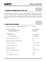
2. BASIC SPECIFICATIONS
02
1. Calibrated load for the 1 in diameter polished rod
22 046 lb
2. Operating load range
for the polished rod diameter
for the stroke length
0…up to 44 092 lb
_
(0.8 : 1.53) in
_:
(20 295) in
3. Pump speed
simulation mode
accelerometer mode
_
(0.64 : 15) SPM
_:
(3 15) SPM
4. Resolution of load monitoring
44 lb
5. Records stored in nonvolatile memory
340
6. RC operating range
no less than 20 ft
7. Continuous operation time
no less than 12 hrs
8. Battery charging time
10 hrs
9. Operating temperature range
(40 F +122 F) °С
10. Service life
5 years
11. Tool weight, not more than
3.3 lb
SIDDOS-mini DYNAMOGRAPH
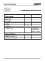
3. COMPONENTS AND DELIVERY SET
03
SIDDOS-mini DYNAMOGRAPH
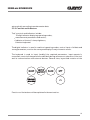
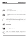
4. SAFE OPERATION INSTRUCTIONS
4.1. General Provisions (Normative Base)
1. The construction of the wellhead equipment should correspond to the scheme
approved by the State municipal engineering supervision bodies1.
2. Preparation of a well for researches and carrying out of the researches should be
performed in accordance with the requirements of the Instruction and internal well
servicing and researches instructions approved by the head of the enterprise.
3. Research equipment should be operated according to the operational instruction
delivered with the equipment by the manufacturing company.
4. Safety measures are regulated by instructions of labor protection for appropriate
types of work, approved by the labor protection department of the enterprise and by
“Safety regulations for the oil and gas industry” approved by the State municipal
engineering supervision body of Russia1.
5. Make sure that the minimum distance (“dead zone”) between the lower clamp and the
gland cap is at least 5 inch in the bottom end of stroke of the polished rod. This is
required for mounting the tool. In case this distance is less than 5 inch, it is not
allowed to mount the tool.
4.2. Personnel Requirements
1. Only people who are 18 years and older, who have a secondary or higher education
and are in health conditions allowing them to work in this area are permitted to carry
out well researches.
2. The personnel should be professionally trained, examined and have a special
permission to conduct the works according to the job specifications.
3. The personnel should be trained to operate on the research equipment. The training is
performed by employees of the manufacturing company directly on the work place.
04
SIDDOS-mini DYNAMOGRAPH
4.3. Requirements to the Research Object
1. Pumping units any type and any construction (if allowable to use with the tool).
2. Sucker rod any length and configuration, if ends with a 0.8...1.53 in diameter
polished rod.
3. Sucker rod pumping units of all standard sizes may be used.
4. Sucker rod pumping unit and its electric system should be installed and maintained
according to the Safety Regulations for Oil and Gas Industry.
5. Pumping unit control station should have a capability of switching into manual
operation mode.
6. Moving parts of the pumping unit (crank drive, vbelt transmission) should be
protected by the standard fencing.
7. Gearbox of the pumping unit should be equipped with a functional hand brake.
4.4. Equipment Assemble and Disassembly Procedure
4.4.1. Preparing the Research Object
Stop and lock in the bottom position of the bridle.
Make sure that the minimum distance (“dead zone”) between the lower clamp and the
gland cap is at least 5 inch in the bottom end of stroke of the polished rod. This is required
for mounting the tool. In case this distance is less than 5 inch, it is not allowed to mount the
tool.
Scrape the polished rod where the tool is to be mounted until clean metal shows.
05
SIDDOS-mini DYNAMOGRAPH
4.4.2. Mounting the Tool
Attach the remote control antenna to the tool.
Put the tool where it will be mounted, parallel to the clamp plane and axis, pushing the
jacks next to the polished rod.
Switch on the tool in the current load monitoring mode (see Section 5.3.4). Gradually,
without applying excessive force, tighten the main screw by rotating it clockwise while the
«SCR» (“tighten”) message is displayed on the indicator. If the «UNS» (“loosen”)
message appears on the indicator, loosen the main screw by rotating it counterclockwise.
Stop rotating the screw as soon as the «OK» message appears.
The dynamograph is ready for operation.
4.4.3. Unmounting the Tool
Stop the pumping unit and lock it in the bottom position of the bridle.
Switch off the tool.
Loosen the main screw until the polished rod can be released, and remove the tool.
Clean the tool and put it in the supplied bag.
Start the pumping unit.
5. COMPONENTS AND OPERATION OF THE TOOL
5.1. General information
The SIDDOSmini dynamograph is a smallsize electronic monounit tool. Its distinctive
features are monounit design, small size/weight and application of a sucker rod
transducer that does not require moving connection cables, thus allowing more prompt
and safe operation. The tool displays all major monitoring parameters and results
directly, and, when operating in combination with BVK visual control unit, it is capable of
displaying all the measured results in real time.
06
SIDDOS-mini DYNAMOGRAPH
The tool is capable of exporting data to a PC. It is supplied with «SIAM DB» software
product capable of creating and maintaining databases, as well as more detailed
processing and analysis of the measurement results.
5.2. Arrangement, Application and Operation of Tool Components
5.2.1. SIDDOSmini Dynamograph
The dynamograph is designed to measure the history of polished rod load and its
movement at various operating modes of a sucker rod pump.
The dynamograph is operated by the microcontroller and firmware synchronizing
operation of all the components, processing information coming from the transducers,
displaying operating modes and measurement results on the digital indicator, stores
measurement parameters and results to nonvolatile memory and ensures communication
with external devices (PC, visual control unit).
The dynamograph is powered by a builtin rechargeable battery with a service life of not
less than 1000 chargedischarge cycles. The battery is charged by the builtin intelligent
charging device. The charging device can be powered from 220V power adapter supplied
in delivery set.
For recording dynamograms, the tool is mounted directly on pumping unit polished rod,
there's not require to use of connection cables. Measurements can be launched from the
remote control.
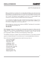
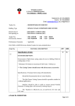
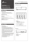
5.2.2. Accessories
1
Power adapter (1) is used to power the
charging device built in the dynamo
graph. When the battery is charging,
the adapter should be plugged in a
socket capable of 220V/50Herz
voltage; the plug (2) should be connec
ted to the interface socket of the
2
07
SIDDOS-mini DYNAMOGRAPH
dynamograph. The adapter is capable of maintaining the charging procedure in the range
of voltage from 190V to 240V. Its output DC voltage is 15V with spikes of 1V and below;
the load current is 300 mA and above.
The car adapter can be used for onsite charging of the dynamograph using DC voltage
from 12V to 27V supplied by the car electric system. ATTENTION! The temperature of
the battery should be in the range from +41F to + 86 F.
The IBM PC interface cable is used to connect the dynamograph to a computer and
transfer data from the tool into the computer database.
The antenna is used for amplification of signal from the remote control.
The remote control is used for controlling of dynamogram test process.
5.3. Tool Operation
5.3.1. Operating Principle
When recording dynamograms, the tool recalculates rod diameter changes into load
changes, simultaneously recording rod movements calculated from the builtin
accelerometer with calculation of pumping speed and stroke length. The survey is started
from the RC unit in the bottom end of stroke of the pumping unit. During the survey, data
received from the sucker rod transducer is processed and stored to memory. Data
processing includes filtering, load calculation from the polished rod diameter, polished
rod movement, maximum and minimum load on the polished rod, recording pump speed
(SPM). Measurements are calculated via two modes: simulation mode of sinusoidal
movements (hereinafter referred to as simulation mode) and mode of calculating
movements via double integration of acceleration signal (accelerometer mode).
Simulation mode is designed for calculation of measurements impossible to record in
accelerometer mode (high noisiness of acceleration transducer signal at slow pump
speed and heavy blows in SRP system for slow pump speed). When operating in
simulation mode it is necessary to enter manually stroke length and mark swinging period
at its two lowest points. In accelerometer mode it is required to input the period at two
points as well, and stroke length, pump speed and movement diagram is calculated
08
SIDDOS-mini DYNAMOGRAPH
automatically according to accelerometer data.
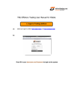
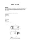
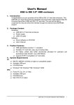
5.3.2. Controls and Indicators
Tool's controls and indicators include:
10digit indicator displaying operating modes,
measurements parameters and results;
Indicator of the tool's clamp tightness;
6button keyboard.
The digital indicator is used to read tool operating modes, control input of id data and
survey parameters, monitor the survey and display its major numeric results.
The keyboard is used to input (modify) the required parameters, input operator's
commands, control all the operation modes both during autonomous operation of the tool
and its communication with external devices. General view, layout and notation of the
Functions of the buttons will be explained in the next section.
09
SIDDOS-mini DYNAMOGRAPH
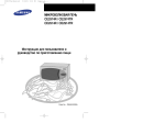
5.3.3. Basic Functions of the Keyboard
1. Switches on the tool.
2. Cycles through the operation modes.
3. Cycles through the position of the flashing (changeable) digit on the display
when parameters are entered or changed.
1. Changes the value of the parameter being set via stepbystep cycling
through the provided options. The parameter being set (changed) is
flashing.
2. Starts data transfer process (to the external devices).
Special service key used as a prefix key. While it is held, the cycling order set by
the MODE and INPUT/OUTPUT keys is reversed. The BACK key significantly
simplifies the procedure of selecting a required value when setting well/cluster
number and other parameters. It also allows correcting accidental keystrokes.
After pressing the BACK button, press the button that needs to be corrected.
Switches off the tool.
Activates single dynamogram mode;
Changes modes of movements' measurement (simulation mode or
accelerometer mode). Changes symbol banks (when entering symbols in id well
parameters).
10
SIDDOS-mini DYNAMOGRAPH
5.3.4. Tool Operating Modes
GENERAL NOTES
1. This section covers tools operation modes and their respective indicators in the
same order as they are cycled through on pressing the MODE key.
2. All the parameters mentioned in this section (number of well and cluster, survey
parameters) can be set in any order irrespective of each other; they are stored in the
tool automatically and remain in its memory even when the tool is switched off until
they are changed again.
3. Verbal records of the set parameters are automatically recorded in alphanumerical
reports of each measurement and added to all the records (including transferring
data into a PC, etc.).
4. For time saving purposes it is recommended to set the necessary parameters before
mounting the tool on a well (on road, etc.).
MODE DESCRIPTION
1. Current load monitoring. The indicator displays the current relative load on the
rod. E.g.:
LOAD 12.34
Current relative load 12.34 klb
2. Last measured results. The indicator displays change of load and stroke length
measured during the last survey. E.g.:
DN12.34L59
Change of load 12.34 klb; rod stroke length 59 in
3. Cluster number. Displays/inputs cluster number. To change the cluster number,
press the INPUT/OUTPUT key, and the first digit (the leftmost) of the cluster number
starts flashing. By pressing the INPUT/OUTPUT key, change the figure to the required
value. Then press the MODE key, and the selected value will be stored in the tool, and you
11
SIDDOS-mini DYNAMOGRAPH
will move on to the next digit, and so on. To return to the previous value or digit, press the
key RETURN and a corresponding key of a value or digit. Apart from digits, this mode
provides the possibility to enter Cyrillic and Latin symbols. To switch banks with 6
symbols, press the key F1 (See Table 1).
Table 1
E.g.:
CLST 00102
Cluster Number 00102
4. Well number. Displays/inputs well number. The procedure is identical to the one for
cluster number described above (mode 3). E.g.:
WEL 023104
Well Number 023104
5. Field id. Indication and input of the field id. The procedure is identical to the one for
cluster number described above (mode 3) E.g.:
FIELD 304
Field id 304
12
SIDDOS-mini DYNAMOGRAPH
6. Polished rod diameter. Displays/edits polished rod diameters (in inches). The
procedure is identical to the one for cluster number described above (mode 3) The range
of rod diameter variation is 0.8...1.53 in. E.g.:
DROD 1.50
Polished rod diameter is 1.5 in
7. Memory. Displays free memory of the tool. E.g.:
MEMORY 320
Free memory for 320 accounts
8. Enhanced modes. Accesses the enhanced mode (additional group of modes) which
is concealed during regular operation on well. To access the enhanced mode, press the
"INPUT/OUTPUT" key, choose “Y” parameter. Then press the “MODE” key and access
the enhanced mode.
NEXT Y
Access to the enhanced mode is allowed
NEXT N
Access to the enhanced mode is not allowed
The enhanced mode includes:
EXACT TIME, INITIALIZATION, BATTERY CELL, TOOL'S NUMBER, DISPLAY
BRIGHTNESS, WORKSHOP NUMBER, OPERATOR'S NUMBER.
ENHANCED MODES:
9. TIME. Displays the current time. Press the "INPUT/OUTPUT" key to zero the
seconds. (if there are more than 30 seconds, value of minutes increases by 1). Clock and
date set up is described in Appendix 5. E.g.:
12:45:30
12 hours 45 minutes 30 seconds
13
SIDDOS-mini DYNAMOGRAPH
10. Initialization. Mode of clearing the tool's memory and time/date set
up/change. Initialization mode is describes in detail in Appendix 4. E.g.:
INITIALIZ N
Initialization forbidden
INITIALIZ Y
Initialization allowed
11. Battery cell. Displays battery voltage and discharge time during antecedent battery
charge cycle. Press the button «INPUT/OUTPUT» to start the process of battery
chargedischarge.
7 .65V05 : 48
The example shows induction of voltage of 7.65 V and charge time equals to 5 hours 48
minutes. Battery handling is described in detail in Appendix 1.
12. Number of the tool. Displays/edits the tool id. The procedure is identical to the one
for cluster number described above. E.g.:
NUMBER 0321
Number of the tool 321
13. Display Brightness. To change the display brightness, press the
"INPUT/OUTPUT" key. Brightness level options13%, 27%, 53%, 99%. E.g.:
BRIGHT 53%
Display brightness is 53% of maximum brightness
14. Shop number. Indication and shop number setup. The procedure is identical to the
one for cluster number described above. E.g
WSHOP 321
Shop number 321
14
SIDDOS-mini DYNAMOGRAPH
15. Operator's number. Displays/sets up operator's number. The procedure is
identical to the one for cluster number described above (mode 3). E.g.:
PIN 415
Operator's Number 415
5.3.5. Switching the Tool On and Off. SelfTest
ATTENTION!
Before you switch on the dynamograph for the first time, after it has not been
used for a long period, or during transportation, please charge the battery cell
(see Appendix 1) before switching on the tool. Otherwise, it is possible that the
tool will not switch on or will switch off automatically immediately after
switching on. This is not a fault symptom.
SWITCHING ON
To switch the dynamograph on, press the “MODE” button and hold it for approx. 1 second.
SWITCHING OFF
When in any operation mode, press the “OFF” button to switch the tool off.
The tool will be switched off automatically:
· if no button has been pressed for more than 3 minutes;
· if any fault has occurred, accompanied by the ERROR message on the indicator;
· if battery voltage is as low as 6,2V.
In the last case, all the data will remain stored in tool's memory, but to prevent deep
discharge the tool needs to be recharged (see Appendix 1).
15
SIDDOS-mini DYNAMOGRAPH
SELFTEST
After switching on the dynamograph, it will perform a selftesting procedure seeking for
any hardware or software errors. If an error has been found, the tool will display its id.
This means that selftest detected:
· either data loss caused by improper handling of the dynamograph;
· or failure of the dynamograph itself.
E.g.:
ERROR 5
Failure in randomaccess memory data
Fif the error was caused by a dynamograph failure, the tool switches off. If the error was
caused by data corruption, when switching on the tool is initialized.
Error ids are listed in the following table:
16
SIDDOS-mini DYNAMOGRAPH
5.4. Storage and Transportation of the Tool
Please store the tool in its standard bag in dry heated rooms with the 14 F to 104 F
temperature range and moisture content of 80% and below.
The tool can be transported in its standard bag using any type of transport at the
40 F to +122 F temperature range.
While storing the tool, check the battery voltage every month and recharge it, if
necessary.
6. PREPARATION FOR SURVEY
The procedures required to prepare the tool for survey are listed in the table, with
references to the corresponding Sections of the present Manual.
1. Preparing the tool for operation Section 6.1
2. Checking the tool Section 4.4.1
3. Mounting the tool Section 4.4.2
6.1. Preparing the Tool for Operation
1. Switch on the tool.
2. Set the survey parameters required for this field (Modes 5, 12, 14, 15).
3. Check the battery voltage (Mode 11) and free memory available (Mode 7). If the
voltage is not enough for operation (e.g.: If voltage is less than 7V, battery
capacity may not be enough for 8 hours of operation), recharge the battery (See
Appendix 1). If the amount of free memory available is less than required, import
the data stored to a PC or to a visual control unit BVK (see Appendix 2), then
initialize the tool in order to delete old data (See APPENDIX 5).
17
SIDDOS-mini DYNAMOGRAPH
4. Set the current time (Mode 9). Adjust if necessary. ATTENTION! If required to
update hours or minutes, than it is necessary to import the data stored to a PC, for
during updating hours or minutes the device memory is previously cleared.
5. Switch off the tool.
The described procedures are not timeconsuming and it is advisable that they are
made on a daily (shift) basis before starting the work shift, and the one listed in
Paragraph 3 should be made beforehand so that there is enough time to recharge
the battery, if required.
7. PERFORMING A SURVEY
ATTENTION! During well work, it is strongly advisable that you follow the Safe
Operation Instruction (Section 4).
ATTENTION! AT LOW TEMPERATURES IT IS REQUIRED TO KEEP THE DEVICE UNDER
THE ENVIRONMENTAL TEMPERATURE FOR NOT LESS THAN 10 MINUTES TO BRING
THE BODY OF A TRANSDUCERR INTO THE OPERATING MODE
1.
2.
3.
4.
Settingup procedures Section 6.1
Equipment fit check (preparation) Section 4.4.1
Survey parameters setup Section 5.3.4
The tool mounting Section 4.4.2
7.1. Accelerometer Mode Measurement
1. Switch on the dynamograph.
2. Enter the well ids.
3. Stop the beampumpingunit (See Section 4.4.1)
4. Place the tool on the polished rod (see Section 4.4.2).
5. Press the “DYNAMOGRAMM” button. The tool will be ready for survey start.
6. Tighten the screw, paying attention to the message displayed on the indicator:
18
SIDDOS-mini DYNAMOGRAPH
OK OK tightness.
À OK (or SCR , or UNS)
А accelerometer mode
Tightness indicator must always be on the display.
Follow instructions shown on the device display:
SCR tighten the tool clamp,
UNS loosen,
OK normal tightness.
Tightness indicator: slow blinking tighten, constant blinking normal tightness, rapid
blinking loosen.
7. Start beampumping unit and miss out threefive pumping cycles.
8. To start the measurement process, press any button on RC unit or the button
“INPUT/OUTPUT” when the polished rod approaches to its lowest position. When
starting the measurement process, a single indicator of clamp tightness fades. The
display shows:
À1
11 the first point of the period has been marked, i.e. the beginning of the next cycle of
walking beam pumping.
9. To mark the second point of the period, when the polished rod approaches its lowest
position for the second time, press once again any button on the remote control or the
button “INPUT/OUTPUT”. The display will show:
À2
2 the second point of the period was marked, i.e. the end of the walking beam pumping
cycle.
The single indicator of clamp tightness flashes continuously until the end of current
measurement of dynamogram.
Thus, by double pressing, the operator marks an approximate duration of one cycle of
walking beam pumping.
19
SIDDOS-mini DYNAMOGRAPH
10. Later, during two cycles of pumping, the device records acceleration and loading into
the memory. Upon completion of measurement record process, the following information
pops up on the display for a short period of time:
À3 6.75s
3 the process of information recording is completed; 6,75s measured period of walking
beam pumping.
11. After measurement recording, dynamograms are calculated. After calculation is
over, measurement results appear on the display for a short period of time:
DN11.9L63
DN11.9 change of load in dynamogram, 11.9 klb (difference of maximum and minimum
loads); L63 stroke length 63 in.
In case of inaccurate dynamogram recording, the display shows the following message:
ERROR RES
In this case it is required to repeat measurement.
12. Then the dynamograph goes into the mode of waiting for the next measurement
launch.
13. To check the results of the last measurement, press the button «BACK» and then the
button «MODE».
14. After all the surveys are complete, unmount the tool (see Section 4.4.3).
7.2. Simulation Mode Measurement
1. Switch on the tool.
2. Enter well ids.
3. Stop the beampumpingunit (see Section 4.4.1)
4. Place the tool on the polished rod (see Section 4.4.2).
5. Switch on the tool, enter measurement mode by pressing the button
«DYNAMOGRAM».
20
SIDDOS-mini DYNAMOGRAPH
6. To switch to the simulation mode, press the button “F1”. If well ids have been
changed, the dynamograph will go into the mode of entering the polished rod stroke
length:
STROKE 59
High order digit is blinking.
7. . Enter nominal stroke length of the polished rod. The procedure is identical to the one
for cluster number described above (see mode 3 Section 5.3.4)
8. After editing the last decade of stroke length upon pressing the button «MODE», the
dynamograph goes into the mode of setting up clamp tightness and waiting for
measurement launch:
C OK (or SCR , or UNS)
С simulation mode of sinusoidal movement.
9. Obtain normal tightness by rotating the screw:
Ok parameter must pop up on the display:
Ñ OK
Follow instructions shown on the tool's display:
SCR tighten the tool clamp,
UNS loosen,
OK ok tightness.
For convenient operation with high wellhead equipment, commands are duplicated on the
additional single LED indicator of clamp tightness: slow blinking tighten, constant
blinking ok tightness, rapid blinking loosen.
10. After setting up clamp tightness of the tool, start beampumping unit and miss out
threefive pumping cycles.
11. To start the measurement process, position yourself next to beampumping unit, and
monitoring the position of walking beam arms, press any button on RC unit (or in other
cases press the button “INPUT/OUTPUT”) when the polished rod approaches its lowest
21
SIDDOS-mini DYNAMOGRAPH
position (at this moment walking beam arms will take strictly vertical position). When
starting the measurement process, the indicator of tightness fades. The display shows:
Ñ1
1 the first point of the period, that is the lowest position of the polished rod, has been
marked, i.e. the beginning of the next cycle of walking beam pumping
12. To mark the second point of the period (end of walking beam pumping period), repeat
point 8 when the polished rod approaches its lowest position for the second time:
Ñ2
2 that the second point of the period was marked, i.e. the end of the walking beam
pumping cycle.
The single indicator of clamp tightness flashes continuously until the end of current
measurement of dynamogram.
Thus, by double pressing, the operator marks the duration of one cycle of walking beam
pumping as well as the moment of the cycle start.
13. Upon completion of dynamogram computation, measurement results pop up on the
display for a short period of time:
DN11.9L63
DN11.9 load change 11.9 klb; L63 stroke length 63 in.
In case of inaccurate dynamogram recording, the following message is displayed:
ERROR RES
In this case it is required to repeat the measurement
14. Then the tool goes into the mode of waiting for the next measurement launch.
15. To check the results of the last measurement, press the button «BACK» and then the
button «MODE».
16. When the survey is over, switch off the tool and then unmount it. (see Section 4.4.3).
22
SIDDOS-mini DYNAMOGRAPH
APPENDIXES
APPENDIX 1. BATTERY CHARGE
The dynamograph is powered from the builtin rechargeable battery with high capacity. To
make the most of the battery service life it is necessary to follow the operation requirements.
An appropriate battery operation is a pledge of smooth operation and longterm reliability of
the tool power supply.
Optimal battery operation is a cycle:
· Discharge of residual battery capacity (supplied by the inbuilt rechargeable battery);
· Full charge (supplied by the inbuilt rechargeable battery);
· Operation (operating discharge);
· The cycle is repeated.
Under optimal operation the battery ensures the tool operation without charging for 24
weeks (it depends upon intensity and temperature conditions of work).
Battery voltage Ua can be monitored on a digital display in a battery voltage control mode.
For a fully charged battery Ua must be within the limits of 7,5V 8,5V. Moreover, the device
possesses Ua limiting value indication:
1). At Ua less than 7.1V the digital display starts changing its brightness with regularity of
0.5 second from 27% to 6%, which warns about need in charging, and at the same time,
about its feasibility. However it is possible to use the tool (for example, in order to finish
the launched survey or data transfer). Nevertheless the battery must be charged for
continuous work.
2). When Ua decreases to 6.6V, the device is switched off automatically, preventing the
battery from substantial discharge. In this case it is required to charge the battery
immediately.
The adapter should be connected to the interface socket of the dynamograph. When
connecting as well as during charging, the tool must be switched off
To recharge the battery, switch the tool off and connect it to a standard 220V/50Hz power
outlet using the power adapter or to a +12V car electric system using the car adapter. Switch
on the tool. Enter the mode of battery voltage indication and press the button
«INPUT/OUTPUT». The following legend will pop up:
7.53D00:00
23
SIDDOS-mini DYNAMOGRAPH
APPENDIXES
Where 7.53 means current battery voltage in Volts, and 00:00 is current time of battery
discharge. At the beginning the tool will discharge the battery until 6 V. After that accelerated
battery discharge will start up.
Charge process is induced on the display:
8.00C08:25
Where 8.00 is current battery voltage in volts, and 08:25 means remaining time for battery
charge.
When the tool is charged the display will be out and the tool will switch off, displaying the
progress on the indicator:
FULLCAPACIT
In case of battery capacity decrease (rapid discharge and charge), or the first switching on
after a long (more than 6 months) storage, as well as for the purpose of preventive measures it
is recommended to conduct battery cycling once per three months.
The procedure of voltage control and battery cycling is described in Appendix 2.
APPENDIX 2.
CAPACITY CONTROL AND BATTERY CYCLING
This mode is designed for evaluation of actual battery capacity and conducting (if necessary)
battery cycling.
If the battery is partially discharged than, in order to control the capacity, it is necessary to
fully charge the battery twice. Battery discharge is generated automatically before the charge.
The time of the previous discharge is fixed in the device memory and shown on the display in
the mode of battery voltage indication.
7 .65V05 : 48
Numbers following the letter «V» (05:48) show battery discharge time before its charge in
hours and minutes. Convert discharge time indications into hours (minutes should be
converted into the tenths of an hour). Multiplying given time by the useful current of the tool in
the mode of accelerated discharge (approximately 0.2А), you will obtain battery capacity in
amperehours (Аh).
24
SIDDOS-mini DYNAMOGRAPH
APPENDIXES
In case capacity is less than 1Аh, than it is necessary to conduct battery cycling or to change
the battery if cycling does not give a desired effect.
For battery cycling it is necessary to conduct three consecutive charge cycles.
To make the most of the battery service life under the conditions of continuous operation,
from time to time it is necessary to conduct cycling procedure (34 times a year).
APPENDIX 3. TRANSFERRING DATA TO A PC
ATTENTION! To avoid errors during data transfer to a PC, it is required to carefully
read and follow the corresponding sections of the User's Manual for the software.
Data transfer procedures are to be performed according to the below following operations.
1. Switch off (if it was on) the tool and connect the supplied interface cable to the
interface socket of the tool and serial port of your PC.
2. Launch the required software on your PC.
3. Switch on the tool.
4. Launch import procedure to a PC database.
APPENDIX 4. Operation with BVK
Using the interface cable supplied along with the BVK visual control unit, connect it to the
dynamograph. Switch on both the dynamograph and BVK. The link between them should
establish automatically, displaying a flag on BVK screen. Data exchange is supported by the
dynamograph in the mode of editing basic parameters. In other modes (enhanced mode,
survey mode) the busy signal will be transferred to BVK. For more information please refer to
BVK Operation Manual.
25
SIDDOS-mini DYNAMOGRAPH
APPENDIXES
APPENDIX 5. SETTING UP DATE AND TIME.
MEMORY INITIALIZATION
This mode allows to reset time, date and clear up the randomaccess memory of the tool.
In this case all the memory content is deleted without the possibility to undelete!
To save valuable data before initialization it is necessary to export them to a PC
database.
During initialization current time and date are not reset automatically and can be kept
without any change or just partially edited.
ATTENTION! It is not allowed to initialize if the battery is discharged (blinking
display), as well as to switch off the tool after launching initialization before the
process is complete.
To initialize, enter the mode Initialization. The following legend will pop up in the display:
INITIALIZ N
In this case the letter N on the right ("no" initialization is not allowed) is blinking. By
pressing the button «INPUT/OUTPUT» set up another letter Y ("yes" initialization is
allowed):
By pressing the button «MODE», enter the mode Current Time. If initialization is allowed
current time is induced with a blinking decade sign showing tens of hours.
14 : 24 : 53
IIf initialization and time set up are not allowed, the device can be switched off.
To continue initialization press the button «INPUT/OUTPUT». Then the initialization
process is being launched and accessrandom memory content is cleaned up. All this time
the display will show a word:
DELETE
After memory clearup the tool is switched on in the mode of current time indication with a
blinking sign at a category of tens of hours (invitation to change).
26
SIDDOS-mini DYNAMOGRAPH
APPENDIXES
Memory initialization is complete. If it is not required to edit date or time, then the tool can
be switched off. In this case, permission for initialization at subsequent activation of the
device will be banned (Inhibition will be restored). It is possible, without switching off the
tool, to enter any operation mode required. In that case it is recommended to ban
initialization in order to avoid its accidental launch when using the tool.
If it is required to set (edit) time or date, change the blinking category of tens of hours
pressing the button «INPUT/OUTPUT». Then, by pressing the button «MODE» go to
units of hours, change them in a similar way, and so on.
After setting units of minutes, press the button «MODE». The display will show a date in
the format [day][month][year], e.g.:
15 / 03 / 05
Set the date by analogy to time setting. After setting up all the categories of date, press the
button «MODE» to transfer the dynamograph into the Current time mode with blinking
categories of seconds. If necessary edit seconds according to signals of exact time by
pressing the button «INPUT/OUTPUT» with the beginning of the 6th signal.
Time and Date setting up is complete. The tool can be switched off or it is possible to continue
operation in the desired mode. As for the latter case, it is recommended to ban initialization.
After initialization, the following parameters need to be set up in the tool:
· cluster number 00001,
· well number 000001,
· field number 001,
· rod diameter 1.50 in,
· stroke length 150 in,
· graph capacity meter 340,
· enhanced mode allowed (y),
· initialization allowed,
· plant number 001,
· operator's number 001,
· display brightness 13%.
27
SIDDOS-mini DYNAMOGRAPH
28