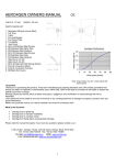
1
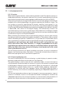
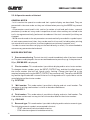
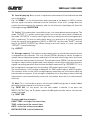
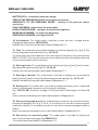
SUDOS-mini 2 LEVEL GAUGE
CONTENTS
1. GENERAL DATA ON THE TOOL
4
2. BASIC TECHNICAL CHARACTERISTICS
4
3. COMPONENTS OF A SET OF DELIVERY
5
4. SAFETY OPERATION INSTRUCTION
4.1 General provisions (normative codes)
4.2 Requirements to the personnel
4.3. Research object
4.4. Equipment assembly and disassembly sequence
6
6
6
6
7
5. ARRANGEMENT AND OPERATION OF THE TOOL
5.1. General information
5.2. Arrangement, application and operation of components
5.3. Operation of the tool
8
8
8
12
6. PREPARATION FOR RESEARCHES
6.1. Preparation of the tool for service
19
19
7. MEASURING
7.1. Fluid level monitoring
7.2. Automatic recording of gas pressure
20
20
21
8. MAINTENANCE
8.1. Schedule of maintenance
8.2. Maintenance procedure
22
22
23
9. STORING AND TRANSPORTATION OF THE TOOL
26
SUDOS-mini 2 LEVEL GAUGE
CONTENTS
SUPPLEMENTS
Supplement 1. Level monitoring under complicated conditions
Recommendations on measurements under complicated conditions
Supplement 2. Setting of a user correction table
Supplement 3. Function of the sound velocity and the annular pressure
Supplement 4. Charging of the battery cell
Supplement 5. Data transfer to the computer
Supplement 6. Visual monitoring unit of BVK series
Supplement 7. Additional modes
Supplement 7.1. Setting of time and date. Initialization of storage
Supplement 7.2. Capacity control and cycling of the battery cell
Supplement 7.3. Setting the pressure gauge at zero
Supplement 7.4. Displaying of the pressure gauge sensitivity
Supplement 7.5. Displaying and setting the tool number
Supplement 7.6. Selection of the display brightness
Supplement 7.7. Setup of the workshop number
Supplement 7.8. Setup of the operator's number
Supplement 8. Testing the tool
Supplement 8.1. Quick test. Restarting the level gauge
Supplement 8.2. Test of recorded echograms
Supplement 8.3. Test of the symbol reports and echograms storage
Supplement 9. Defects discovered while testing the tool
Supplement 10. List of possible defects and methods of their elimination
02
27
27
28
34
36
37
37
38
38
40
40
41
41
41
42
42
42
42
42
43
43
44
SUDOS-mini 2 LEVEL GAUGE
“SIAM” COMPANY THANKS YOU FOR ACQUISITION
OF THE LEVEL GAUGE “SUDOSMINI 2” AND ASKS YOU TO FOLLOW
THESE BASIC REQUIREMENTS WHILE OPERATING IT:
The level gauge is an electronic microcontrolleroperated tool provided with an internal
battery cell, display, keyboard, storage and other tools. While operating it, try to avoid
impacts, strong vibration, attack by acids, alkalis and strong solvents. Do not put the tool
into liquid!
Before turning on the level gauge for the first time, as well as after it's storing for a long
time, firstly, charge the battery cell (Supplement 5.4), and just after that, turn on the tool.
It is always necessary to charge the battery cell until it is fully charged. It is not allowed to
interrupt the charging process, as well as to charge the cell at ambient temperatures of
below zero, because it causes the untimely failure of the tool!
Do not initiate the tool when the battery cell is discharged (the indicator is flashing), as
well as do not turn it on (Supplement 7.1) until the initialization process is completed if it
has been started before.
While initializing, it is possible to refix a date and time in the tool, however, all the
accumulated data can be erased from the level gauge's storage without any possibility of
its reset. Therefore, before initializing, it is recommended to store the measurements
results in the database “DB SIAM”.
This type of level gauge can transfer information to three tools: 1) a personal computer
(PC); 2) a visual monitoring unit of BVK series on the base of a pocket PC; In order to
avoid errors and information losses, when transferring the data to these tools, read
attentively and strictly follow the operational requirements of corresponding software
products and tools. Pay attention to the version of the installed software. This tool
operates in combination with “DB SIAM” of a V2.0version and higher ones.
When tightening the tool on a gauge nipple of a well Christmas tree, it is necessary to use
clips on the body. The use of impact tools and use of the level gauge's case as a lever are
prohibited!
Do not rotate the body and valve when the pressure in the operating body of the tool is
excessive! After the level gauge has been installed, it is recommended to turn the body
and valve in a comfortable position, and only then to open a Christmastree valve. The
neglection of this requirement sharply reduces the lifetime of floating seals.
When using the level gauge, fulfill the requirements of Section “Maintenance” of the
operation instruction! Do not allow internal parts of the tool especially the acoustic
transducer, valve and jointing taper thread to become too dirty, because it causes the
worsening of the tool's operation and reduction of its lifetime.
The level gauge can be repaired only by a service department of the “SIAM” company or
by certified specialists. Unsanctioned breakdown of the tool and violation of operating
rules cause the forfeiture of warranty responsibility!
03
SUDOS-mini 2 LEVEL GAUGE
1. GENERAL DATA ON THE TOOL
The “SUDOSmini 2” level gauge (further called “level gauge”) is intended for prompt
monitoring of the fluid level in oil producing wells. The level gauge provides the monitoring of a
static and dynamic level, recording of fluid level decline and level recovery curves as well as
automatic recording of gas pressure in the annulus at the wellhead. The level gauge can be used
to observe the fluid level while operating wells, as well as while putting them into operation
after their repair or outage.
2. BASIC TECHNICAL CHARACTERISTICS
1. Range of monitored levels
monitoring resolution
659800 (19 685)* ft / 206000 m
3 ft
2. Range of monitored pressures
monitoring resolution
(01422) psi / (0100) bar
1 psi / 0.1 bar
3. Offline storage capacity
for symbol reports
for graphs
3008
310
4. Time of continuous operation under normal
climatic conditions and after the battery cell
has been fully charged, not less than
10 hours
5. Time of charging of a discharged battery cell
10 hours
6. Time of data storage in the offline storage ,
not less than
5 years
7. Operating range of temperature
40 F to + 122 F/ 40°C to +50°C
8. Service life
5 years
9. Bulk, not more than
5.5 lb / 2.4 kg
* — Option
04
SUDOS-mini 2 LEVEL GAUGE
3. COMPONENTS AND DELIVERY SET
05
SUDOS-mini 2 LEVEL GAUGE
4. SAFE OPERATION INSTRUCTIONS
4.1. General provisions (normative codes)
· The construction of the wellhead equipment should correspond to the scheme approved
by the State municipal engineering supervision bodies1.
· Preparation of a well for researches and carrying out of the researches should be
performed in accordance with the requirements of the Instruction and internal well
servicing and researches instructions approved by the head of the enterprise.
· Research equipment should be operated according to the operational instruction
delivered with the equipment by the manufacturing company.
· Safety measures are regulated by instructions of labor protection for appropriate types
of work, approved by the labor protection department of the enterprise and by “Safety
regulations for the oil and gas industry” approved by the State municipal engineering
supervision body of Russia1.
4.2. Requirements to the personnel
· Only people who are 18 years and older, who have a secondary or higher education and
are in health conditions allowing them to work in this area are permitted to carry out well
researches.
· The personnel should be professionally trained, examined and have a special permission
to conduct the works according to the job specifications.
· The personnel should be trained to operate on the research equipment. The training is
performed by employees of the manufacturing company directly on the working place.
4.3. Research object
Such researches as pressure measuring and fluid level monitoring are carried out on oil
and gas producing wells of different operation types (fountain, gaslift, mechanized
extraction and other ), as well as on injection, waterintake, monitor and other wells.
4.3.1. Requirements to the research object
· Construction and operation of a well should be performed in accordance with “Safety
rules in the oil and gas industry”.
· A well researched, irrespective of its application and operation mode, should have a
technological tap equipped with a valve and a wave metering tool seating nipple. A fluid
level determination is possible only in that space of the well (tubular, tubular annulus, hole
annulus, string annulus) which connects with the used technological tap. While carrying
out the measurements, there should not be any neckings (connections, dosimeters and
similar tools) in the tap. The nipple of the technological tap should have the pipe taper
thread of 60, 2" size, "male" or "female" type. The nipple of the technological tap should
06
1
Only in The Russian Federation
SUDOS-mini 2 LEVEL GAUGE
be placed at the height of 3.3 5.9 ft above the ground. When the nipple is at the height of
more than 5.9 ft above the ground, it is necessary to use stationary or portable platforms
if they are appropriate to the “Safety regulations for the oil and gas industry1. The nipple
which is not being used at the moment should be blanked off.
· In the way of an acoustic pulse, not more than two bends of the conduit at the angle of
90° and at the distance of 65.6 ft away from the nipple are admissible.
4.4. Equipment assembly and disassembly sequence
4.4.1. Surface equipment preparation
· Make sure that the valve of the technological tap and a pressure gauge are in running
order.
· Check that the pressure in the well researched annulus is in the range of that of the
minimally permissible pressure of the tool.
· Remove the end cap from the technological nipple. Clean the taper thread from sludge,
oil, sand and etc. Check the compliance of the tread with the requirements mentioned
above. In cases when a thread type does not comply with the requirements, as well as if
there is an undue wear, massive corrosion or damages of the nipple's thread, carrying out
researches is prohibited.
· Clean the inner space of the nipple from paraffin, hydrates, ice and other.
· If the nipple of the technological tap is "male" type assembles the level gauge directly. If
nipple is a "female" type use adapting pipe for assembly.
4.4.2. The level gauge assembly sequence
· Clean the thread part of a coupling of the level gauge from sludge and check it. If there is
an undue wear, massive corrosion or damages of the thread, the assembly of the level
gauge is not permitted.
· Open the valve in the technological tap for a while (for 12 sec.) in order to blow it
through (to clean it from condensate, ice, sludge and other plugs).
· Install the level gauge screwing it on as far as it will go on the nipple and turn it tight in
order to avoid a displacement of the level gauge when it is under pressure. A tightening
torque should be not less than 285±43 psi. To tighten the thread, use the clips on the
thread coupling of the level gauge and a handle from a tool set. It is possible to use any
appropriate lever instead of the handle.
· ATTENTION! When tightening, it is prohibited to use impact tools and the
rotating body of the level gauge as a lever.
· Turn the valve head in such a way that no gas escape hole is towards you.
· Check whether the nut of the level gauge's outlet valve is tightened well, if not, turn it tight.
· Turn the tool's body with the display and keyboard in a position comfortable for access
and observation.
· ATTENTION! It is allowed to rotate the rotating body and valve only if there is no
pressure in the working body of the level gauge.
07
SUDOS-mini 2 LEVEL GAUGE
· Lift off the keyboard and display cover and set up the tool in a pressure monitoring mode.
· Gradually, not causing a pneumatic or hydraulic impact, open a gate valve until gas starts
entering the level gauge. Stop the gate valve opening for a while in order to smooth the
pressure in the well and in the tool's working body, and, then, open the gate valve
completely. A pressure smoothing process should be controlled with the tool's display in
pressure monitoring mode.
· In order to avoid a thread joint gas leakage, use thread sealing lubrication or a sealing tape.
4.4.3. Level gauge disassembly
· Turn off the tool.
· Close the gate valve of the technological tap.
· Open an outlet valve of the tool and let the excessive pressure out of the working body.
· Screw out the level gauge and take it off the nipple. Drain the working body off the
condensate, clean a thread part and house the tool in its bag.
· Place the end cap on the nipple.
5. ARRANGEMENT AND OPERATION OF THE TOOL
5.1. General information
The SUDOSmini 2 level gauge is a compact electronic monounit tool. It is a completely
independent tool and provides all functional abilities of a well level gauge. The tool is capable
to display all basic monitoring parameters and results immediately.
The level gauge maintains the data export to a PC or viewing unit of BVK series. An applied
software DB “SIAM” included in the delivery set, makes it possible to create and add computer
data bases, to process and analyze measurement results in more detail.
5.2. Arrangement, application and operation of components
5.2.1. SUDOS mini 2 level gauge
The level gauge is intended to generate acoustic pulses in the annulus, to receive and
convert an acoustic response (an acoustic signal), as well as to determine the fluid level and
to monitor pressure at the well head. The tool operates according to its internal program
controlled with a builtin microprocessor controller which synchronizes the operation of all
the components, processes the data transferred from primary transducers, performs a level
calculation, displays the operation modes and monitoring results on a digital display, as well
as it registers measurement parameters and results in its fixed storage, and ensures a
communication with external devices (a computer and a visual monitoring unit).
The level gauge operates on a builtin battery cell with a life resource of not less than 1000
“chargedischarge” cycles. To charge the cell, in the level gauge there is a builtin
programm controlled charging device allowing to service the battery cell correctly.
08
SUDOS-mini 2 LEVEL GAUGE
5
The level gauge contains:
1 a rotating removed outlet valve;
2 a rotating body of the tool;
3 two install clips;
4 a thread jointing coupling;
5 a symbol display;
6 a keyboard;
7 an auxiliary slot to connect external devices
such as a mainsoperated adapter, a cable
for charging from car power, a computer
and a visual monitoring unit.
6
7
1
2
3
4
When monitoring the fluid level, the level gauge is installed directly on a gauge nipple of
the well Christmas tree, and measuring cables are not required. The control and display
units are placed on the rotating body and have a protective cover. The body with the valve
and control and display units can be positioned conveniently by rotating it about its
longitudinal axis in any direction and at any angle (up to 360°). The outlet valve can also be
rotated freely about its longitudinal axis in order to fix an outlet hole in a position not
towards an operator.
ATTENTION! It is allowed to rotate the body and the outlet valve only if there is no
excessive pressure in the working body of the level gauge.
5.2.2. Mainsoperated adapter
The mainsoperated adapter is intended to power a
charging device built in the level gauge. When charging a
battery cell, the adapter is connected to an industrial
supply line of 220V/50Herz, and its plug is plugged in
the auxiliary slot of the level gauge. The adapter ensures
appropriate parameters of charging when the line
voltage is from 190V up to 240V. At the current load of
not less than 300 mA., its outlet d.c. voltage is 12V with
spikes of not higher than 1V.
8
9
5.2.3. Cable for charging from car power
A cable makes it possible to charge the level gauge with
a fixed voltage of 12V up to 27V from the car power
supply under the field conditions. Attention! The battery
cell's temperature should be in the range of + 30 F up to
+86 F.
09
SUDOS-mini 2 LEVEL GAUGE
5.2.4. Interface cable
The interface cable IBM PC is intended to connect
the level gauge to a computer and to transfer data
from the tool to a computer data base.
5.2.5. Handle
The handle ensures convenient assembly and
disassembly of the level gauge on a well; and the
handle is of a great length and strength that makes it
possible to tighten (with an adequate moment) (see
Section 4.4.2) the level gauge on a measuring nipple
with the help of install clips on a rubber jointing
coupling of the level gauge without the use of any
other tools.
5.2.6. Spare parts
Rubber sealing rings are placed in a surface turning
of the body and in a removable seat of the valve.
They should be replaced in case if this joint is worn
out or is not hermetically sealed.
A set consisting of two split guard fluoroplastic
rings and a rubber ring is intended for replacement
of a rotating “the couplingthe body” sealing in case
if the latter is not hermetically sealed. The
replacement of wornout parts is performed
according to the level gauge's maintenance
instructions described in Section 8.
5.2.7. Additional accessories
·Acoustic pulse generator GAI01
The acoustic pulses generator GAI01 is used to
generate the acoustic effect when there is no
excessive pressure in the well's annulus. The GAI01
may also be used to monitor the fluid level down up
to 5905 8202 ft. when the annular pressure is
10
SUDOS-mini 2 LEVEL GAUGE
rather low. The GAI01 has a reservoir for
accumulating the excessive air pressure (a
receiver), a hand pump, a transportation lock and a
valve for quick draining off which are integrated
into one body. In the handle the spare rings for the
GAI01 are placed.
· Visual monitoring unit BVK
The BVK is used to visually monitor measurement
results in tabular as well as in graphic form, to
determine the level more accurately using acoustic
signals graphs, to record these data in its storage
and then to transfer them to the computer
database. While doing so it is still possible to
collect measurement results in the level gauge itself
and then to transfer them to the computer. The BVK
is manufactured on the base of an uptodate Palm
PC and is housed in an impactresistant body. The
BVK is connected to the level gauge by means of
cable. The acoustic signal graph is displayed exactly
at the moment of carrying out the measurement.
· Adapting pipe
Adapting pipe is used to connect the nipple of the
technological tap of “female” type with the level
gauge of “female” type.
11
SUDOS-mini 2 LEVEL GAUGE
5.3. Level gauge operation
5.3.1. Function
When monitoring the fluid level, a wave metering method is used. The operation process is
rendered automatically. An operator takes part only in acoustic pulse generation with the
help of either the outlet valve of the level gauge or additional devices (such as GAI01).
An acoustic pulse passes through the well annulus from the level gauge to the fluid level
and back with a velocity depending on the physical and chemical conditions of gas. The
tool monitors an acoustic signal during 20 seconds, amplifies it and records it in its
storage. Simultaneously the gas pressure in the annulus is also determined and recorded
in the storage. While analyzing and processing the recorded data, the fluid level in the well
is determined, then shown on the digital display, and automatically stored in an
nonvolatile memory of the tool as a symbol report. Recorded results including a complete
echo gram of the acoustic signal can be printed out with a micro printer and transferred to
a visual monitoring unit or a computer database.
When calculating the fluid level, the tool automatically selects an acoustic pulse velocity
according to one of the sound velocity tables recorded in it. The number of the correction
table is selected by the operator. In addition to it, it is possible not to use the tables, but to
set a sound velocity (irrespective of pressure and level) manually using the keyboard.
According to our experience, the sound velocity in wells can greatly vary even
within one and the same field. Therefore, it is highly recommended to use your
(applied for your region) correction table for an individual field or a group of wells
within the field. In any case, the tool will display a level based only on the sound
velocity that has been set in it!
The tool analyses the level of all signals including noise signals, as well as it evaluates a
degree of an interference effect, and, when it is necessary, automatically activates (or
deactivates) a program filter of interference suppression.
5.3.2. Control and display units
The control and display units are the following: a symbol display of operation modes,
parameters and measurement results and a fourkey keyboard.
The symbol display is used to show the tool's operation modes, to control the input of
initial parameters (reference data) of a research, to monitor the research in progress and
to display basic numerical results of the research. When the information is transferred
and presented, a digital display serves as a symbol display applying “appropriate”
combinations of Russian and Latin alphabets. Hence, the digital display provides a
minimal necessary set of functions completely supporting an independent operation of
the tool.
The fourkey keyboard provides an input (a change) of necessary parameters, input of
operator's commands, control of all the operation modes including both a mode of the
independent operation of the tool and a mode of its communication with peripherals. A
general view, layout and notation of the keyboard's keys are shown in the picture.
12
SUDOS-mini 2 LEVEL GAUGE
The functional duties of the keys are
described in more detail in the next section.
5.3.3. Basic functions of the keys
MODE key makes it possible to
· Turn on the tool.
· Сonsecutively look through (in a closed cycle) the operation modes.
· Сonsecutively look through a number of flashing (changeable) digit place
position on the digital display when entering (or changing) parameters.
INPUT/OUTPUT key makes it possible to
· Turn on the tool.
· Change a value of a set parameter stepbystep (cycling) looking through
the provided alternatives. The set parameter (being changed) is displayed
as a flashing free space sign. This means that a parameter may be entered.
LEVEL key makes it possible to
· Turn on the tool.
· Starts a fluid level measuring process.
· Shange over the tool from any mode back to the initial one by
consecutive pressing the LEVEL and MODE keys (move back/ reset).
· Turn the tool off by consecutively pressing the LEVEL and
INPUT/OUTPUT keys.
BACK
· This special service key is used as a prefix key. It changes the operation
of the MODE and INPUT/OUTPUT keys (only if the BACK key is pressed at
that moment). The BACK key significantly simplifies the procedures of
selection of a required digit when setting a well and a well cluster number
and other parameters, as well as it makes it possible to correct a mistaken
keystroke.
13
SUDOS-mini 2 LEVEL GAUGE
5.3.4. Operation modes of the tool
GENERAL NOTES
· In this section the operation modes and their symbol display are described. They are
presented in the same order as they are initiated when pressing the MODE key several
times.
· All parameters mentioned in this section (a number of well and well cluster, research
parameters) can be set in any order irrespective of each other and they are stored in the
tool's storage automatically (and remain stored even if the tool is turned off) until they are
changed.
· Word records made to the set parameters are automatically recorded in a symbol report
of each measurement and, then, they can be read in all records (including when printing
out records with a micro printer, transferring data to a stationary computer, etc.).
· In order to save time when carrying out the work directly on a well, it is recommended to
set necessary parameters beforehand.
MODES DESCRIPTION
1. Pressure monitoring. The tool starts this mode immediately after it has been turned
on. The pressure displayed is the current wellhead annulus pressure, e.g. if the pressure is
82 psi, PRESS 82P is displayed.
2. Cluster number. This mode makes it possible to display and to set a cluster number.
To change a cluster number, press the INPUT/OUTPUT key, and the first digit place of
the cluster number (the last left figure) starts flashing. Change the figure up to the
required value by pressing the INPUT/OUTPUT key consecutively. Then press the MODE
key and the figure selected is stored in the tool's storage and now it is possible to set the
next digit place of the cluster number.
E.g. CLST 5281
3. Well number. This mode makes it possible to display and set a well number. The
sequence of setting a well number is similar to that described above.
E.g. WEL 43231
4. Field number. This mode makes it possible to display and set a field number. The
field number can be reset in a way similar to those described for the cluster number.
E.g.: FIELD 432
5. Research type. This mode makes it possible to display and to select a research type.
The following research symbols are accepted in the tool:
· STAT denotes a static level determination;
· DYN denotes a dynamic level determination;
14
SUDOS-mini 2 LEVEL GAUGE
· LRC denotes the recording of a level buildup;
· LDC denotes the recording of the level builddown;
· GPC denotes an automatic recording of gas pressure.
To select a research type, it is necessary to press the INPUT/OUTPUT key
consecutively up to the required research type.
E.g.: TYP DYN, i.e. a dynamic level determination research type has been selected.
6. Period mode. This mode is appropriate only for automatic recording of gas
pressure. This mode makes it possible to display and to set an interval of the tool's
operation (in terms of minutes) when automatically recording an annulus pressure.
The possible alternatives are: 1, 2, 3, 4, 5, 6, 7, 8, 9, 15, 20, 30, 40, 50, 60, 70, 80, 90. The
interval is selected by pressing the INPUT/OUTPUT key consecutively.
E.g.: PERIOD 8, i.e. an 8minute interval has been chosen.
7. Number of measurements. This mode is active just for automatic recording of gas
pressure. This mode makes it possible to display and to set the number of measurements
during automatic recording of gas pressure. The possible alternatives here are as follows:
““, 1, 2, 3, 4, 5, 7, 10, 15, 20, 30, 40, 50, 70, 100, 150, 200, 300, 400, 500, 600, 700, 800,
900, ““,. The symbol ““ indicates the infinite number of measurements. While this the
level gauge will be operating in an independent mode until the operator goes to Mode 1 or
2, or until the battery cell discharges.
E.g.: NUMBER 15, i.e. 15 measurements will be conducted.
8. Table. This mode displays and selects a number of user (working) tables of the sound
velocity. A factory basic version contains three alternatives:
· 0 there is no table at all (the sound velocity is set manually);
· 1 there is a table appropriate for a Siberian region of Russia (see Supplement 3);
· 2 there is a table appropriate for a European region of Russia (see Supplement 3).
In addition to it, using a computer and a database, it is possible to install any of four user
tables (see Supplement 2 for more detail). A user table (of the tables already installed in
the tool) is selected by pressing the INPUT/OUTPUT key consecutively.
E.g. TABLE 15, i.e. a user table of Number 15 has been selected.
9. Speed (of the sound velocity). This mode is initiated only in case when Table 0 (i.e.
the sound velocity should be set manually) is selected. Firstly the sound velocity (m/sec.)
set earlier is displayed. In order to set a required value of it, follow the same sequence as
that of setting a cluster number or a well number. A sound velocity can be manually set in a
range from 600 up to 1999 ft/sec.
E.g.: SPEED 1083, i.e. a sound velocity of 1083 ft/sec has been set.
15
SUDOS-mini 2 LEVEL GAUGE
10. Level displaying. Basic results of a previous measurement of the fluid level are read
out on the display.
E.g.: L 2 3380 F, i.e. the fluid level has been measured at the depth of 3380 ft, and an
acoustic signal was twice reflected from the fluid level. If the tool's storage does not
contain any measurement (for example, after its initialization), the display will show the
following message: UNCERTAIN.
11. Outlet. This mode makes it possible to start/run a level determination program. The
mode “OUTLET Y” is used in case of gas outlet from a well (an outlet valve is used here);
the mode “OUTLET N” is used in case of gas inlet into a well (an acoustic pulse generator
GAI is used here). To work on wells where there is no pressure at all (a zero pressure)
(using the acoustic pulse generator GAI01 or GBO02), set the mode “INLET” with the
help of the INPUT/OUTPUT key. When setting a new well cluster or a well, the mode
“OUTLET” is set automatically.
E.g.: OUTLET
12. Storage capacity. The vacant storage capacity left to record measurement results
is displayed on two counters. The first counter (SR ¹.) displays a vacant storage for
symbol reports (digital parameters and results of the level monitoring) and it shows one
less after each measurement of the level. The second counter (SR ¹.) shows the vacant
storage for measurements graphs and it also displays one less after each performance of
a graph recording operation when the level has been measured. E.g.: SR120GR 11, i.e. in
the storage there is enough room for recording 120 symbol reports and 11 graphs.
The total capacity of the storage is adequate for 3008 symbol reports and 310 graphs.
The counters return to the initial storage capacity when they are initialized or data are
transferred to a computer. If the storage is completely full, a recording of every following
measurement result automatically erases the information about the first measurement
and so on.
13. Next. This is the mode of access into the next (additional) group of modes hidden
during the ordinary operation of the tool on a well.
E.g.: NEXT NO, i.e. the access into the next modes is denied. If we press the
INPUT/OUTPUT key, the Y symbol replaces the N symbol and the access into the next
modes is allowed.
E.g.: NEXT YES
The next (additional) modes:
EXACT TIME setting of the exact time;
TIME reflection of the current time;
DATE reflection of the current date;
INITIALIZATION tool initialization;
16
SUDOS-mini 2 LEVEL GAUGE
BATTERY CELL internal accumulator voltage;
ZERO OF THE PRESSURE GAUGE zeroing pressure sensor;
SENSITIVITY OF THE PRESSURE GAUGE setting of the pressure sensor
sensitivity;
TOOL'S NUMBER reflection of the tool number;
DISPLAY BRIGHTNESS setting of the indicator brightness;
WORKSHOP NUMBER setting of the workshop;
OPERATOR'S NUMBER setting of the PIN.
14. Initialization. This mode makes it possible to clear the tool's storage and set
(change) the date and time. INITIALIZ N
In details the initialization mode is described in Supplement 7.1.
15. Time. This mode makes it possible to display a current time ([hour].[min.].[sec.]). The
two last digit places (seconds) flash. E.g.: 14 : 24 : 53
To correct the time in accordance with the sixth signal of the precise time, press the key
INPUT/OUTPUT. The seconds will be set at zero and the minutes will be expressed in the
closest round number to the current time.
16. Setting of time. This mode displays the current time (in [hour].[min.].[sec.] format).
Digit places being set are flashing. E.g.: 14 : 24 : 53
In details the time setting mode is described in Supplement 7.1.
17. Setting of the date. This mode makes it possible to display the current date (a
[date]. [month]. [year] format). Digit places being set are flashing. E.g.: 15/11/01
In details the date setting mode is described in Supplement 7.1.
18. Battery cell. This mode makes it possible to display the battery cell's voltage and
time of its discharging in a previous cycle of the cell's charging.
E.g.: 7 .65V12 : 48, i.e. the cell's voltage is 7.65 V and time of its discharge is at 12 hour 48
min.
How to work with the battery cell is described in details in Supplement 4.
19. Set pressure gauge to zero. This mode displays a correction for zero drift and sets
the pressure gauge to zero. E.g.: Z 7 8.6 , i.e. a correction for zero drift of an echogram
amplitude is equal to 7 units and a correction for zero drift of a pressure gauge is equal to
8.6 bar.
How to set the pressure gauge to zero is described in details in Supplement 7.4.
20. Sensitivity of a pressure gauge. This mode makes it possible to display the
sensitivity of the pressure gauge. E.g: SENS 112.5
This mode is described in details in Supplement 7.5.
17
SUDOS-mini 2 LEVEL GAUGE
21. Number of the tool. This mode makes it possible to display and set the tool's
number. E.g.: NUMBER 0381
The operation in this mode is described in details in Supplement 7.6.
22. Display brightness. This mode makes it possible to display and to select the display
brightness. E.g. BRIGHT 53%
The mode is described in details in Supplement 7.7.
23. Workshop number. The mode makes it possible to display and to set a workshop
number. E.g. WSHOP 321
The mode is described in more detail in Supplement 7.8.
24. Operator's number. The mode makes it possible to display and to set the operator's
personal identification number. E.g. PIN 415
The mode is described in more detail in Supplement 7.9
5.3.5. Turning the tool on and turning it off
ATTENTION! Before turning on the tool for the first time after it has been stored
for a long time or transported, it is necessary to fully charge the battery cell (see
Supplement 4). Only after having charged the battery the tool may be turned on.
Otherwise, the tool cannot be switched on or it can switch off immediately after
having been turned on. But this does not mean that the tool has any default.
SWITCHING ON
Pressing one of the three keys turns on the tool: MODE, INPUT/OUTPUT, LEVEL.
After being turned on the tool remains in the same operation mode as it was in
before turning off, if none of the keys are pressed within a period of longer than
100 sec.
SWITCHING OFF
The tool can be turned off from any operation mode by pressing consecutively the keys
LEVEL and INPUT/OUTPUT. To turn the tool off from the annulus pressure monitoring
mode, press the key INPUT/OUTPUT.
The tool goes off automatically:
· If none of the keys are pressed within a period of longer than 100 sec.;
· If any malfunctions accompanied with displayed notes like ERROR occur (in this
case the tool goes off within a 20second period);
· If the battery cell's voltage decreases down to 6.6V.
In the latter case all the information stored in the tool are saved, but in order to prevent a
full discharge of the battery cell, it is necessary to charge it (see Supplement 4).
18
SUDOS-mini 2 LEVEL GAUGE
6. PREPARING FOR WELL TEST
ATTENTION! When preparing researches, assembling and disassembling equipment,
please strictly follow the requirements of the Safe Operating Instruction (Section 4).
Successive stages of preparation for researches are presented in the table with references to
the appropriate sections of the Instruction:
1. Preparation of the tool for service see Section 6.1
2. Checking of the surface equipment to be available for service (preparation for service) see Section 4.4.1.
3. The level gauge assembly see Section 4.4.2.
4. Setting of research parameters see Section 5.3.4:
Setting of a well cluster and a well number, a field number and a research type,
required parameters of the research see section 5.3.4.
6.1. Preparation of the tool for service
The procedure of preparation of the tool for service is rather simple and it involves the
following operations:
1. Turn on the tool (see Section 5.3.5).
2. Check voltage of the cell and, when necessary, charge it (Supplement 4).
4. Check a current time and, when necessary, correct it (Supplement 7.1.).4. Check the
vacant storage capacity. If there is not enough room for results of forthcoming work and
data stored in the storage are still important, it is necessary to save them by transferring
them to a computer (Supplement 5) or to a visual monitoring unit (Supplement 6).
5. Turn off the tool.
The steps mentioned above take minimal time and it is recommended to carry them out every
day (every shift) before a working shift. It is highly recommended to check the battery cell's
voltage beforehand in order to have time to charge it if necessary.
19
SUDOS-mini 2 LEVEL GAUGE
7. MEASURING
ATTENTION! While performing work on a well, strictly follow the requirements and
provisions of the Safe operating Instruction (Section 4).
7.1. Fluid level monitoring
Install the tool on the nipple of the technological tap (see Section 4.4.2). If the nipple of the
technological tap is "male" type assemble the level gauge directly. If nipple is a "female" type
use adapting pipe for assembly. After having placed the tool in a position comfortable for
access to the keys and observation of the display, turn it on and set (if they have not been set
beforehand) a number of a well and a well cluster, a research type and other necessary
parameters.
When using acoustic pulse generator GAI01,
change over the level monitoring program in a
position of gas inlet into the well (Mode 9).
Press the LEVEL key and keep it pressed for about
one second until the l symbol appears on the
display. It means that the tool is ready for level
measuring. During this onesecond pause the level
gauge measures a noise level in the well and
automatically determines a necessary operation
threshold.
The digit place in which the I symbol is displayed
depends on the noise level: the higher the noise, the
more right the I symbol appears.
Generate an acoustic pulse by pushing stop on the handle of the tool's outlet valve. The next 20
seconds after an acoustic pulse has been generated the tool detects and records acoustic data
from the well. Acoustic data detection can be observed on the display showing the signal peak
level in 50 gradations (the more right the symbol moves the higher the noise level is). After 20
seconds the L symbol appears on the display. This symbol shows that the detection and
recording of acoustic data have been finished and the tool is in mode of echogram analysis
and level calculation.
In 1 or 2 sec. after the beginning of calculations, a level measurement result is displayed. E.g.:
L 2 3380F, i.e. the fluid level has been measured at the depth of 3380 ft, and 2 reflections of an
acoustic signal from the fluid level have been recorded.
20
SUDOS-mini 2 LEVEL GAUGE
For each calculation the calculated value of the fluid level, the number of reflections, research
parameters and a graph are automatically recorded into the tool's storage for symbol reports
and into the storage for echograms combined with symbol reports. Hence, symbol reports are
recorded into the echograms storage and are duplicated in the storage for symbol reports.
To make the monitoring results more reliable, it is highly recommended to reconduct the level
measurement. If the measurement results significantly differ from each other, it testifies that
the tool cannot determine the fluid level automatically. This can be caused by different reasons
(some of them are considered in Supplement 1). In this and as well as in other doubtful and
necessary cases, it is recommended to determine the fluid level according to an acoustic signal
graph. One can get an acoustic signal graph when transferring measurement data to one of the
tools, i.e. a personal computer, a visual monitoring unit.
7.2. Automatic recording of gas pressure in the wellhead annulus
Insall the level gauge on the nipple of the technological tap (see Section 4.4.2).
After having placed the tool in a position comfortable for access to the keys and observation
of the display, turn it on and set (if they have not been set beforehand) a number of a well and a
well cluster, an automatic gas pressure recording research type (GPC mode) (Mode 4) and an
interval of the tool's operation (Mode 5). Press the LEVEL key. The display will show START
GPC.
The level gauge starts its operation in 5 seconds and it will automatically come on in a set time
period, operate during 0.2 sec. (it measures the pressure and records the measurement result
in the storage), automatically go off, and so on. It is recommended to select such a period of
measurements so that within a total operation period the tool makes not more than 3008
measurements.
To interrupt the GPC mode, select the modes of STAT or DYN research type.
21
SUDOS-mini 2 LEVEL GAUGE
8. MAINTENANCE
8.1. Schedule of maintenance
The tool's maintenance (M) is subdivided into 4 groups depending on an operation interval and
is presented in the table below.
22
SUDOS-mini 2 LEVEL GAUGE
8.2. Maintenance procedure
ATTENTION! When using petrol and alcohol follow the rules of fire prevention! Carry
out the work only in wellventilated rooms.
8.2.1. Cleaning of the taper joining thread, the acoustic transducer, the pressure
gauge and the face panel.
When cleaning, use clean petrol, a brush and cleaning cloth. It is possible to pour out a
little petrol into the inner space of the thread jointing coupling. However, do not
submerge the tool body into liquid to clean it, and not allow the liquid to be spilled on the
panel of the keyboard and the display, and into the auxiliary slot. When cleaning the
heavily dirty thread, one may use such metallic instruments as an awl, a screwdriver, etc.
However, while doing it, do not use force! The acoustic transducer's body is covered with
protective vanish, do not damage it! It is prohibited to put any things into the hole of the
pressure gauge!
After having cleaned the tool, wipe over its surface with cleaning cloth. Cleaning should
result in a bright metallic luster of inner surfaces of the coupling, the joining thread, the
acoustic transducer and clean holes of the pressure gauge and the union.
This figure illustrates the construction
components location in the inner space of the
thread joining coupling of the level gauge: 1 an
acoustic transducer; 2 a pressure gauge; 3 a
union.
It is allowed to clean the face panel with clean
cleaning cloth slightly wetted with glass
washing liquid. After that, wipe over the panel.
In order to avoid scratches on the glass (the
lightfilter of the display), not make great
efforts while cleaning and wiping it over.
External surfaces of the tool (except of the
face surface) are wiped over with clean
cleaning cloth slightly wetted with petrol and
then, are wiped dry.
1
2
3
8.2.2. Maintenance of the outlet valve
The outlet valve is cleaned with clean petrol, a brush and cleaning cloth. Before cleaning,
remove the valve from the level gauge, place it into a clean reservoir and pour out a little
petrol. Not taking the valve out of the reservoir, push the handle several times. Clean the
external surfaces with a brush. Do not leave the valve into petrol for a long time. After
washing the valve, wipe it dry with clean cleaning cloth. Before placing the valve back into
23
SUDOS-mini 2 LEVEL GAUGE
the level gauge, lubricate slightly the surface of a rubber sealing ring (7) with lubrication.
After the valve has been installed into the tool, assemble the latter on a level gauge tests
bench GMS1 (gauge monitoring stand) and blow through the valve with clean air at the
pressure of 71...114 psi. Test the valve for leakproofness with soap lotion/dilution.
Slight leaks indicated by formation of small air bubbles around the outlet hole is
permissible. If the valve leaks more than permissible, rewash it. In case if the leak is not
stopped even after the rewashing, replace the valve couple (valve tappet with ball (4) and
the valve seat (3)). To do this, carefully compress the retaining ring (5) and pull it out of the
valve body. Take a guide bushing (1), a spring (6) and the valve tappet with a ball (4) out
from the valve body. Take the seat (3) and the sealing ring (2) out from the valve body too.
1
5
6
2
3
4
7
Replace the valve couple and reassemble the valve in reverse order; while reassembling,
lubricate slightly the surface of the rubber sealing ring (7) with the lubrication.
The seat has a face (bevel edge) on the outer diameter. The face is of small dimensions
and, therefore, before assembling, it is necessary to determine accurately whether it is at
its place. The seat should be installed in such a position that the face “looks” inside the
body.
8.2.3. Cleaning of the auxiliary slot for connection of peripherals
To clean the auxiliary slot, pure ethyl alcohol or alcohol. Alcohol consumption is 30 gr. per
month of operation. After cleaning, lubricate slightly the surface of the auxiliary slot with
the lubrication.
24
SUDOS-mini 2 LEVEL GAUGE
8.2.4. Operation monitoring
Monitoring of basic operational parameters of the level gauge is performed for the
following operation modes:
1) Check of setting of adjustment and displaying modes;
2) Check in the level and pressure monitoring mode;
3) Check of sensitivity and noise level of an acoustic path;
4) Check in the mode of automatic pressure recording;
5) Check of monitoring of the maximal operation pressure (not more than 1422 psi);
6) Check in the mode of monitoring of the battery cell's capacity.
The check technique is presented in “The instructions to conduct check tests of tools and
systems manufactured by the “SIAM” company when they are in operation”. The Checks 2
and 3 are conducted on the level gauge tests bench GMT1(gauge monitoring stand)
(“SIAM” company). Check 5 is conducted on the hydrostatic tests bench HTS1 (hydraulic
test stand) (“SIAM” company).
8.2.5. Pressure test
A pressure test of the tool is carried out on a hydrostatic tests bench HTS1(hydraulic
test stand) with oil and at an excessive pressure of 2134 psi during 10 minutes. While
testing, oil leak from the level gauge is not permissible.
8.2.6. Replacement of sealing rings
The sealing ring of the outlet valve (a rubber ring on the valve body) and sealing rings of
the thread jointing coupling (one rubber ring and two guard split fluoroplastic rings) are
subject to replacement.
To replace the valve's sealing ring, it is necessary to disassemble the valve from the tool,
take out the ring from the groove with the help of a sharp thing, clean the groove from dirt
(using petrol and cleaning cloth) and place a new ring at the place of the old one. Before
reassembling, lubricate the ring with the lubrication, and install the valve at its place in the
tool.
To replace the rings of the jointing coupling, it is necessary to unscrew a screw M5 with a
spring washer, take out 51 balls of 3.97mm diameter (consequently rotating the jointing
coupling relatively to the tool body), remove the coupling from the tool body, then, take
out old sealing rings from the groove, clean the groove from dirt and reassemble
successively first the split ring, then the rubber ring, and then the second split ring. When
assembling, try to avoid the rings deformation. Before the assembly, lubricate the rings
with the lubrication. The split rings should be rotated relatively to each other through the
angle of 1800. Reassemble in reverse order. Before screwing up a screw, pour out 0.1 ft of
transmission synthetic oil SAE 75W90 MANOL into the hole M5.
25
SUDOS-mini 2 LEVEL GAUGE
After the level gauge has been assembled completely, it is obligatory to test its body for
leakproofness and strength. To do this, assemble the level gauge on a level gauge tests
bench GMT1 IZM 4.137.003 and test it for leakproofness with soap solution (suds) at
the pressure of 71...114 psi. Slight leak of the valve with formation of small air bubbles
around the outlet hole is permissible. Leak around the movable coupling body is not
permissible. Perform a pressure test of the tool according to Section 8.2.5. of this
Instruction.
If requirements of leakproofness have been met, the tool is allowed for service,
otherwise, it is not allowed for service and should be sent back to ”SIAM Company” in
order to avoid trouble.
9. STORING AND TRANSPORTATION OF THE TOOL
It is necessary to store the level gauge in a special bag in dry heated rooms; the ambient
temperature should be in the range from 14 F up to 104 F and the air humidity content should be
not more than 80%.
It is permitted to transport the tool in a special bag with any type of transportation when the
ambient temperature is in less than 40 F or more than 122 F.
While transportation, avoid strong vibration and impacts.
When storing the tool, it is necessary to inspect the voltage of the builtin battery cell once per
month and, if necessary, to charge it.
The cell charging is allowed only when the ambient temperature is above zero!
26
SUDOS-mini 2 LEVEL GAUGE
SUPPLEMENTS
SUPPLEMENT 1. LEVEL MONITORING UNDER COMPLICATED CONDITIONS
In some situations it is difficult to detect an acoustic signal reflected from the fluid level
accurately and, consequently, it is difficult for the tool to render automatic determination of
the fluid level reliably. Some reasons for this, recommended measurement techniques and
modes and methods of result analysis are described in the given supplement.
RECOMENDATIONS ON MEASUREMENTS UNDER COMPLICATED CONDITIONS
Factors making automatic determination of a level to be more difficult are as follows:
27
SUDOS-mini 2 LEVEL GAUGE
A low fluid level. It is recommended to generate an acoustic pulse of a shorter duration.
Strong interference, much foam, significant necking of an annulus gap, low gas pressure in the
annulus. It is recommended to generate an acoustic pulse of a longer duration.
Very often, especially on wells equipped with an electrical submersible pump (ESP), the source
of very strong interference is acoustic noise from a delivery line. In this case it is recommended
to turn off the valve on the delivery side of the Christmas tree, if it does not conflict with safety
requirements and the technological process of oil production. Furthermore it is necessary to
place a note warning that the valve is turned off.
After measurements have been made, the valve should be turned on. It is necessary to turn on
the valve in several stages in order to smooth the pressure gradually and to prevent break
down of the pump delivery. When the valve is opened completely, take the warning note away.
Sometimes, especially on the well equipped with a backpressure valve, the source of strong
interference is acoustic noise from a backpressure valve. In this case it is recommended to
turn off the backpressure valve. After measurements have been made the valve should be
turned into previous position.
SUPPLEMENT 2. SETTING OF A USER CORRECTION TABLE
When monitoring the fluid level, an operator can select and set a user correction table
according to which the tool determines an acoustic wave velocity which is either a function of a
just measured annulus pressure or a function of the pressure and the level. In addition to it, it is
possible to select tables recorded in the tool's storage as well as tables transferred to the
tool's storage from a computer database.
According to our data, the sound velocity in wells can greatly vary even within one and
the same field. Therefore, it is highly recommended to use your (applied for your
region) correction table for an individual field or a group of wells within the field. In
any case, the tool will display a level basing only on the sound velocity that has been
set in it!
In the fixed storage of the tool there are tables constructed according to averaged data of
appropriate regions and intended for general use. They can be used only for a rough level
evaluation. The tables are marked with conventional codes and titles (see Supplement 3):
Table 1 For Siberian region of Russia;
Table 2 For European region of Russia.
28
SUDOS-mini 2 LEVEL GAUGE
While making measuring it is necessary to estimate correlation table#1 and correlation
table#2 applicability for exact oil filed. The applicability is possible thanks to sound velocity
measuring on 35 % of active oil wells on exact oil filed at least.
Basic method or sound velocity deteremination in annular space is based on reference mark
using. Reference mark method is realized in two steps:
· Step 1
· Step 2
Step 1. Reference mark point mounting inside the well
Reference mark is the any kind of space heterogeneity which
quite abruptly changes the annular space square area. As a rule
the mandrels, protectors or some other equipment can be
considered as a markers.
Figure. Example of reference mark in well
Reference mark mounting can be done while tubing pullingdown.
The depth of marker set must be not less than 492656 ft below
the dynamic fluid level. Some other heterogeneities in the wells
can be used as additional reference marks. For example tubing
diameters changes can be used as additional reference marks.
Step 2 Instrumental measurements at the wells with mounted reference marks.
Echograms processing.
Echogram recording is proceed by the
SUDOS level gauges. Echogram
processing is done thank to DB SIAM
software. Main target in this case is to
identify reference marks reflections.
Two types of marker reflections are
possible
1) Reflection is in the same phase with
the acoustic pulse and fluid level
reflection. Fig.1
Fig.1. Inphase signal of reflection from
marker.
29
SUDOS-mini 2 LEVEL GAUGE
This type of reflection can appear as a result of annular space square area reducing . For
example it can happen in the following cases:
Some thing with greater diameter than tubing diameter was used as a marker;
Tubing diameter changes from smaller to greater;
Casing diameter changes from greater to smaller;
2) Reflection is in antiphase with the
acoustic pulse and fluid level reflection.
Fig.2. This type of reflection can happen
as a result of annular space square area
increasing. As a rule it is a result of
tubing diameter changing from bigger to
smaller.
Fig.2. Reflected signal is inverted after
tubing diameter changing from greater
to smaller.
Echogram processing using DB SIAM v.2.5. Please put left marker of DB SIAM at the highest
spike of reference mark reflection (left marker is located on the acoustic pulse spike as a
default). Then please push “S” button and type exact distance between markers (it is equal to
the depth of reference mark). After those actions DB SIAM will automatically calculate sound
velocity value and put it into exact DB field.
Results of instrumental measurements are put in a table as it is shown below.
Table1
Pressure — Pressure in the annular space, measured by the SUDOS level gauge.
Sound Velocity — velocity of sound.
According to the table#1 data DB SIAM generates the graph of sound velocity dependency
form annular pressure. Fig.3.
Please draw data from the tables#1 and #2 on the figure #3 and then estimate how much
data from tables corresponds to the measured data.
30
SUDOS-mini 2 LEVEL GAUGE
Fig.3.Sound velocity dependency from annular space example
In case of insufficient differences between table data and real sound velocity values (less
than 10%), it is recommended to use the table which data are close the real sound velocities
values.
If both tables differs from real data (more than 10%) you need to generate your own table of
sound velocity dependency from annular space pressure.
In addition to the tables mentioned above, an online storage of the level gauge makes it
possible to record user tables (up to 4 tables) accepted for conditions of particular oil and gas
production organizations, particular oilfields, etc. A number of user tables can be from 10 to
63. User tables are recorded in the storage simultaneously with transfer of level monitoring
parameters and results to a measurements and echograms database (the work with a
database including construction and use of user tables are described in more detail in the
“Measurement data and echograms database SUDOS DB. Operator's manual” included in the
delivery set). The sound velocity in user tables can be from 820 ft/sec. up to 1657 ft/sec.
To set a user correction table, enter Mode 7 (correction (table) mode). The user table number
set earlier is displayed in flashing digit places.
E.g.: TABLE 1
In order to draw dependencies of sound velocity it is necessary to measure sound velocity at
50% of production oil wells of oil filed at least(from the point of view of statistic reliability)
After all planned sound velocity measurements it is possible to draw the trend of nonlinear
graph Fig.4
31
SUDOS-mini 2 LEVEL GAUGE
Fig.4.Trend drawing example
According to this trend it is possible to draw the table of sound velocity dependency from
annular space pressure which you can put into DB table. Fig.5. Please refer to DB SIAM user
manual to acknowledge with the procedure of new table transferring from DB SIAM to level
gauges
Fig.5. Putting new data of sound
velocity into DB SIAM
Press the INPUT/OUTPUT key several times, select a required number of the tables recorded
in the tool. Then, press the MODE key, change over the tool in any operation mode required.
The table of the number selected will remain working during all following level measurements
until the next selection of a user table.
32
SUDOS-mini 2 LEVEL GAUGE
When one sets TABLE 0 and then presses the MODE key, the mode for manual setting of a
sound velocity (Mode 8, correction (velocity) mode) is activated. And the display will show a
sound velocity (ft/sec.) set manually earlier,
e.g.: SPEED 1083
Press the INPUT/OUTPUT key and the first digit place (hundreds) of velocity starts flashing.
Change it up to the required value by pressing the INPUT/OUTPUT key several times. To pass
to the next digit place of velocity, press the MODE key, and so on. After all digit places have
been set, shift the tool in any operation mode required by pressing the MODE key. The velocity
input is finished. The range of sound velocity set manually can vary from 600 ft/sec up to 1999
ft/sec.
The set value of a sound velocity is recorded in the tool's storage and used in all the following
level measurements (irrespective of the annular pressure!) until a new sound velocity is set or
another user table is selected.
33
SUDOS-mini 2 LEVEL GAUGE
SUPPLEMENT 3. DEPENDENCE OF SOUND VELOCITY ON ANNULAR PRESSURE
(TABLES FOR GENERAL USE)
Table 1 For Siberian region of Russia.
34
SUDOS-mini 2 LEVEL GAUGE
Table 2 For European region of Russia.
35
SUDOS-mini 2 LEVEL GAUGE
SUPPLEMENT 4.CHARGING THE BATTERY CELL.
The level gauge is fed with a builtin battery, with extend specific capacity. The operating
requirements of the battery should be strictly followed in order to take full advantage of the
battery cell. Correct use of the battery cell ensures its smooth operation, and it can be used as
a reliable power source of long duration.
The optimum mode of cell operation can be represented by the following cycle:
full discharge and charge (in the mode described below);
again, full charge, etc.
Operating the battery cell in the optimum mode ensures its operation without charging during
2 4 weeks (depending on the intensity and temperature during mode of operation).
The voltage of the battery cell Ua can be checked by a digital display in the mode of the battery
cell voltage monitoring.
If the battery cell is fully charged, Ua should be within a range from 7.5V up to 8.5V. Besides,
the tool indicates limiting values of Ua:
1) If Ua is lower than 7.1V, the digital display starts changing its brightness every 0/5 sec.
It signals that the battery cell should be charged, and that it can be charged. At the same
time, the tool can be still used without charging for a certain period of time (e.g. to
complete the study which has been undertaken or data transfer) but the battery cell
should be charged in order to be ready to use for a longer period.
2) If Ua falls down to 6.6V, the tool goes off automatically to prevent the cell from deep
discharge. In this case the battery cell should be charged immediately.
In order to charge the battery, the mainoperateing adapter or a cable of a car power supply
should be connected to the auxiliary slot of the level gauge. The level gauge should be off while
being connected to the adapter or cable, or while being charged.
Connect the adapter to an outlet of 220V/50Hz or connect the cable to the inner network of a
car, which has a voltage of 12V. Turn on the tool. Enter the voltage of the battery cell indication
mode and press the INPUT/OUTPUT key. The tool will show 6 .63@10 : 24 in 2 seconds. Where
6.63 is the voltage of the battery, and 10:24 is the time when the battery will be recharged.
At first the tool will discharge the cell down to 6 volts. Then, the cell will be rapidly charged. The
display will show @.
When charging is about to end, the display will show 8 .65@02 : 34.
After the battery cell has been charged, the light of the display goes out and the tool shuts
down. The display will show “FULLCAPACIT”, when the tool is turned on.
To go to the mode of battery voltage displaying, press the MODE key. The charging of the
battery cell takes approximately 11 hours.
The battery cell should be charged at a temperature from 41 F down to 86 F.
36
SUDOS-mini 2 LEVEL GAUGE
The cell cannot be charged when the ambient temperature is below 0.
If the battery cell capacity decreases or if the tool is turned on for the first time after it has been
stored for more than six months, the battery cell should be cycled. Cycling the cell once in three
months can also be a preventive measure. The procedure for checking the cycling of the
battery cell and battery cell capacity is described in Supplement 7.3.
SUPPLEMENT 5. DATA TRANSFER TO THE COMPUTER
ATTENTION! To avoid errors while transferring data to the computer, carefully read
and strictly follow all the instructions given in corresponding sections of the User's
Manual for the Computer Database.
Data transfer is carried out in the following sequence of operations:
1. Turn off the level gauge (if it was on) and connect it to the computer with an interface
cable.
2. Start the computer database.
3. Turn on the level gauge.
4. Start the import process to the computer database.
During the data transfer user tables are received. These tables are marked in the computer
database as tables that should be exported to the tool.
SUPPLEMENT 6. VISUAL MONITORING UNIT BVK02
ft
Le
Left marker
n
rgi
e ate
m
i
T
D
ma
in
arg
tm
h
Rig
Maximun and
minimum amplitude
values
Right marker
Zoom button
Active marker selection
Table mode button
Record corrected level
Up/Down buttons
37
SUDOS-mini 2 LEVEL GAUGE
The BVK (to be ordered separately) makes it possible to see measurement results in a tabular
and a graphic form. The BVK can be used at the well while carrying out studies. If the BVK has
been connected to the level gauge before acoustic pulse generation, the acoustic signal graph
will be displayed on the screen of the visual monitoring unit immediately after measurement.
The BVK also makes it possible to copy all (or selected) results of level gauge measurements
into its storage. In addition to this, the BVK makes it possible to work with an acoustic signal in
the mode of its magnification many times (the zoom mode) and, if necessary, the measured
level value can be corrected with the help of markers.
Before using, carefully read the Operating Instructions and BVK User Manual.
SUPPLEMENT 7. ADDITIONAL MODES
In addition to the basic modes described in Section 5.3.4, the level gauge “SUDOS mini 2” has
a number of special service modes which are hidden during its ordinary operation.
In order to go to additional modes, enter the Mode 11(Next mode).
The display will show NEXT N
The N symbol (meaning “no” additional modes are denied) on the right is flashing. Press the
INPUT/OUTPUT key to insert the Y symbol (meaning “yes” additional modes are activated).
When pressing the MODE key further, the additional modes are brought into operation in the
order outlined below.
When the tool is turned off and then turned on again, the additional modes are denied
automatically.
SUPPLEMENT 7.1. SETTING THE TIME AND DATE. INITIATE THE STORAGE
This mode makes it possible to reset the time and date and delete the contents of the random
access storage of the tool. The storage contents deleted cannot be restored in this case!
In order to save important data, transfer them to the computer database before initiating.
The current time and date are not removed automatically and may be left without changes or
can be partially corrected.
Attention! Initiating cannot be conducted, if the battery cell is discharged (the
indicator is flashing). In addition to this, the device may not be turned off during the
process of initiating before it is completed.
In order to start initiating, enter the Initiating mode. The digital display will show INITIALIZ N.
The N symbol (meaning “no” initiate is denied) on the right is flashing. Press the
INPUT/OUTPUT key to insert the Y symbol (meaning “yes” initiate is allowed).
38
SUDOS-mini 2 LEVEL GAUGE
Then, press the MODE key to go to the Current time mode. If initiating is allowed, the current
time is indicated with a flashing space for digits displaying tens of hours. E.g.: 14 : 24 : 53
If initiating and time setting are denied, the tool may be turned off.
To continue initiating, press the INPUT/OUTPUT key. In this case the initiating starts, and the
contents of the random access storage are deleted. This time the display shows DELETE.
After the contents of the storage are deleted, the tool enters the current time indication mode
with a flashing space for digits displaying tens of hours (offering to make a change).
Initiating of the storage is complete. If the time and date do not have to be corrected, the tool
may be turned on. In this case initiating will be automatically denied, if the tool is turned on
again. It is possible to go to any mode required without turning off the tool. In this case the
initiating should be denied in order to avoid it starting accidentally while the tool is in
operation.
If the time or date should be set (or corrected), press the INPUT/OUTPUT key to change the
flashing tens of hours. Then, press the MODE key to move on to the units of hours and change
them in a way similar to that of changing the tens of hours.
After the units of minutes are set, press the INPUT/OUTPUT key. The display will show the
date in the [day][month][year] format. E.g.: 15 / 03 / 01
Set the date in a way similar to that of setting the time. After the date is specified, press the
MODE key to change over the level gauge to the Текущее время (current time) mode with a
flashing space for digits displaying seconds. If necessary, correct the seconds according to
the signals of the exact time. The INPUT/OUTPUT key should be pressed at the beginning of
the sixth signal.
Setting the time and date is complete. The tool may be switched off or, if necessary, it may be
still used in the required mode. But initiating should be denied in this case.
When initiating is conducted, the tool has the following parameter values:
· cluster number 00001;
· well number 000001;
· field number 001;
· type of study DYN;
· turnon interval 1 min.;
· amount of measurements in the GPC (the pressure recovery curve) mode 30;
· correction table 1;
· sound velocity 1083 ft/sec;
· counter of symbolic reports capacity 3008;
· counter of graph capacity 310;
· additional modes are allowed Y
· initiating is allowed;
· workshop number 001;
· operator's number 001;
· display brightness 53%.
39
SUDOS-mini 2 LEVEL GAUGE
SUPPLEMENT 7.2 CAPACITY CONTROL AND CYCLING OF THE BATTERY CELL
This mode is designed to estimate the actual capacity of the battery cell and to conduct the
cycling of the battery, where necessary.
If the battery cell is partially discharged, it should be charged twice in order to make it possible
to control its capacity. The battery is discharged automatically before charging. The time of
the previous discharge is fixed in the tool's storage and is displayed in the battery voltage
displaying mode. E.g.: 7 .65B12 : 48
The figures after the B symbol (12:48) show the time of the battery discharge before charging.
The time is shown in hours and minutes.
Calculate the time displayed in hours. By multiplying the hours by the energy consumed by the
device in the accelerated discharge mode (approximately 0.24A), the battery capacity in
Amperes per hour will be obtained.
If the capacity is lower than 1A/hr, cycling the battery cell should be conducted or the battery
should be replaced, if the desirable effect of cycling is not achieved.
To cycle the battery, three successive cycles of charging should be implemented.
It is recommended to cycle the battery periodically (34 times a year) to provide a maximum
resource for battery operation when the tool is used regularly.
SUPPLEMENT 7.3. SETTING THE PRESSURE GAUGE AT ZERO
This mode makes it possible to correct the deviation from zero of the pressure gauge and is
designed to compensate a possible temporary fluctuation from zero. It is also intended to
adapt the pressure gauge to different temperature conditions. In this mode a correction,
taking into account when a deviation from zero occurs, is recorded in the tool's storage. The
correction automatically allows the determination of the actual pressure value when further
measurements are carried out.
Setting the pressure gauge at zero can only be conducted under the influence of atmospheric
pressure (zero excessive pressure) on the level gauge. If the level gauge has already been
installed at the well head, the annular gate valve should be closed. The outlet valve should be
open when setting the pressure gauge's level at zero.
Turn on the tool to set the pressure gauge at zero. Then, activate additional modes (as
described above). Press the MODE key to go to the displaying of the zero setting mode.
E.g.: Z 7 8.6
The last digit places show the correction value taken into account (in this case, added) if any
measurement for the determination of the actual pressure value is conducted.
In the example the correction equals 125 psi. Press the INPUT/OUTPUT key. In this case, a
new deviation correction will be saved in the tool's storage, and the pressure readings will be
set at zero in the pressure monitoring mode.
The saved correction is stored in the tool's storage (even when initialization is carried out)
until another deviation correction is saved during the next zero correction.
40
SUDOS-mini 2 LEVEL GAUGE
The first digit places show the zero deviation correction of the amplitude of an echogram. In
the example the correction equals 7 units. The correction is calculated automatically according
to the echogram of the previous level determination.
SUPPLEMENT 7.4. DISPLAYING OF THE PRESSURE GAUGE SENSITIVITY
When the manufacturer adjusts the tool, the sensitivity value of the pressure gauge is
recorded in the tool's storage. This sensitivity value is used as an increase factor when
measuring pressure.
Turn on the tool to view the factor. Then, activate additional modes (as described above).
Press the MODE key to move on to the sensitivity indication mode: e.g.: SENS 112 .5
In the example the pressure gauge sensitivity, recorded during the tool packaging, equals
112.5 mV/1422 psi. This value is recorded in the tool's registration certificate.
SUPPLEMENT 7.5. DISPLAYING AND SETTING THE TOOL'S NUMBER
The manufacturer gives each level gauge a serial number which is recorded in the tool's
storage. The user can change this number and record a code number in the storage, e.g. a
workshop, operator, field, etc. number. When data are transferred to the computer, this
number is automatically imported to the computer database and is displayed in a separate
column.
To view or specify a number, turn on the tool and activate additional modes. Then, press the
MODE key to go to the displaying of the recorded number. E.g.: NUMBER 0423
In the example the recorded device number is 0423. Press the INPUT/OUTPUT key to change
the number. The tool number digit place which should be specified will be flashing. Press the
INPUT/OUTPUT key several times until the required value is obtained. Then, press the MODE
key to go to the next digit, etc.
Setting the number can be stopped at any digit. The specified number will be automatically
recorded in the storage when exiting this mode, or when turning off the tool.
SUPPLEMENT 7.6. SELECTION OF DIPLAY BRIGHTNESS
This mode makes it possible to modify the brightness of the level gauge's display by pressing
the INPUT/OUTPUT key. Possible alternatives are as follows (in terms of per cent of the
brightest display): 13%, 27%, 53%, 99%. E.g.: BRIGHT 53%, i.e. the 53%brigtness has
been selected.
41
SUDOS-mini 2 LEVEL GAUGE
SUPPLEMENT 7.7. SETTING OF THE WORKSHOP NUMBER
In order to observe and to set the workshop number, turn on the tool, go to the additional
modes (as described above) and go to displaying of the workshop number set earlier by
pressing the MODE key. E.g.; WSHOP 331, i.e. the workshop number of 331 has been set.
To reset the other number of workshop, press the INPUT/OUTPUT key and the digit place of
the number being set starts flashing. Select the value required by consecutively pressing the
INPUT/OUTPUT key and then, set the next digit place, and so on.
SUPPLEMENT 7.8. SETTING OF THE OPRETAOR'S NUMBER
The operator's number is set in a way similar to that of the workshop number. The maximal
possible value of the operator's number is 999. E.g.: PIN 15, i.e. the operator's number is 15.
SUPPLEMENT 8. TESTING THE LEVEL GAUGE
Testing the level gauge ensures that hidden defects that interfere with the normal operation of the
level gauge will be discovered. After unsuccessful testing, the indicator may display notes, such as
BUG TIME ERROR TIME
It means that during the process of testing the following defects were discovered:
· loss of information caused by incorrect use of the level gauge;
· defects of the level gauge.
The note displayed refers to the type of the defect.
The list of possible defects is outlined in Supplement 7.
SUPPLEMENT 8.1. QUICK TEST. RESTARTING THE TOOL
Quick test and restarting the level gauge can be activated by pressing the MODE and LEVEL
keys simultaneously. The display will show the following note for 1 second: TEST ROM
On successful test completion the level gauge will operate in the annular pressure monitoring
mode.
SUPPLEMENT 8.2. TEST OF RECORDED ECHOGRAMS
A test of the recorded echograms is started by simultaneous pressing the MODE,
INPUT/OUTPUT and LEVEL keys and releasing the LEVEL key. The display will be showing the
following note for 1 second:
SERVICE
42
SUDOS-mini 2 LEVEL GAUGE
Then, the level gauge will be testing the symbol reports and echograms recorded.
The display will show the following for 127 seconds:
TESTFLES17
The time during which the testing is conducted, depends on the number of recorded
echograms after the level gauge is initiated. On successful test completion, the level gauge will
be set in the annular pressure monitoring mode and will not shut down after a 100second delay
on pressing any of the level gauge's keys. To return to the 100second delay function, turn off
the level gauge and then, turn it on again.
SUPPLEMENT 8.3. TEST OF THE SYMBOL REPORTS AND ECHOGRAMS STORAGE
ATTENTION! A test of symbol reports and echograms clears the contents of the
memory, and the contents cannot be restored. To save important data, transfer these
data to the computer database before conducting a test.
When the test of recorded echograms is complete, without turning off the level gauge,
activate the initialing of the tool described in Supplement 7.1. The display will show the
following note for 90 seconds:
TEST FLES2
During the process of testing, records and readings of the zeros are checked in the readonly
memory. When successful testing of the records and readings of the zeros is complete, the
testing of records and readings of the units is activated. The display shows the following note
for 35 seconds:
TEST FLES3
SUPPLEMENT 9. DEFECTS DISCOVERED WHILE TESTING THE TOOL
While testing the level gauge (Supplement 8) the following defects may be discovered:
BUG FRAM1 loss of previously recorded information such as the cluster number, the well
number, the type of study and, also, system parameters. When pressing the MODE key the
field of system parameters is completed with initial values.
BUG TIME clock failure; the date and time are wrong. When pressing the MODE key the time
which was recorded in the storage at the moment of the last turning off the tool is entered into
the clock. Clock failure may occur if the tool has been stored for a long time and the battery cell
has been deeply discharged.
BUGFRAM 14 (BUGFLES14) loss of user tables of a function of the sound velocity and the
pressure.
BUGFRAM16 (BUGFLES16) partial loss of symbol reports.
BUGFLES17 partial loss of acoustic signals graphs.
The BUGFRAM14, BUGFRAM16, BUGFLES16, BUGFLES17 defects may be caused by
43
SUDOS-mini 2 LEVEL GAUGE
incorrect use of the level gauge, e.g. connecting an adapter, a microprinter, or a computer to
the level gauge when the power of the tool is on. These defects will be displayed every time
when the level gauge is turned on until the initiating of the storage is conducted. However, in
order to save information stored in the tool's storage, the data should be transferred to the
computer database before initiating. If the defects mentioned above cannot be eliminated, the
level gauge should be repaired.
Some other defects can be discovered by means of selftesting. To eliminate these defects,
the tool should be repaired.
ERROR ROM permanent computer storage is out of order;
ERROR RROM reprogrammed permanent computer storage is out of order;
ERROR TIME clock is out of order;
ERROR FРАМ ferromagnetic storage is out of order;
ERROR FL1 FLESHDATA storage is out of order;
ERROR FL2 FLESHDATA storage is out of order. Zero readings do not coincide after
they have been recorded.
ERROR FL3 FLESHDATA storage is out of order. Unit readings do not coincide after
they have been recorded.
After the ERROR FL2 or ERROR FL3 defects have been found out, the number of faulty storage
cells can be discovered by pressing the INPUT/OUTPUT key. The display will show the number
of faulty storage cells, e.g. NUMBER 46. In the example, 46 memory cells are defective.
SUPPLEMENT 10.
LIST OF POSSIBLE DEFECTS AND METHODS OF THEIR ELIMINATION
Service information: 051108
44