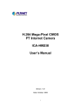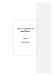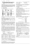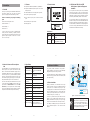
1
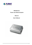
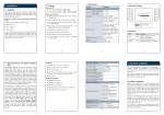
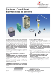
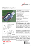
1.3 Features
1. Introduction
1.5 Product Outlook
2.2 POE-400 and POE-152S, the IEEE
802.3af Injector / Splitter and Equipment
Installation
uComplies with IEEE 802.3, IEEE 802.3u, 10/100Base-TX
uComplies with IEEE 802.3af, 48V DC power over unused
twisted-pair wires
1.1 Checklist
Thank you for purchasing our POE-400 IEEE 802.3af Power
over Ethernet Injector Hub, your Power over Ethernet
Injector Hub package shall contains following contents:
For the places hard to find the power inlet, the POE-400
provide the easiest way to power your Ethernet devices
such as PLANET IEEE 802.3af Power over Ethernet Splitter
(POE-152S) with Internet Camera (ICA-M220) or Wireless
Access Point (WNAP-3000PE) installed in the small office.
u4-Port IEEE 802.3af in-line mid-span power injector box
uFull power support for per POE port
Check the contents of your package for following
parts:
uCircuit protection prevent power interference between
ports
l Power over Ethernet Injector Hub x 1
uLED indicator power input indication
l User’s Manual CD x 1
uDesktop palm size
To control the power system of your networking devices, the
POE-400 can directly co-work with PLANET ICA-HM230 and
POE IP Phone VIP-351PT to build VoIP telephony network in
the office. Besides, the POE-400 can be directly deployed to
connect the third party IEEE 802.3af devices like Cisco AP
and POE switches installed 100 meters away.
l Power Adapter x 1
l Power Cord x 1
If any of these pieces are missing or damaged, please
contact your dealer immediately, if possible, retain the
carton including the original packing material, and use them
against to repack the product in case there is a need to
return it to us for repair.
LED Definition:
-1-
1.2 About the Power over Ethernet Injector
Hub
The PLANET POE-400 is a 4-Port IEEE 802.3af Power over
Ethernet injector hub complied with IEEE 802.3, IEEE
802.3u and IEEE 802.3af standards. Equipped with 4
10/100Base-TX Fast Ethernet ports, the POE-400 supports
full 48V DC power for any remote IEEE 802.3af powered
device (PD) like Wireless LAN Access Point, IP Phone, and
LAN Camera. Supporting power supply of 70 Watts, POE400 provides sufficient power to the 4 remote devices.
There are 8 RJ-45 STP ports on POE-400. Half of the ports
on right panel function as "Data" and the other half on left
panel function as "Data and Power". Each of the "Data
and Power" port as an injector which inserts DC Voltage
into the CAT 5 cable allowing the cable between the Injector
and Splitter to transfer data and power simultaneously.
-3-
Ethernet Connector
Ethernet Data Rate
Input Voltage
POE-400
Function
Power
Green
Lights to indicate that the POE-400
has power.
PoE Ready /
In-Use
Green
Lights to indicate the port is
providing 48VDC in-line power.
This product provides two different running speeds –
10Mbps, 100Mbps, in the same device and automatically
distinguishes the speed of incoming connection.
10/100Mbps (vary on Ethernet
device attached)
This section describes the hardware features of POE-400.
Before connecting any network device to the POE-400, read
this chapter carefully.
DC 48V, 1.5A
-7-
2. Hardware Installation
8-Port RJ-45 STP with 4-Port
"Data" and 4-Port "Data and
Power"
Notebook
Internet Camera
POE-AP
PoE
PoE
POE-Splitter
PoE
PoE
POE-400
VoIP Phone
DC
Number of Device
can be Power
4
Ethernet Cable
TIA/EIA-568, Category 5/5e cable
LED Indicator
1 x power, 4 x POE ready / in-use
Operating
Environment
0~50 Degree C, 5%~90%RH
Storage Environment -10~70 Degree C, 5%~90%RH
Dimension
(H x W x D)
26 x 70 x 97mm
Weight
220g
Emission
FCC Class B, CE mark
IEEE 802.3 Ethernet
Standard Compliance IEEE 802.3u Fast Ethernet
IEEE 802.3af Power over Ethernet
-2-
Color
-5-
1.4 Specification
Model
LED
-4-
2.1.Before Installation
Before your installation, it is recommended to check your
network environment. If there is any IEEE 802.3af devices
need to power on, the POE-400 can provide you a way
to supply power for this Ethernet device conveniently and
easily. The POE-400 equips with an AC-DC adapter with
DC 48V input and injects this DC power into the pin of the
twisted pair cable (pair 4, 5 and pair 7, 8).
Switch
Internet Camera
PC
-6-
PC
PC
100Base-TX UTP
PoE
100Base-TX UTP with PoE
DC
Power Line (DC)
Figure 1: Connection architecture over POE-400
If there is very difficult to find a power socket for AC-DC
Adapter of your non-IEEE 802.3af networked device, the
POE-400 and POE-152S can provide you a way to supply
DC power for this Ethernet device conveniently and easily.
The 10Mbps or 100Mbps speed, duplex mode from Data
port of POE-400 depends on which Ethernet device
attached.
PC
Note
1. According to IEEE 802.3af standard, the
POE-400 will not inject power to the cable
if not connecting to IEEE 802.3af devices.
2. Due to the capability of IEEE 802.3af
standard, the POE-400 can directly connect
with any IEEE 802.3af end-nodes.
-8-
3. Troubleshooting
This chapter contains information to help you solve
problems. If the PoE Injector Hub is not functioning
properly, make sure the PoE Injector Hub was set up
according to instructions in this manual.
Appendix A Networking Connection
Switch's RJ-45 Pin Assignments
10/100Mbps, 10/100Base-TX
RJ-45 Connector pin assignment
Contact
MDI
Media Dependant
Interface
MDI-X
Media Dependant
Interface -Cross
Solution:
1
Tx + (transmit)
Rx + (receive)
You can use PLANET Power over Ethernet Splitter, such as
PLANET POE-152S to work as a power transformer between
POE-400 and non IEEE 802.3af devices. Two types of POE152S are available for different voltage, 5V DC and 12V DC.
2
Tx - (transmit)
Rx - (receive)
3
Rx + (receive)
Tx + (transmit)
How to let my non IEEE 802.3af network devices
can work with POE-400?
4, 5
IEEE 802.3af DC 48V
6
The PoE LED is not lit
Rx - (receive)
7, 8
Tx - (transmit)
IEEE 802.3af DC 0V
Solution:
Check the cable connection between POE-400 and IEEE
802.3af device.
-9-
Why I connect my PoE device to POE-400 and it
cannot power on?
Solution:
1.Please check the cable type of the connection from POE400 to the other end. The cable should be an 8-wire UTP,
Category 5/5e, EIA568 cable within 100 meters. A cable
with only 4-wire, short loop or over 100 meters, all will
affect the power supply.
2.Please check and assure the device that fully complied
with IEEE 802.3af standard.
- 11 -
The standard RJ-45 receptacle/connector
There are 8 wires on a standard UTP/STP cable and each
wire is color-coded. The following shows the pin allocation
and color of straight cable and crossover cable connection:
Straight Cable
1 2 3 4 5 6 7 8
SIDE 1
1 2 3 4 5 6 7 8
SIDE 2
SIDE 1
SIDE 2
1 = White/Orange
2 = Orange
3 = White/Green
4 = Blue
5 = White/Blue
6 = Green
7 = White/Brown
8 = Brown
1 = White/Orange
2 = Orange
3 = White/Green
4 = Blue
5 = White/Blue
6 = Green
7 = White/Brown
8 = Brown
Cross Over Cable
1 2 3 4 5 6 7 8 SIDE 1
1 2 3 4 5 6 7 8 SIDE 2
SIDE 1
SIDE 2
1 = White/Orange
2 = Orange
3 = White/Green
4 = Blue
5 = White/Blue
6 = Green
7 = White/Brown
8 = Brown
1 = White/Green
2 = Green
3 = White/Orange
4 = Blue
5 = White/Blue
6 = Orange
7 = White/Brown
8 = Brown
Energy Saving Note of the Device
This power required device does not support Standby mode
operation.
For energy saving, please remove the power cable to
disconnect the device from the power circuit.
Without removing power cable, the device will still
consuming power from the power source. In the view of
Saving the Energy and reduce the unnecessary power
consuming, it is strongly suggested to remove the power
connection for the device if this device is not intended to be
active.
Figure A-1: Straight-Through and Crossover Cable
Please make sure your connected cables are with same pin
assignment and color as above picture before deploying the
cables into your network.
- 10 -
- 12 -
- 13 -
- 14 -