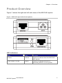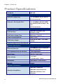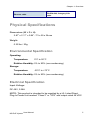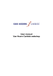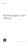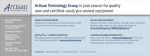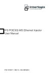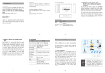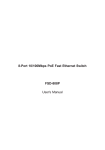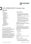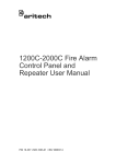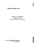
1
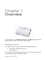
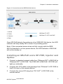
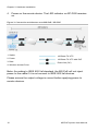
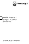
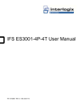
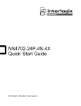
IFS MS-PoE Injector User Manual P/N 1069179-EN • REV 1.01 • ISS 14JUL10 Copyright © 2011 UTC Fire & Security. All rights reserved. This document may not be copied in whole or in part or otherwise reproduced without prior written consent from UTC Fire & Security, except where specifically permitted under US and international copyright law. Disclaimer The information in this document is subject to change without notice. UTC Fire & Security assumes no responsibility for inaccuracies or omissions and specifically disclaims any liabilities, losses, or risks, personal or otherwise, incurred as a consequence, directly or indirectly, of the use or application of any of the contents of this document. For the latest documentation, contact your local supplier or visit us online at www.interlogix.com. This publication may contain examples of screen captures and reports used in daily operations. Examples may include fictitious names of individuals and companies. Any similarity to names and addresses of actual businesses or persons is entirely coincidental. Trademarks and patents The Interlogix name and logo are trademarks of UTC Fire & Security. The IFS name and logo are trademarks of UTC Fire & Security. Other trade names used in this document may be trademarks or registered trademarks of the manufacturers or vendors of the respective products. Intended use Use this product only for the purpose it was designed for; refer to the data sheet and user documentation for details. For the latest product information, contact your local supplier or visit us online at www.interlogix.com. Manufacturer UTC Fire & Security Americas Corporation, Inc. 2955 Red Hill Avenue Costa Mesa, CA 92626-5923, USA EU authorized manufacturing representative: UTC Fire & Security B.V., Kelvinstraat 7, 6003 DH Weert, The Netherlands Certification MS-PoE Injector User Manual N4131 i FCC compliance This equipment has been tested and found to comply with the limits for a Class B digital device, pursuant to part 15 of the FCC Rules. These limits are designed to provide reasonable protection against harmful interference in a residential installation. This equipment generates, uses and can radiate radio frequency energy and, if not installed and used in accordance with the instructions, may cause harmful interference to radio communications. However, there is no guarantee that interference will not occur in a particular installation. If this equipment does cause harmful interference to radio or television reception, which can be determined by turning the equipment off and on, the user is encouraged to try to correct the interference by one or more of the following measures: • Reorient or relocate the receiving antenna. • Increase the separation between the equipment and receiver. • Connect the equipment into an outlet on a circuit different from that to which the receiver is connected. • Consult the dealer or an experienced radio/TV technician for help. ACMA compliance Canada Notice! This is a Class A product. In a domestic environment this product may cause radio interference in which case the user may be required to take adequate measures. This Class A digital apparatus complies with Canadian ICES‐003. Cet appareil numérique de la classe A est conforme á la norme NMB‐ 003du Canada. European Union directives Contact information ii 2004/108/EC (EMC Directive): Hereby, UTC Fire & Security declares that this device is in compliance with the essential requirements and other relevant provisions of Directive 2004/108/EC. 2002/96/EC (WEEE directive): Products marked with this symbol cannot be disposed of as unsorted municipal waste in the European Union. For proper recycling, return this product to your local supplier upon the purchase of equivalent new equipment, or dispose of it at designated collection points. For more information see: www.recyclethis.info. For contact information see our Web site: www.interlogix.com. MS-PoE Injector User Manual Content Chapter 1 Overview 1 Introduction 2 Product Overview 3 Product Specifications 4 Physical Specifications 5 Chapter 2 Hardware Installation 7 Before Installation 7 Installing the MS-PoE 8 MS-PoE Injector User Manual iii Chapter 1 Overview The IFS MS-PoE is an IEEE 802.3af Power over Ethernet Injector that provides 48VDC power over Ethernet cables (PoE). Package Contents Your MS-PoE injector carton should contain the following items: The Power over Ethernet Injector x 1 Users Manual x 1 If any item is missing or damaged, please consult the dealer from whom you purchased you MS-PoE injector module. MS-PoE Injector User Manual 1 Chapter 1: Overview Introduction The IFS MS-PoE IEEE 802.3af Power over Ethernet Injector inserts DC Voltage into Cat.5 cable, allowing the cable between the Injector (MSPoE) and Splitter (SP-PoE) to transfer data and power simultaneously. The maximum distance between the Injector (MS-PoE) and Splitter (SPPoE) is 100 meters. With MS-PoE installed, it combines the Ethernet digital data with power over the twisted pair cables as an IEEE 802.3af Power over Ethernet Injector. The IEEE 802.3af Power over Ethernet splitter can separate the digital data and power into two outputs. With IEEE 802.3af Power over Ethernet devices installed, the system administrator only has to use a single RJ-45 Ethernet cable to carry both power and data to each device. Product Features 2 Complies with IEEE 802.3af Power over Ethernet, IEEE 802.3/802.3u 10/100Base-TX Provide DC 48V power over RJ-45 Ethernet cable to device with Ethernet port LED indicators power input indication Distance up to 100 meters Auto-detect of PoE IEEE 802.3af equipment, protects devices from being damaged by an incorrect installation Work with EIA568, category 5,4-pair cables for 10Base-T or 100Base-TX EMI standards comply with FCC, CE class B Saves time and reduces installation costs Easy plug-and-play installation. MS-PoE Injector User Manual Chapter 1: Overview Product Overview Figure 1 shows the right and left side views of the MS-PoE injector. Figure 1: MS-PoE right and left side panels LED Indicators LED Color Function Power Yellow Lights to indicate that the MS-PoE has power. PoE ready / in-use Green Lights to indicate the port is providing 48VDC in-line power. MS-PoE Injector User Manual 3 Chapter 1: Overview Product Specifications IFS Model MS-PoE Interface Ethernet Copper Port 1 x 10/100Base-TX for data in RJ-45 connector Ethernet + DC Copper Port 1 x 10/100Base-TX with IEEE 802.3af PoE PSE for data + DC out RJ-45 connector Power over Ethernet PoE Standard IEEE 802.3af Power over Ethernet / PSE PoE Power Supply Type Mid-Span / Type B Power PIN Assignment 4/5(+), 7/8(-) PoE Power Output PoE 48V DC, Max. 15.4 watts, 350mA Number of device can be powered 1 Hardware Specification Ethernet Data rate 10/100Mbps( vary on Ethernet device attached) Throughput(Packet per second) 148810@64Bytes Input Power 48V DC, 0.38A max. 1 x Power LED indicator 1 x PoE ready / in-use Installation Standalone or wall mount Material Plastic Standard Conformance IEEE 802.3 Ethernet Standard Compliance IEEE 802.3u Fast Ethernet IEEE 802.3af Power over Ethernet 4 MS-PoE Injector User Manual Chapter 1: Overview TIA/EIA-568, Category 5/5e cable Ethernet cable Physical Specifications Dimensions (W × D × H): 2.87” x 2.17” x 0.94” / 73 x 55 x 24mm Weight: 0.22 lbs / 50g Environmental Specification Operating: Temperature: 0°C to 50°C Relative Humidity: 5% to 90% (non-condensing) Storage: Temperature: -20°C to +70°C Relative Humidity: 5% to 90% (non-condensing) Electrical Specification Input Voltage: DC 48V, 0.38A NOTE: This product is intended to be supplied by a UL Listed Direct Plug-In Power Unit marked "Class 2" or "LPS" and output rated 48 VDC. MS-PoE Injector User Manual 5 Chapter 1: Overview 6 MS-PoE Injector User Manual Chapter 2 Hardware Installation This product provides two different running speeds - 10Mbps, 100Mbps in the same device and automatically distinguishes the speed of the incoming connection. This section describes the hardware installation of MS-PoE. Before connecting any network device to the MS-PoE, read this section carefully. Before Installation Before your installation, it is recommended that you check your network environment. If there are any IEEE 802.3af devices that you need to power, the MS-PoE can provide you a way to supply power for this Ethernet device conveniently and easily. The MS-PoE works with an ACDC adapter (not supplied) with DC 48V input and injects this DC power into the pin of the twisted pair cable (pair 4, 5 and pair 7, 8 for Fast Ethernet). MS-PoE Injector User Manual 7 Chapter 2: Hardware Installation If it is very difficult to find a power socket for an AC-DC Adapter of your non-IEEE 802.3af networked device, the MS-PoE and SP-POE can provide you a way to supply DC power for this Ethernet device conveniently and easily. Note: The MS-PoE and SP-POE can be installed in pair.s However, the use of third-party device is allowed if the device complies with IEEE 802.3af standard. Installing the MS-PoE 1. Connect a standard network cable from Switch/workstation to "Ethernet" port of MS-PoE. 2. Connect the long cable that will be used to connect to the remote device to the port "Ethernet + DC". 3. Connect an AC adapter to "DC 48V" of MS-PoE. The power LED will be steady on. Note: This product is intended to be supplied by a UL Listed Direct Plug-In Power Unit marked "Class 2" or "LPS" and output rated 48 VDC. 4. Connect to IEEE 802.3af devices. Due to the the IEEE 802.3af standard, the MS-PoE can directly connect with any IEEE 802.3af end-nodes such as a wireless access point, VoIP phones and Internet cameras which support IEEE 802.3af In-line Power over Ethernet port. 8 MS-PoE Injector User Manual Chapter 2: Hardware Installation Figure 2: Connection to the IEEE 802.3af device 1. Switch 2. Power 3. Camera 100 Base-TX UTP 100 Base-TX UTP with PoE 4. Data Once MS-PoE detects the existence of an IEEE 802.3af device, the LED indicator will stay steady ON to show it is providing power. Note: If the connected device does not fully comply with the IEEE 802.3af standard or in-line power device, the LED indicator of MS-PoE will not be steady on. Installing an MS-PoE and a SP-POE, Injector and Splitter 1. Connect a standard network cable from "Ethernet+DC" of MS-PoE to "Ethernet+DC" of SP-POE. The POE LED of MS-PoE / SP-POE will light up continually. 2. Connect the UTP cable in the package from "Ethernet" of SP-POE to the RJ-45 port of the remote device. 3. Connect the correct DC plug from "DC OUT" of SP-POE to the remote device. MS-PoE Injector User Manual 9 Chapter 2: Hardware Installation 4. Power on the remote device. The LED indicator on SP-POE remains on. Figure 3: Connection architecture over MS-PoE / SP-POE 1. Switch 100 Base-TX UTP 2. Power 100 Base-TX UTP with PoE 3. Data Power line (DC) 4. Wireless Access Point Note: According to IEEE 802.3af standard, the MS-PoE will not inject power to the cable if it is not connect to IEEE 802.3af devices. Please ensure the output voltage is correct before applying power to remote devices. 10 MS-PoE Injector User Manual