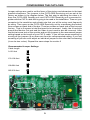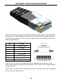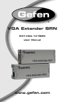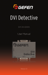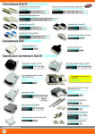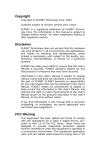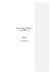
1
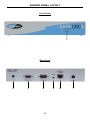
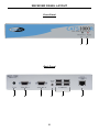
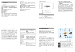
CAT5·1000
EXT-CAT5-1000
User Manual
www.gefen.com
f
ASKING FOR ASSISTANCE
Technical Support:
Telephone
(818) 772-9100
(800) 545-6900
Fax
(818) 772-9120
Technical Support Hours:
8:00 AM to 5:00 PM Monday thru Friday.
Write To:
Gefen Inc.
c/o Customer Service
20600 Nordhoff St
Chatsworth, CA 91311
www.gefen.com
[email protected]
Notice
Gefen Inc. reserves the right to make changes in the hardware, packaging and
any accompanying documentation without prior written notice.
CAT5•1000 is a trademark of Gefen Inc.
© 2008 Gefen Inc., All Rights Reserved
All trademarks are the property of their respective companies
CONTENTS
1
Introduction
2
Operation Notes
3
Features
4
Sender Panel Layout
5
Sender Panel Descriptions
6
Receiver Panel Layout
7
Receiver Panel Descriptions
8
Connecting And Operating The CAT5•1000
9
Configuring The CAT5•1000
10 Specifications
11 Warranty
INTRODUCTION
Congratulations on your purchase of the CAT5•1000. Your complete satisfaction
is very important to us.
Gefen
Gefen delivers innovative, progressive computer and electronics add-on solutions
that harness integration, extension, distribution and conversion technologies.
Gefen’s reliable, plug-and-play products supplement cross-platform computer
systems, professional audio/video environments and HDTV systems of all sizes
with hard-working solutions that are easy to implement and simple to operate.
The Gefen CAT5•1000
The CAT5-1000 requires just one CAT5 cable to transmit video, audio and control
signals to the remote workstation. It essentially bundles the signals together
before, during and after transmission so that cabling is reduced while reliable
signal transmission is achieved. This is the ideal solution for anyone who desires
an effective method to extend their workstation anywhere within 330-feet from the
computer
The CAT5-1000 and the CAT5-1500 work with all CRT and LCD computer
monitors as well as USB-equipped keyboards and mice (Mac or PC).
How It Works
Both the CAT5-1000 and the CAT5-1500 utilize a sender and receiver
methodology to connect the extended workstation to the computer. Simply
connect the sender unit to your computer using the cables provided. Then
connect the receiver unit to the computer?s keyboard, monitor and mouse at the
remote location. CAT5 cable(s), sold separately, then connect the sender unit to
the receiver unit. Both the sender and the receiver units must be connected to
a power supply. When fully powered and operational, the units efficiently extend
video, audio and control signals.
1
OPERATION NOTES
READ THESE NOTES BEFORE INSTALLING OR
OPERATING THE CAT5•1000
•
The CAT5•1000 will extend analog VGA video, analog 2 channel stereo
audio, and USB up to 330 feet.
•
Supports resolutions up to 1920 x 1200.
•
USB 1.1 compliant.
•
Audio extension is designed for line-out audio sources only. Amplified audio
is not supported and may damage the CAT5•1000.
•
Single CAT-5 extension should be terminated according to the TIA/EIA568-B specification. Please see page ## for details.
•
The use of patch panels, couplers, and splices are not recommended as
these may degrade the signal and produce unexpected results.
•
Display information (EDID) is not transmitted from the display back to the
source. Standard VESA resolutions should pass without issue, but wide
screen resolutions and non-standard VESA resolutions may not be listed for
selection by the source. In this case, the source must either be able to force
the output of the desired resolution or a EDID storage device (part# EXTDVI-EDIDN) must be used to record the displays information. This device
must be placed before the CAT5•1000 sender unit and must be the first
device after the computer in the extension chain.
2
FEATURES
Features
•
Extends any VGA display up to 330 feet (100 meters)
•
Maintains 1920 x 1200 resolution video
•
Extends USB 1.1 compliant devices up to 330 feet
•
Audio is extended for multimedia applications
•
Uses one CAT-5e cable
•
Rack mountable
Package Includes
(1) CAT5•1000 Sender Unit
(1) CAT5•1000 Receiver Unit
(1) 6 Foot VGA Cable (PC/Black)
(1) 6 Foot USB A to B Cable
(1) 6 Foot Audio Cable
(1) 5V DC Power Adapters
3
SENDER PANEL LAYOUT
Front Panel
1
Back Panel
2
3
4
5
4
6
7
SENDER PANEL DESCRIPTIONS
1
Power LED
This LED will become active once the included 5V DC power adapter is properly
connected.
2
5V DC Power Connector
Connect the included 5V DC power adapter to this connection port.
3
Local Monitor Output Port
Use this port to connect an local VGA monitor for monitoring purposes. This is
useful if both local and extended locations need to view the VGA source.
4
VGA Input
Connect the VGA source to this input.
5
Stereo Analog Audio Input
Connect a stereo analog mini-jack audio source to this input.
6
RJ-45 Input Port
Connect an CAT-5 cable to this port to connect the sending and receiving units
together.
7
USB B Input
Connects the computer’s USB to the CAT5•1000. The input on the CAT5•1000
is USB B while the computer will need a USB A cable input. A USB B to A
cable is provided with the CAT5•1000.
5
RECEIVER PANEL LAYOUT
Front Panel
1
Back Panel
3
4
5
6
6
7
8
2
RECEIVER PANEL DESCRIPTIONS
1
Brightness Adjustment
The Trim Pot is used for adjusting the brightness of the output video. If the
image is too bright or too dark, adjust this setting until the desired brightness is
reached.
2
Power LED
This LED will become active once the included 5V DC power adapter is properly
connected.
3
5V DC Power Connector
Connect the included 5V DC power adapter to this connection port.
4
VGA 1 Output Port
This is the first of two VGA output ports. This output will mirror the input video
signal from the VGA source. Output from VGA Output 2 will be the same at this
output port.
5
VGA 2 Output Port
This is the second of two VGA output ports. This output will mirror the input
video signal from the VGA source. Output from VGA Output 1 will be the same
at this output port.
6
Stereo Analog Audio Output
Connect a stereo analog mini-jack audio device to this output.
7
USB A Output
Connect USB peripherals to these output ports (4 are provided). Connected
devices will essentially be connected to the local computer from their remote
location.
8
RJ-45 Input Port
Connect an CAT-5 cable to this port to connect the sending and receiving units
together.
7
CONNECTING AND OPERATING THE CAT5•1000
How to Connect the CAT5•1000
1.
Connect the VGA source to the CAT5•1000 Sending unit using the supplied
VGA cable. Optionally connect a local monitor to the local monitor output on
the CAT5•1000 Sending unit.
2.
Connect the computer’s USB to the CAT5•1000 Sending unit using the
supplied USB A to B cable.
3.
Connect the computer’s audio to the CAT5•1000 Sending unit using the
supplied analog stereo audio mini-jack cable.
4.
Connect the CAT5•1000 Sending unit to the CAT5•1000 Receiving unit using
one user supplied CAT-5 cable.
5.
Connect the output display(s) at the remote location to the CAT5•1000
Receiving unit. Up to 2 displays can be connected using both VGA output
ports. Both outputs are identical and will mirror the VGA input source from
the CAT5•1000 Sender.
6.
Connect the USB peripherals to the CAT5•1000 Receiving unit using user or
device supplied USB cables.
7.
Connect amplified speakers to the CAT5•1000 Receiving unit’s analog
stereo mini-jack port using a user or device supplied audio cable.
8.
Connect the included 5V DC power adapters to both the CAT5•1000
Sending and Receiving units.
9.
Power on the display and then the source.
NOTE: Display information (EDID) is not transmitted from the display back to the
source. Standard VESA resolutions should pass without issue, but wide screen
resolutions and non-standard VESA resolutions may not be listed for selection
by the source. In this case, the source must either be able to force the output of
the desired resolution or a EDID storage device (part# EXT-DVI-EDIDN) must
be used to record the displays information. This device must be placed before
the CAT5•1000 sender unit and must be the first device after the computer in the
extension chain.
8
CONFIGURING THE CAT5•1000
Jumper settings are used to set the focus of the picture and characters to the best
possible sharpness. The jumpers in the CAT5•1000 Receiving unit are set at the
factory as shown in the diagram below. The first step to adjusting the video is to
have the CAT5•1000 Sending unit and CAT5•1000 Receiving unit connected together with the CAT-5 cable that is going to be used in the installation. Then set your
computer to the resolution and refresh rate that you will be using most frequently
be using. Then open up the CAT5•1000 Receiving unit by unscrewing the bottom
three screws on back end of the box. Then two screws on each side of the box and
the top. That is 9 screws in total that need to be removed. Lastly, the 4 hex bolts
around the Monitor Out port and the Video In port need to also be removed. After
that look at some text on the monitor and set the jumpers to the recommend jumper
setting based on the length of your CAT-5 cable. If you still see some smearing try
moving all the jumpers up or down one from the recommended setting. If you see
smearing of just one color adjust an individual jumper for the color that is smearing
(it can be two colors). Repeat the same steps for monitor 2
Recommended Jumper Settings
Cable length
0-132 feet
133-198 feet
199-264 feet
265-330 feet
9
NETWORK CABLE WIRING DIAGRAM
Gefen has specifically engineered their products to work with the TIA/EIA-568-B
specification. Please adhere to the table below when field terminating cable for
use with Gefen products. Failure to do so may produce unexpected results and
reduced performance.
Pin
Color
1
Orange / White
2
Orange
3
Green / White
4
Blue
5
Blue / White
6
Green
7
Brown / White
8
Brown
12345678
CAT-5, CAT-5e, and CAT-6 cabling comes in stranded and solid core types.
Gefen recommends using solid core cabling. CAT-6 cable is also recommended
for best results.
Each cable run must be one continuous run from one end to the other. No splices
or use of punch down blocks.
10
SPECIFICATIONS
Video Amplifier Bandwidth ....................................................................... 350 MHz
Actual Bandwidth ..................................................................................... 120 MHz
Input Video Signal .............................................................................. 1.2 Volts p-p
Input Sync Signal ........................................................................ 5 Volts p-p (TTL)
Horizontal Frequency Range ................................................................ 15-70 KHz
Vertical Frequency Range ................................................................... 30 - 170 Hz
Video In......................................................................................................... HD-15
Focus/Brightness Control .................................................................. 25 to 450 FT
Video out ...................................................................................................... HD-15
Link Connector ............................................................................................. RJ-45
USB - “A” Connector .............................................................................. USB Input
USB - “B” Connector .................................................................. USB Device Input
Power Consumption ...................................................................... 15 Watts (max.)
Power Supply .............................................................................. 5 VDC (External)
Dimensions ....................................................................... 1.75”H x 8.4”W x 4.6”D
Rack Mountable ............................................................................. 1 Rack Spaces
Shipping Weight ............................................................................................ 8 Lbs
11