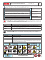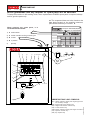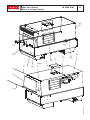
1
GE 20000 LS/GS
0608
250209003 - GB
USE AND MAINTENANCE MANUAL
SPARE PARTS CATALOG
17/09/07 25020M00
preparato da UPT
approvato da DITE
M
Quality system
© MOSA
GE_, MS_, TS_, EAS_
01
1.2-05/03
UNI EN ISO 9001 : 2000
MOSA has certified its quality system according to
UNI EN ISO 9001:2000 to ensure a constant, high
quality of its products. This certification covers the
design, production and servicing of engine driven
welders and generating sets.
The advantages for MOSA clients are:
The certifying institute, ICIM, which is a member of
the International Certification Network IQNet,
awarded the official approval to MOSA after an
examination of its operations at the head office and
plant in Cusago (MI), Italy.
· Competent support in the solution of problems;
· Continuous efforts to improve the products and
their performance at competitive conditions;
· Information and training in the correct application
and use of the products to assure the security of
the operator and protect the environment;
· Regular inspections by ICIM to confirm that the
requirements of the company’s quality system
and ISO 9001 are being respected.
All these advantages are guaranteed by the
CERTIFICATE OF QUALITY SYSTEM No.0192
issued by ICIM S.p.A. - Milano (Italy ) - www.icim.it
10/10/02 M01-GB
This certification is not a point of arrival but a pledge
on the part of the entire company to maintain a level
of quality of both its products and services which
will continue to satisfy the needs of its clients, as
well as to improve the transparency and the
communications regarding all the company’s actives
in accordance with the official procedures and in
harmony with the MOSA Manual of Quality.
· Constant quality of products and services at the
high level which the client expects;
INDEX
M
1
REV.1-10/07
M 01
M 1.01
M 1.1
M 1.4
M 1.5
M 1.6
M 2-2.1
M 2.5...
M 2.6
M 2.7
M3
M 4...
M 6...
M 20
M 21
M 22
M 25
M 26
M 27
M 30
M 31
M 34
M 35
M 36
M 37...
M 38...
M 39...
M 40...
M 43...
M 45
M 46
M 53
M 55
M 60
M 61...
QUALITY SYSTEM
COPYRIGHT
NOTES
CE MARK
TECHNICAL DATA
TECHNICAL DATA ENGINE DRIVEN WELDER
SYMBOLS AND SAFETY PRECAUTIONS
INSTALLATION AND ADVICE BEFORE USE
INSTALLATIONS AND ADVICE
INSTALLATION
PACKING
TRANSPORT AND DISPLACEMENTS
ASSEMBLY: CT........
SETTING-UP THE UNIT (DIESEL ENGINE)
ENGINE STARTING AND USE (DIESEL ENGINE)
STOPPING THE ENGINE (DIESEL ENGINE)
SETTING-UP THE UNIT (GASOLINE ENGINE)
STARTING THE ENGINE (GASOLINE ENGINE)
STOPPING THE ENGINE (GASOLINE ENGINE)
CONTROLS LEGEND
CONTROLS
USE AS A WELDER
USE AS AN ENGINE STARTER
USE AS A BATTERY CHARGE
USE AS A GENERATOR
USE OF THE REMOTE CONTROL
USE OF THE ENGINE PROTECTION
TROUBLE SHOOTING
MAINTENANCE
STORAGE
CAST OFF
DIMENSIONS
RECOMMENDED ELECTRODES
ELECTRICAL SYSTEM LEGENDE
ELECTRICAL SYSTEM
R1
......
SPARE PARTS LIST
SPARE PARTS
K...
ACCESSORIES
11/01/01 M1-GB
© MOSA
GE_, MS_, TS_, EAS_
Copyright
© MOSA
GE_, MS_, TS_, EAS
M
1.01
1.0-10/02
ATTENTION
This use and maintenance manual is an important
part of the machines in question.
The assistance and maintenance personel must
keep said manual at disposal, as well as that for
the engine and alternator (if the machine is
synchronous) and all other documentation about the
machine.
We advise you to pay attention to the pages
concerning the security (see page M1.1).
© All
rights are reserved to said Company.
It is a property logo of MOSA division of B.C.S.
S.p.A. All other possible logos contained in the
documentation are registered by the respective
owners.
➠ The reproduction and total or partial use, in any
form and/or with any means, of the
documentation is allowed to nobody without a
written permission by MOSA division of B.C.S.
S.p.A.
To this aim is reminded the protection of the author’s
right and the rights connected to the creation and
design for communication, as provided by the laws
in force in the matter.
In no case MOSA division of B.C.S. S.p.A. will be
held responsible for any damaga, direct or indirect,
in relation with the use of the given information.
10/10/02 M1-01-GB
MOSA division of B.C.S. S.p.A. does not take any
responsibility about the shown information on firms
or individuals, but keeps the right to refuse services
or information publication which it judges discutible,
unright or illegal.
Notes
© MOSA
GE_, MS_, TS_, EAS_
M
1-1
1.0-10/02
INFORMATION
Dear Customer,
We wish to thank you for having bought from
MOSA a high quality set.
Our sections for Technical Service and Spare
Parts will work at best to help you if it were
necessary.
To this purpose we advise you, for all control and
overhaul operations, to turn to the nearest
authorized Service Centre, where you will obtain
a prompt and specialized intervention.
☞ In case you do not profit on these Services and
some parts are replaced, please ask and be
sure that are used exclusively original MOSA
parts; this to guarantee that the performances
and the initial safety prescribed by the norms in
force are re-established.
☞ The use of non original spare parts will cancel
immediately any guarantee and Technical Service obligation from MOSA.
NOTES ABOUT THE MANUAL
Before actioning the machine please read this
manual attentively. Follow the instructions
contained in it, in this way you will avoid
inconveniences due to negligence, mistakes or
incorrect maintenance. The manual is for qualified
personnel, who knows the rules: about safety and
health, installation and use of sets movable as
well as fixed.
INFORMATION OF GENERAL TYPE
In the envelope given together with the machine
and/or set you will find: the manual for Use
Maintenance and Spare Parts, the manual for
use of the engine and the tools (if included in the
equipment), the guarantee (in the countries where
it is prescribed by law).
Our products have been designed for the use of
generation for welding, electric and hydraulic
system; ANY OTHER DIFFERENT USE NOT
INCLUDED IN THE ONE INDICATED, relieves
MOSA from the risks which could happen or,
anyway, from that which was agreed when selling
the machine; MOSA excludes any responsibility
for damages to the machine, to the things or to
persons in this case.
Our products are made in conformity with the
safety norms in force, for which it is advisable to
use all these devices or information so that the
use does not bring damage to persons or things.
While working it is advisable to keep to the
personal safety norms in force in the countries to
which the product is destined (clothing, work tools,
etc.).
Do not modify for any motive parts of the machine
(fastenings, holes, electric or mechanical devices,
others..) if not duly authorized in writing by MOSA:
the responsibility coming from any potential
intervention will fall on the executioner as in fact
he becomes maker of the machine.
You must remember that, in case you have
difficulties for use or installation or others, our
Technical Service is always at your disposal for
explanations or interventions.
You must take into account that some figures
contained in it want only to identify the described
parts and therefore might not correspond to the
machine in your possession.
☞
Notice: this manual does not engage MOSA,
who keeps the faculty, apart the essential
characteristics of the model here described and
illustrated, to bring betterments and modifications
to parts and accessories, without putting this
manual uptodate immediately.
10/10/02 M 1-1 GB
The manual for Use Maintenance and Spare Parts
is an integrant part of the product. It must be kept
with care during all the life of the product.
In case the machine and/or the set should be
yielded to another user, this manual must also
given to him.
Do not damage it, do not take parts away, do not
tear pages and keep it in places protected from
dampness and heat.
M
1.4
CE MARK
© MOSA
REV.4-10/07
Any of our product is labelled with CE marking attesting its conformity to appliable directives
and also the fulfillment of safety requirements of the product itself; the list of these directives is
part of the declaration of conformity included in any machine standard equipment.
Here below the adopted symbol:
CE marking is clearly readable and unerasable and it can be either part of the data-plate (A) or
placed as a sticker near the data-plate (B)
A
B
The indication is shown in a clear, readable and indeleble way on a sticker.
10/10/02 M1-4 GB
Furthermore, on each model it is shown the noise level value; the symbol used is the following:
Technical data
© MOSA
GE 20000 LS/GS
M
1.5
REV.1-06/08
The generating set GE 20000 is a unit which transforms the mechanical energy, generated by endothermic engine, into electric
energy, through an alternator.
Is meant for industrial and professional use, powered by an endothermic engine; it is composed of various main parts such as:
engine, alternator, electric and electronic controls, the fairing or a protective structure.
The assembling is made on a steel structure, on which are provided elastic support which must damp the vibrations and also
eliminate sounds which would produce noise.
Technical data
GE 20000 LS/GS
A.C. GENERATOR
Three-phase generation (stand-by)
Single-phase generation (P.R.P.)
Single-phase generation
Service
Insulating class
ALTERNATOR
18 kVA (14.4 kW)/ 400 V / 26 A
16 kVA (12.8 kW)/ 230 V / 23 A
9 kVA / 230 V / 39.1 A
100 %
H
self-excited, self-regulated, with brush
Type
Frequency
ENGINE
synchronous, threephase
50 Hz
Mark / Model
Type / Cooling system
Cylinders / Displacement
Output
Speed
Fuel / Fuel consumption
Engine oil capacity
Starter
GENERAL SPECIFICATIONS
Lombardini / 9LD625/2
4 Stroke / air
2 / 1250cm3
19.1 kW (26 HP)
3000 rpm
Diesel / 250 g/kWh
2.8 l
Electric
Battery
Tank capacity
Running time (75%)
Protection
Dimensions/ max. (Lxlxh in mm) *
Weight on base
Noise level
12V 60Ah
26 l
7.5 h
IP 23
1456x841x880
386 Kg
99 LWA (74 dB(A) - 7 m)
* Dimensions and weight are inclusive of all parts
OUTPUT
Declared power according to ISO 8528-1 (temperature 25°C, 30% relative humidity, altitude 100 m above sea level).
(*Stand-by) = maximum available power for use at variable loads for a yearly number of hours limited at 500 h. No overload is
admitted.
(**Prime power P.R.P.) = maximum available power for use at variable loads for a yearly illimited number of hours. The average
power to be taken during a period of 24 h must not be over 80% of the P.R.P.
It’s admitted overload of 10% each hour every 12 h.
In an approximative way one reduces: of 1% every 100 m altitude and of 2.5% for every 5°C above 25°C.
Lp a 1 meter = 95 dB(A) - 8 dB(A) = 87 dB(A)
Lp a 4 meters = 95 dB(A) - 20 dB(A) = 75 dB(A)
Lp a 7 meters = 95 dB(A) - 25 dB(A) = 70 dB(A)
Lp a 10 meters = 95 dB(A) - 28 dB(A) = 67 dB(A)
PLEASE NOTE: the symbol
when with acoustic noise values, indicates that the device respects noise emission limits
according to 2000/14/CE directive.
2000 / 14 / CE
17/09/07 25020-GB
ACOUSTIC POWER LEVEL
ATTENTION: The concrete risk due to the machine depends on the conditions in which it is used. Therefore, it is up to the enduser and under his direct responsibility to make a correct evaluation of the same risk and to adopt specific precautions (for
instance, adopting a I.P.D. -Individual Protection Device)
Acoustic Noise Level (LWA) - Measure Unit dB(A): it stands for acoustic noise released in a certain delay of time. This is not
submitted to the distance of measurement.
Acoustic Pressure (Lp) - Measure Unit dB(A): it measures the pressure originated by sound waves emission. Its value
changes in proportion to the distance of measurement.
The here below table shows examples of acoustic pressure (Lp) at different distances from a machine with Acoustic Noise
Level (LWA) of 95 dB(A)
SYMBOLS AND SAFETY PRECAUTIONS
© MOSA
M
2
1.0-11/99
SYMBOLS IN THIS MANUAL
- The symbols used in this manual are designed to call
your attention to important aspects of the operation of
the machine as well as potential hazards and dangers
for persons and things.
IMPORTANT ADVICE
- Advice to the User about the safety:
☞
GE_, MS_, TS_
N.B.: The information contained in the manual can
be changed without notice.
Potential damages caused in relation to the use of
these instructions will not be considered because
these are only indicative.
Remember that the non observance of the
indications reported by us might cause damage to
persons or things.
It is understood, that local dispositions and/or laws
must be respected.
WARNING
Situations of danger - no harm to persons
or things
SAFETY PRECAUTIONS
DANGEROUS
This heading warns of an immediate danger for persons
as well for things. Not following the advice can result in
serious injury or death.
WARNING
This heading warns of situations which could result in
injury for persons or damage to things.
CAUTION
To this advice can appear a danger for persons as well as
for things, for which can appear situations bringing material damage to things.
IMPORTANT
NOTE
ATTENTION
These headings refer to information which will assis you
in the correct use of the machine and/or accessories.
Do not use without protective devices provided
Removing or disabling protective devices on the
machine is prohibited.
26/11/99 M2GB
Do not use the machine if it is not in good technical
condition
The machine must be in good working order before
being used. Defects, especially those which regard
the safety of the machine, must be repaired before
using the machine.
SYMBOLS AND SAFETY PRECAUTIONS
M
2-1
1.1-04/03
SYMBOLS (for all MOSA models)
PROHIBITIONS No harm for persons
Use only with safety clothing -
STOP - Read absolutely and be duly attentive
Read and pay due attention
GENERAL ADVICE - If the advice is not
respected damage can happen to persons or
things.
HIGH VOLTAGE - Attention High Voltage.There
can be parts in voltage, dangerous to touch.
The non observance of the advice implies life
danger.
FIRE - Danger of flame or fire. If the advice is
not respected fires can happen.
HEAT - Hot surfaces. If the advice is not
respected burns or damage to things can be
caused.
EXPLOSION - Explosive material or danger of
explosion. in general. If the advice is not
respected there can be explosions.
WATER - Danger of shortcircuit. If the advice
is not respected fires or damage to persons
can be caused.
SMOKING - The cigarette can cause fire or
explosion. If the advice is not respected fires
or explosions can be caused.
ACIDS - Danger of corrosion. If the advice is
not respected the acids can cause corrosions
with damage to persons or things.
It is compulsory to use the personal
protection means given in equipment.
Use only with safety clothing It is compulsory to use the personal protection
means given in equipment.
Use only with safety protections It is a must to use protection means suitable for
the different welding works.
Use with only safety material It is prohibited to use water to quench fires on
the electric machines.
Use only with non inserted voltage It is prohibited to make interventions before
having disinserted the voltage.
No smoking It is prohibited to smoke while filling the tank
with fuel.
No welding It is forbidden to weld in rooms containing
explosive gases.
ADVICE No harm for persons and things
Use only with safety tools, adapted to the specific
use It is advisable to use tools adapted to the various
maintenance works.
Use only with safety protections, specifically suitable
It is advisable to use protections suitable for
the different welding works.
Use only with safety protections It is advisable to use protections suitable
for the different daily checking works.
WRENCH - Use of the tools. If the advice is
not respected damage can be caused to things
and even to persons.
Use only with safety protections It is advisable to use all protections while
shifting the machine.
PRESSION - Danger of burns caused by the
expulsion of hot liquids under pressure.
Use only with safety protections It is advisable to use protections suitable for
the different daily checking works.and/or of
maintenance.
ACCES FORBIDDEN to non authorizad peaple.
26/11/99 M2-1GB
© MOSA
GE_, MS_, TS_
INSTALLATION AND ADVICE BEFORE USE
© MOSA
GE_, MS_, TS_
M
2-5
1.0-06/00
The installation and the general advice concerning the operations, are finalized to the correct use of the
machine, in the place where it is used as generator group and/or welder.
Stop engine when fueling
Do not touch electric devices if you
are barefoot or with wet clothes.
ENGINE
Unscrew the cap slowly to let out the fuel vapours.
Slowly unscrew the cooling liquid tap if the liquid must be topped up.
The vapor and the heated cooling liquid under pressure can burn face, eyes, skin.
Do not fill tank completely.
Wipe up spilled fuel before starting engine.
Shut off fuel of tank when moving machine (where it is assembled).
Avoid spilling fuel on hot engine.
Sparks may cause the explosion of battery vapours
CHECKING BOARD
Do not smoke, avoid flames, sparks or electric tools when fueling.
Always keep off leaning surfaces
during work operations
Static electricity can demage the
parts on the circuit.
An electric shock can kill
☞ FIRST AID. In case the operator shold be sprayed by accident, from corrosive liquids a/o hot toxic gas
or whatever event which may cause serious injuries or death, predispose the first aid in accordance with
the ruling labour accident standards or of local instructions.
Skin contact
Eyes contact
Ingestion
Suction of liquids from
lungs
Inhalation
Wash with water and soap
Irrigate with plenty of water, if the irritation persists contact a specialist
Do not induce vomit as to avoid the intake of vomit into the lungs, send for a doctor
If you suppose that vomit has entered the lungs (as in case of spontaneous vomit) take the
subject to the hospital with the utmost urgency
In case of exposure to high concentration of vapours take immediately to a non polluted zone
the person involved
☞ FIRE PREVENTION. In case the working zone,for whatsoever cause goes on fire with flames liable to
cause severe wounds or death, follow the first aid as described by the ruling norms or local ones.
WARNING
WARNING
CAUTION
THE MACHINE MUST NOT BE USED IN AREAS WITH
EXPLOSIVE ATMOSPHERE
10/06/00 M2-5I
Particular protection
Useful warnings
EXTINCTION MEANS
Carbonate anhydride (or carbon dioxyde) powder, foam, nebulized water
Avoid the use of water jets
Cover eventual shedding not on fire with foam or sand, use water jets to cool off the
surfaces close to the fire
Wear an autorespiratory mask when heavy smoke is present
Avoid, by appropriate means to have oil sprays over metallic hot surfaces or over electric
contacts (switches,plugs,etc.). In case of oil sprinkling from pressure circuits, keep in
mind that the inflamability point is very low.
DANGEROUS
Appropriated
Not to be used
Other indications
M
2.6
INSTALLATION AND ADVICE
© MOSA
REV.1-06/07
INSTALLATION AND ADVICE BEFORE USE
GASOLINE ENGINES
■ Use in open space, air swept or vent exhaust gases,
which contain the deathly carbone oxyde, far from
the work area.
Check that the air gets changed completely and the hot
air sent out does not come back inside the set so as to
cause a dangerous increase of the temperature.
1,5
m
DIESEL ENGINES
Use in open space, air swept or vent exhaust gases
far from the work area.
■
1,5
1,5
m
m
T
PU
T
O
UIC
AOR
STC
S
I
D
U
ASA
GH
EX
☞ Make sure that the machine does not move during
the work: block it possibly with tools and/or devices
made to this purpose.
MOVES OF THE MACHINE
At any move check that the engine is off, that there
are no connections with cables which impede the
moves.
☞
PLACE OF THE MACHINE
ATTENTION
POSITION
Place the machine on a level surface at a distance of at
least 1,5 m from buildings or other plants.
For a safer use from the operator DO NOT
fit the machine in locations with high risk of
flood.
Please do not use the machine in weather
conditions which are beyond IP protection
shown both in the data plate and on page
named "technical data" in this same manual.
26/11/99 M2-6GB
Maximum leaning of the machine (in case of dislevel)
REV.1-06/08
Luftzirkulation
Instalación
GE 20000 LS/GS
M
2.7
M1.4
M1.4 B
17/09/07 25020-I
© MOSA
Installazione
Installation
Installation
UNPACKING
M
3
1.1-02/04
NOTE
☞ Be sure that the lifting devices are: correctly mounted,
adequate for the weight of the machine with it’s
packaging, and conforms to local rules and regulations.
When receiving the goods make sure that the product has not suffered damage during the transport,
that there has not been rough handling or taking
away of parts contained inside the packing or in the
set.
In case you find damages, rough handling or absence of parts (envelopes, manuals, etc.), we advise you to inform immediately our Technical Service.
For eliminating the packing materials, the User
must keep to the norms in force in his country.
1) Take the machine (C) out of the shipment packing.
Take out of the envelope (A) the user’s manual (B).
2) Read: the user’s manual (B), the plates fixed on the
machine, the data plate.
30/03/00 M3GB
© MOSA
GE_, MS_, TS_
TRANSPORT AND DISPLACEMENTS COVERED UNITS
© MOSA
GE_, MS_, TS_
M
4
1.0-03/00
NOTE
In case you should transport or move the machine, keep to the instructions as per the figures.
Make the transportation when the machine has no petrol in its tank, no oil in the engine and and electrolyte in the
battery.
Be sure that the lifting devices are: correctly mounted, adequate for the weight of the machine with it’s packaging, and
conform to local rules and regulations.
Only authorized persons involved in the transport of the machine should be in the area of movement.
DO NOT LOAD OTHER PARTS WHICH CAN MODIFY WEIGHT AND BARICENTER POSITION.
IT IS STRICTLY FORBIDDEN TO DRAG THE MACHINE MANUALLY OR TOW IT BY ANY VEHICLE (model with no
CTL accessory).
If you did not keep to the instructions, you could damage the structure of the machine.
LIFT ONLY THE MACHINE
DANGER: LIFTING EYE IS NOT DESIGNED TO SUPPORT
ADDED WEIGHT OF ROAD TOW TRAILER
30/03/00 M4GB
DO NOT LIFT THE MACHINE AND TRAILER
CTL400
M
6.2
ASSEMBLY
© MOSA
1.0-03/00
ATTENTION
The CTL accessory cannot be removed from the machine and used separately (actioned manually or following
vehicles) for the transport of loads or anyway for used different from the machine movements.
TRAILERS
The machines provided for assembling the CTL accessory (slow towing trolley) can be towed up to a maximum speed
of 40 Kms/hour on asphalted surfaces.
Towing on public roads or turnpikes of any type IS EXCLUDED, because not in possesion of the requirements by
national and foreign traffic norms.
Nota: Lift the machine and assemble the parts as shown in the drawing
For assembling the generating set on the trolley CTL400
please keep to following instructions:
ATTENTION
Do not substitute the original tires with other types.
4S
4V
4L
4I
5
9
7
8
4
10/06/00 M6I
- Lift the generating set (by means of suitable hook).
- Slightly fix the jaw (3) of the parking foot to the bar
with the M10x20 screws, the M10 nuts and the
washers (so as to let the foot sprag go through.
3) - Split (unscrewing them) the two parts of the foot
(4S-4I) to be able later to assemble them on the jaw.
4) - Introduce into the jaw (3) the upper part (4S) of the
foot and screw again the lower part (4I), then tighten
the screws (4V) of the jaw to the towbar and block
momentaneously with the lever (4L) the whole foot.
5) - Assemble on the machine the towbar (5) complete
of foot with the M10x20 screws, nuts and washers
(see fig. page M6.2).
6) - Assemble the axle (7) to the base of the machine
(see fig. page M6.2) with the M 10x20 screws and
relative washers (two per part) so that their supports
coincide.
8) - Insert the wheel (9) on the axle then screw the self
blocking nuts (8).
9) - Pump the tyre (9) bringing the pressure to four atms.
10) - Lower the machine to the ground and place the
parking foot definitively (regulating at the best height).
3
1)
2)
TS_GE
Air cooled systems
Set-up for operation (Engine diesel)
© MOSA
M
20
1.1-09/05
BATTERY WITHOUT MAINTENANCE
Connect the cable + (positive)
to the pole + (positive) of the
battery (after having taken
away the protection), by
properly tightening the clamp.
Check the state of the battery
from the colour of the warning light which is in the
upper part.
- Green colour: battery OK
- Black colour: battery to be recharged
- White colour: battery to be replaced
DO NOT OPEN THE BATTERY.
LUBRICANT
RECOMMENDED OIL
MOSA recommends selecting AGIP engine oil.
Refer to the label on the motor for the recommended
products.
OIL BATH AIR FILTER
Fill the air filter using the same engine oil up to the
level indicated on the filter.
FUEL
ATTENTION
Do not smoke or use open flames during
refuelling operations, in order to avoid
explosions or fire hazards.
Fuel fumes are highly toxic; carry out
operations outdoors only, or in a wellventilated environment.
Avoid accidentally spilling fuel. Clean
any eventual leaks before starting up
motor.
Refill the tank with good quality diesel fuel, such as
automobile type diesel fuel, for example.
For further details on the type of diesel fuel to use,
see the motor operating manual supplied.
Do not fill the tank completely; leave a space of
approx. 10 mm between the fuel level and the wall
of the tank to allow for expansion.
REFUELLING AND CONTROL:
Carry out refuelling and controls with motor at level
position.
1. Remove the oil-fill tap (24)
2. Pour oil and replace the tap
3. Check the oil level using the dipstick (23); the oil
level must be comprised between the minimum
and maximum indicators.
ATTENTION
It is dangerous to fill the motor with too much oil,
as its combustion can provoke a sudden increase
in rotation speed.
DRY AIR FILTER
Check that the dry air filter is correctly installed and
that there are no leaks around the filter which could
lead to infiltrations of non-filtered air to the inside of
the motor.
GROUNDING CONNECTION
The grounding connection to an earthed installation
is obligatory for all models equipped with a
differential switch (circuit breaker). In these groups
the generator star point is generally connected to
the machine’s earthing; by employing the TN or TT
distribution system, the differential switch
guarantees protection against indirect contacts.
In the case of powering complex installations
requiring or employing additional electrical protection
devices, the coordination between the protection
devices must be verified.
For the grounding connection, use the terminal
(12); comply to local and/or current regulations in
force for electrical installations and safety.
16/07/03 M20-R-A-GB
Please refer to the motor operating manual for the
recommended viscosity.
In rigid environmental temperature conditions, use
special winterized diesel fuels or specific additives
in order to avoid the formation of paraffin.
ENGINE STARTING AND USE (DIESEL ENGINES)
© MOSA
GE_, MS_, TS_
M
21
1.0-06/99
Check daily
ENGINES WITHOUT ACCELERATOR LEVER
lnsert the electric protection device (D-Z2-N2) lever
towards above and, where mounted, check the
isolation monitor (A3) see page M37 –
NOTE
Do not alter the primary conditions of regulation
and do not touch the sealed parts.
ENGINES WITH MANUAL RECOIL
Hold the starting handle firmly.
OFF
ON
START
Introduce the key (Q1), turn it
clockwise completely, leaving it as
soon as the engine starts.
NB.: for safety reason the key must be kept by
qualified personel.
Let the engine run for some minutes before drawing
the load.
Open the fuel cock (where it is assembled).
Pull the rope hard and fast. Pull it
all the way out. Use two hands if
necessary.
Then returning it slowly.
ENGINES WITH ACCELERATOR LEVER
Make sure that the accelerator lever or the switch
(16) is at its minimum setting.
lnsert the electric protection device (D-Z2-N2) lever
towards above and, where mounted, check the
isolation monitor (A3) see page M37 –
OFF
ON
START
Introduce the key (Q1), turn it
clockwise completely, leaving it as
soon as the engine starts and/or the
push button (32) (models without key)
leaving it as soon as the engine starts.
☞ NB.: for safety reason the key must be kept
by qualified personel.
CAUTION
RUNNING-IN
During the first 50 hours of operation, do not use
more than 60% of the maximum output power of
the unit and check the oil level frequently, in any
case please stick to the rules given in the engine
use manual.
Once the engine has started leave it running at a
reduced speed for some minutes.
NOTE
The machines with E.P.1 engine protection device
(D1), use the accelerator lever ONLY IN
EMERCENCY when the engine protection does
not work. In this case turn immediately to our
Authorized Assistance Centers.
14/06/99 M20-GB
Accelerate the engine at max., set lever on maximum
position and then take up load.
ENGINE STARTING AND USE (DIESEL ENGINES)
© MOSA
GE_, MS_, TS_
M
21.1
1.0-06/99
ENGINE WITH PREHEATING GLOW
PLUGS
Turn the starter key (Q1) on the position „preheating
glow plugs“ (the glow plugs light will be on I4), when
the light is off, turn the starter key completely
clockwise until the engine begins to fire.
Let the engine run for some minutes before drawing
the lood.
ENGINES WITH R.P.M. ELECTRONIC
ADJUSTER (ONLY FOR GENERATING SET)
Turn the starter key (Q1) completely clockwise
until the engine begins to fire.
☞ Wait for the AUTOMATIC preheating time before
drawing the load
OCCASIONAL USE OF THE ENGINE
Using the engine in special conditions which need
an immediate intervention, such as emergency
plants, etc., use advise to use our Engine
Assistance Centres for specific interventions or
our Technical Assistance Service.
CAUTION
If the engine fails to start, do not insist for at least
15 seconds.
Space the further operations waiting for at least
4 minutes.
CAUTION
Before starting the engine, make sure that the
emergency button (32B) is off (turn the button
clockwise for this operation)
CAUTION
RUNNING-IN
During the first 50 hours of operation, do not use
more than 60% of the maximum output power of
the unit and check the oil level frequently, please
follow the instructions on the engine use and
maintenance manual..
14/06/99 M20-GB
MACHINE WITH EMERGENCY BUTTON
STOPPING THE ENGINE (DIESEL ENGINE)
© MOSA
GE_, MS_, TS_
M
22
1.0-10/00
☞ Before stopping the engine it is compulsory to
effect the following operations:
- stop to draw three/single-phase current from the
auxiliary sockets.
(where it is assembled).
Shut the fuel cock (where it is assembled).
OFF
ON
START
Remove the key (Q1) turning it counter
clockwise, OFF position, then take it
out.
☞ NB.: for safety reason the key must be kept
by qualified personel.
- stop to draw power from the welding sockets
(only for TS models).
ENGINES WITH R.P.M. ELECTRONIC
ADJUSTER (ONLY FOR GENERATING SET)
Make sure that the unit is not supplying any power.
.
Disconnect the electrical protection device (D-Z2N2 lever downward.
ENGINES WITH ACCELERATOR LEVER
☞
Make sure that the unit ls not supplying any
power.
Disconnect the electrical protection device (D-Z2N2) lever downward.
Set the accelerator lever or the switch (16) to
minimum position and wait for a few minutes to
allow the engine to cool, anyway follow the
instructions contained in the engine manual.
Let the engine idle for a few minutes.
Press the pushbutton (F3) until the engine stops
(where it is assembled).
OFF
ON
START
Remove the key (Q1) turning it counter
clockwise, OFF position, then take it
out.
☞ NB.: for safety reason the key must be kept
by qualified personel.
Pull the stop lever (28) until the engine stops (where
it is assembled).
OFF
ON
START
Remove the key (Q1) turning it counter
clockwise, OFF position, then take it
out.
☞ NB.:for safety reason the key must be kept
by qualified personel.
Make sure that the unit is not supplying any power.
Disconnect the electrical protection device (D-Z2N2) lever downward.
Let the engine idle for a few minutes.
Press the pushbutton (F3) until the engine stops
CAUTION
MACHINE WITH EMERGENCY BUTTON
Pressing it, it allows to stop the engine in any
condition (32B) (when assembled).
To re-establish it, see page M21...
14/06/99 M20-GB
ENGINES WITHOUT ACCELERATOR LEVER
M
30
CONTROLS LEGENDE
4A
9
10
12
15
16
17
19
22
23
24
24A
24B
25
26
27
28
29
30
31
31A
31B
31C
32
33
34
34A
35
36
37
42
42A
47
49
54
55
55A
56
59
59A
59B
59C
59D
59E
59F
63
66
67A
68
69A
70
71
72
73
74
75
76
79
86
86A
87
88
A3
REV.1-10/07
Hydraulic oil level light
Welding socket ( + )
Welding socket ( - )
Earth terminal
A.C. socket
Accelerator lever
Feed pump
48V D.C. socket
Engine air filter
Oil level dipstick
Engine oil reservoir cap
Hydraulic oil reservoir cap
Water filling cap
Fuel prefilter
Fuel tank cap
Muffler
Stop control
Engine protection cover
Engine cooling/alternator fan belt
Oil drain tap
Hydraulic oil drain tap
Water drain tap
Exhaust tap for tank fuel
Button
Start button
Booster socket 12V
Booster socket 24V
Battery charge fuse
Space for remote control
Remote control
Space for E.A.S.
Space for PAC
Fuel pump
Electric start socket
Reset button PTO HI
Quick coupling m. PTO HI
Quick coupling f. PTO HI
Hydraulic oil filter
Battery charger thermal switch
Engine thermal switch
Aux current thermal switch
Supply thermal switch wire feeder42V
Pre-heater (spark plug) thermal
switch
Supply thermal switch oil/water
heather
Electropump thermal switch
No load voltage control
Choke control
Auxiliary / welding current control
Cellulosic electrodes control
Voltmeter relay
Warning lights
Selecting knob
Load commut. push button
Starting push button
Operating mode selector
Power on warning light
Display
Wire connection unit
Selector
Setting confirmation
Fuel valve
Oil syringe
Insulation monitoring
A4
B2
B3
B4
B5
C2
C3
C6
D
D1
D2
E2
F
F3
F5
F6
G1
H2
H6
H8
I2
I3
I4
I5
I6
I8
L
L5
L6
M
M1
M2
M5
M6
N
N1
N2
N5
N6
O1
P
Q1
Q3
Q4
Q7
R3
S
S1
S3
S6
S7
T
T4
T5
T7
U
U3
U4
U5
U7
V
V4
V5
W1
W3
Button indicating light 30 l/1' PTO HI
Engine control unit EP2
E.A.S. connector
Exclusion indicating light PTO HI
Auxiliary current push button
Fuel level light
E.A.S. PCB
Control unit for generating sets QEA
Ground fault interrupter ( 30 mA )
Engine control unit and economiser EP1
Ammeter
Frequency meter
Fuse
Stop switch
Warning light, high temperature
Arc-Force selector
Fuel level transmitter
Voltage commutator
Fuel electro pump
Engine control unit EP7
48V A.C. socket
Welding scale switch
Preheating indicator
Y/▲ switch
Start Local/Remote selector
AUTOIDLE switch
A.C. output indicator
Emergency button
Choke button
Hour counter
Warning level light
Contactor
Engine control unit EP5
CC/CV switch
Voltmeter
Battery charge warning light
Thermal-magnetic circuit breaker/
Ground fault interrupter
Pre-heat push-button
Connector - wire feader
Oil pressure warning light/Oil alert
Welding arc regulator
Starter key
Derivation box
Battery charge sockets
Welding selector mode
Siren
Welding ammeter
Battery
Engine control unit EP4
Wire feeder supply switch
Plug 230V singlephase
Welding current regulator
Dirty air filter warning light/indicator
Earth leakage relay
Analogic instrument V/Hz
Current trasformer
R.P.M. adjuster
Polarity inverter remote control
Relase coil
Engine control unit EP6
Welding voltage voltmeter
Polarity inverter control
Oil pressure indicator
Remote control switch
Selection push button 30 l/1' PTO HI
W5
X1
Y3
Y5
Z2
Z3
Z5
Battery voltmeter
Remote control socket
Button indicating light 20 l/1' PTO HI
Commutator/switch, serial/parallel
Thermal-magnetic circuit breaker
Selection push button 20 l/1' PTO HI
Water temperature indicator
10/05/01 M30-GB
© MOSA
REV.1-06/08
GE 20000 LS/GS
Q1 F
M
M
31
D
Q6
F5
I6
M1
N1
59B
Schuko
version
B3 S7
(SR)
16
59E O1
(SR)
15
22
26
S1
23
27
17/09/07 25020-I
© MOSA
Comandi
Controls
Commandes
© MOSA
1.1-09/05
WARNING
It is absolutely forbidden to connect the unit
to the public mains and/or another electrical
power source .
Access forbidden to area adjacent to
electricity-generating group for all nonauthorized personnel.
The electricity-generating groups are to be considered
electrical energy producing stations.
The dangers of electrical energy must be considered
together with those related to the presence of chemical
substances (fuels, oils, etc.), rotating parts and waste
products (fumes, discharge gases, heat, etc.).
GENERATION IN AC (ALTERNATING CURRENT)
Before each work session check the efficiency of the
ground connection for the electricity-generating group if
the distribution system adopted requires it, such as, for
example, the TT and TN systems.
Check that the electrical specifications for the units to
be powered - voltage, power, frequency - are compatible
with those of the generator. Values that are too high or
too low for voltage and frequency can damage electrical
equipment irreparably.
In some cases, for the powering of three-phase loads, it
is necessary to ensure that the cyclic direction of the
phases corresponds to the installation’s requirements.
Connect the electric devices to be powered to the AC
sockets, using suitable plugs and cables in prime
condition.
Before starting up the group, make certain no dangerous
situations exist on the installation to be powered.
Check that the thermal-magnetic switch (Z2) is in the
OFF position (input lever in downward position).
Start up the electricity-generating group, positioning the
thermal-magnetic switch (Z2) and differential switch (D)
to ON (input lever in upward position).
Before powering on the utilities, check that the voltmeter
(N) and frequency meter (E2) indicate nominal values;
in addition, check on the voltmeter change-over switch
(H2) (where it is assembled) that the three line voltages
are the same.
☞ In the absence of a load, the values for voltage and
frequency can be greater than their nominal values.
See sections on VOLTAGE and FREQUENCY.
OPERATING CONDITIONS
POWER
The electrical power expressed in kVA on an electricitygenerating group is the available output power to the
reference environmental conditions and nominal values
for: voltage, frequency, power factors (cos ϕ).
GE_
Diesel engine
M
37
There are various types of power: PRIME POWER (PRP),
STAND-BY POWER established by ISO 8528-1 and
3046/1 Norms, and their definitions are listed in the
manual’s TECHNICAL SPECIFICATIONS page.
☞ During the use of the electricity-generating group
NEVER EXCEED the power indications, paying careful
attention when several loads are powered
simultaneously.
VOLTAGE
GENERATORS WITH COMPOUND SETTING.
In these types of generators, the no-load voltage is
generally greater than 3–5% with respect to its nominal
value; f.e. for nominal voltage, threephase 400Vac or
singlephase 230Vac, the no-load voltage can be
comprised between 410-420V (threephase) and 235-245V
(singlephase). The precision of the load voltage is
maintained within ±5% with balanced loads and with a
rotation speed variation of 4%. Particularly, with resistive
loads (cos ϕ = 1), a voltage over-elevation occurs which,
with the machine cold and at full load, can even attain
+10 %, a value which in any case is halved after the first
10-15 minutes of operation.
The insertion and release of the full load, under constant
rotation speed, provokes a transitory voltage variation
that is less than 10%; the voltage returns to its nominal
value within 0.1 seconds.
GENERATORS WITH ELECTRONIC SETTING
(A.V.R.).
In these types of generators, the voltage precision is
maintained within ±1,5%, with speed variations
comprised from -10% to +30%, and with balanced loads.
The voltage is the same both with no-load and with
load; the insertion and release of the full load provokes
a transitory voltage variation that is less than 15%; the
voltage returns to its nominal value within 0.2–0.3
seconds.
FREQUENCY
The frequency is a parameter that is directly dependent
on the motor’s rotation speed. Depending on the type of
alternator, 2 or 4 pole, we will have a frequency of 50/60
Hz with a rotation speed of 3000/3600 or 1500/1800
revolutions per minute.
The frequency, and therefore the number of motor
revolutions, is maintained constant by the motor’s speed
regulation system.
Generally, this regulator is of a mechanical type and
presents a droop from no-load to nominal load which is
less than 5 % (static or droop), while under static
conditions precision is maintained within ±1%.Therefore,
for generators at 50Hz the no-load frequency can be
52–52.5 Hz, while for generators at 60Hz the no-load
frequency can be 62.5-63Hz.
12/06/03 M37GB_1500G_GE
Using the generator
© MOSA
1.1-09/05
In some motors or for special requirements the speed
regulator is electronic; in these cases, precision under
static operating conditions attains ±0.25%, and the
frequency is maintained constant in operation from noload to load (isochronal operation).
POWER FACTOR - COS ϕ
The power factor is a value which depends on the load’s
electrical specifications; it indicates the ratio between
the Active Power (kW) and Apparent Power (kVA). The
apparent power is the total power necessary for the load,
achieved from the sum of the active power supplied by
the motor (after the alternator has transformed the
mechanical power into electrical power), and the Reactive
Power (kVAR) supplied by the alternator. The nominal
value for the power factor is cos ϕ = 0,8; for different
values comprised between 0.8 and 1 it is important
during usage not to exceed the declared active power
(kW), so as to not overload the electricity-generating
group motor; the apparent power (kVA) will diminish
proportionally to the increase of cos ϕ.
For cos ϕ values of less than 0.8 the alternator must be
downgraded, since at equal apparent power the
alternator should supply a greater reactive power. For
reduction coefficients, contact the Technical Service
Department.
START-UP OF ASYNCHRONOUS MOTORS
The start-up of asynchronous motors from an electricitygenerating group can prove critical because of high
start-up currents the asynchronous motor requires (I
start-up = up to 8 times the nominal current In.). The
start-up current must not exceed the alternator’s
admissible overload current for brief periods, generally
in the order of 250–300% for 10–15 seconds.
To avoid a group oversize, we recommend following
these precautionary measures:
- in the case of a start-up of several motors, subdivide
the motors into groups and set up their start-up at
intervals of 30–60 seconds.
- when the operating machine coupled to the motor
allows it, see to a start-up with reduced voltage, star
point/triangle start-up or with autotransformer, or use
a soft-start system.
In all cases, when the user circuit requires the start-up
of an asynchronous motor, it is necessary to check that
there are no utilities inserted into the installation, which
in the case of a voltage droop can cause more or less
serious disservices (opening of contact points, temporary
lack of power to control and command systems, etc.).
SINGLE-PHASE LOADS
Power to monophase utilities by means of three-phase
generators requires some operating limitations.
- In single-phase operation, the declared voltage
tolerance can no longer be maintained by the regulator
(compound or electronic regulator), since the system
becomes highly unbalanced. The voltage variation
on the phases not affected by the power can prove
dangerous; we recommend sectioning the other
loads eventually connected.
GE_
Diesel engine
M
37. 1
- The maximum power which can be drawn between
Neutral and Phase (start connection) is generally 1/3
of the nominal three-phase power; some types of
alternators even allow for 40%. Between two Phases
(triangle connection) the maximum power cannot exceed
2/3 of the declared three-phase power.
- In electricity-generating groups equipped with
monophase sockets, use these sockets for connecting
the loads. In other cases, always use the "R" phase
and Neutral.
ELECTRIC PROTECTIONS
THERMAL-MAGNETIC SWITCH
The electricity-generating group is protected against shortcircuits and against overloads by a thermal-magnetic
switch (Z2) situated upstream from the installation.
Operating currents, both thermic and magnetic, can be
fixed or adjustable in relation to the switch model.
☞ In models with adjustable operating current do not
modify the settings, since doing so can compromise the
installation’s protection or the electricity-generating
group’s output characteristics. For
eventual variations, contact our
Technical Service Department.
The intervention of the protection
feature against overloads is not
instantaneous, but follows a current
overload/time outline; the greater the
overload the less the intervention.
Furthermore, keep in mind that the nominal operating
current refers to an operating temperature of 30°C, so
that each variation of 10°C roughly corresponds to a
variation of 5% on the value
of nominal current.
In case of an intervention on
the part of the thermal
magnetic protection device,
check that the total absorption does not exceed the
electricity-generating group’s nominal current.
12/06/03 M37GB_1500G_GE
Using the generator
Using the generator
© MOSA
GE_
Diesel engine
1.1-09/05
DIFFERENTIAL SWITCH
The differential switch or differential relay guarantee
protection against indirect contacts due to malfunction
currents towards the ground. When the device detects a
malfunction current that is higher than the nominal current
RESET
or the set current, it
intervenes by cutting off
A 1a0 M
tx10 1 b 0 tx1
I° x1
x10
1c0
1d0
x0.1I°
T5.10
T5.9
T5.3
RESET
T5.5
A
tx10
1
T5.2
T5.4
M
tx1
I° x1
x10
RESET
x0.1I°
1.5
0.5
0.25
TEST
0.2
2
0.3
0.1
2.5
0.4
ON TRIP 0.02
I° (A)
0.5
T5.1
t (s)
T5.6
T5.7
T5.8
power to the circuit connected.
In the case of an intervention by the differential switch,
check that there are no sheathing defects in the
installation: connection cables, sockets and plugs,
utilities connected.
☞ Before each work session, check the operation of the
differential protection device by pressing the test key.
The electricity-generating group must be in operation,
and the lever on the differential switch must be in the
ON position.
THERMIC PROTECTION
Generally present to protect against overloads on an
individual power socket c.a.
When the nominal operating current has been exceeded,
the protection device intervenes by cutting off power to
the socket.
The intervention of the protection device against
overloads is not instantaneous, but follows a current
overload/time outline; the greater the overload the less
the intervention.
In case of an intervention, check that the current
absorbed by the load does not exceed the protection’s
nominal operating current.
Allow the protection to cool off for a few minutes before
resetting by pressing the central pole.
ON
OFF
M
37. 2
USAGE WITH EAS AUTOMATIC START-UP PANEL
The electricity-generating group in combination with the
EAS automatic start-up panel forms a unit for distributing
electrical energy within a few seconds of a power failure
from the commercial electrical power line.
Below is some general operating information; refer to
the automatic panel’s specific manual for details on
installation, command, control and signalling operations.
T Perform connections on the installation in safety
conditions. Position the automatic panel in RESET
or LOCKED mode.
T Carry out the first start-up in MANUAL mode.
Check that the generator’s LOCAL START / REMOTE
START switch (I6) is in the REMOTE position.
Check that the generator switches are enabled (input
lever in upward position).
Position the EAS panel in manual mode by pressing
MAN. key, and only after having checked that there
are no dangerous situations, press the START key
to start the electricity-generating group.
T During the operation of the generator, all controls
and signals from both the automatic panel and group
are enabled; it is therefore possible to control its
operation from both positions.
In case of an alarm with a shutdown of the motor
(low pressure, high temperature, etc.), the automatic
panel will indicate the malfunction that has caused
the stoppage, while the generator’s front panel will
be disabled and will no longer supply any information.
PRESS TO
RESET
ATTENTION
12/06/03 M37GB_1500G_GE
Do not keep the central pole on the thermic
protection forcefully pressed to prevent its
intervention.
TCM 22 - 40 REMOTE CONTROL
© MOSA
M
38.5. 1
1.1-02/03
MAKE SURE
➔ When the TCM 22-40 is used, it is not possible to connect the E.A.S automatic intervention unit.
➔ The selector LOCAL START/REMOTE START (I6) of the generating set must be switched on REMOTE
START.
USE OF THE REMOTE CONTROL
TCM 22
The coupling of the TCM 22 with the generating set,
ready for remot starting, permits to work far from
the set itself.
The remote control is connected to the front plate,
and/or rear plate, with a multiple connector.
The TCM 22 assures the following fonctions:
- starting (starting key Q1)
- acceleration (selector 16)
- stop (starting key Q1)
- indication of oil low pressure (warning light O1)
INSERT AND
HOOK UP
To stop the set, move the accelerator lever (16) to
the minimum position, them turn the key to "OFF"
position.
USE OF THE REMOTE CONTROL TCM 40
The coupling of the TCM 40 with the generating set,
ready for remot starting, permits to work far from
the set itself.
The remote control is connected to the front plate,
and/or rear plate, with a multiple connector.
The TCM 40 assures the following fonctions:
- Preheat (starting key Q1). Use only for the models
that need such function:
- starting (starting key Q1)
- stop (starting key Q1)
- indication of oil low pressure (warning light O1)
INSERT AND
HOOK UP
06/02/03 M38-GB
To stop the set turn the key to the position.“OFF“.
USE OF THE PROTECTION
© MOSA
1.1-04/03
ENGINE PROTECTION
ES - EV
M
39.4
ENGINE PROTECTION (ES - EV)
The devices ES or EV ensure the protection of the
engine in case of low oil pressure or engine high
temperature.
The system consist of electronic card of control
and check, and of an engine stop device: solenoid
(ElettroStop), electrovalve (ElettroValvola)
High temperature
The device enter in operation when the engine
starts and, in case of low oil pressure and high
temperature, will stop the machine and show the
cause of the stop with the warning light of high
temperature or low oil pressure.
In case of low oil pressure, check the level and if it
is correct, call the Service Station. In case of high
temperature, make sure that there are no leaves
and/or pieces of material obstructing the air ducts.
Low oil pressure
☞ N.B.: if the unit is used as a generator in hot
Once the cause of the problem is removed, to reset
the protection, it is enough to report the ignition key
(Q1) on "OFF" position and start the engine again.
NOTE
THE ENGINE PROTECTIONS DO NOT WORK WHEN
THE OIL IS OF LOW QUALITY BECAUSE NOT CHANGED
REGULARLY AT INTERVALS AS PRESCRIBED IN THE
OWNER’S ENGINE MANUAL.
07/05/01 M39GB
climates and with loads near to the maximum,
the protection device can be triggered off, please
reduce the load of the engine.
© MOSA
M
40.2
GE
Diesel engine
REV.3-07/06
Problem
Possible cause
The motor does not start
up
ENGINE
1) Start-up switch (I6) (where it is
assembled) in incorrect position
2) Emergency button (L5) pressed
3) Preheating (where it is assembled)
4) Engine control unit or starting key
faulty.
5) Battery low
6) Battery cable terminals loose or
corroded
7) Start-up motor defective
8) No fuel or air in feed circuit
9) Malfunction on feed circuit: defective
pump, injector blocked, etc.
10) Air filter or fuel filter clogged
11) Air in the gasoil filter.
12) Motor stopping device defective
13) Malfunction on electrical power circuit
on generator control panel
Solution
1) Check position
2) Unblock
3) Lacking or insufficient preheating
phase for sparkplugs.
Malfunction in circuit: repair.
4) Replace
5) Recharge or replace.
Check the battery charge circuit on
motor and automatic panel.
6) Tighten and clean. Replace if
corroded.
7) Repair or replace.
8) Refill tank, un-aerate the circuit.
9) Ask for intervention of Service
Department.
10) Clean or replace
11) Take the air out filling the filter with gasoil.
12) Replace.
13) Check and repair.
The motor does not
accelerate. Inconstant
speed.
1) Air filter or fuel filter clogged.
2) Malfunction on feed circuit: defective
pump, injector blocked, etc.
3) Oil level too high.
4) Motor speed regulator defective.
1) Clean or replace.
2) Ask for intervention of Service
Department.
3) Eliminate excess oil.
4) Ask for intervention of Service
Department
Black smoke
1) Air filter clogged.
2) Overload.
1) Clean or replace
2) Check the load connected and
diminish.
3) Ask for intervention of Service
Department.
3) Injectors defective. Injection pump
requires calibration.
White smoke
1) Oil level too high.
2) Motor cold or in prolonged operation
with little or no load.
3) Segments and/or cylinders worn out.
1) Eliminate excess oil.
2) Insert load only with motor sufficiently
hot
3) Ask for intervention of Service
Department.
Too little power provided
by motor.
1) Air filter clogged.
2) Insufficient fuel distribution, impurities
or water in feed circuit.
3) Injectors dirty or defective.
1) Clean or replace.
2) Check the feed circuit, clean and
refill once again.
3) Ask for intervention of Service
Department.
Low oil pressure
1) Oil level insufficient
2) Air filter clogged.
3) Oil pump defective.
1) Reset level. Check for leaks.
2) Replace filter.
3) Ask for intervention of Service
Department.
4) Check the sensor and electrical
circuit.
4) Alarm malfunction.
High temperature
1) Overload
2) Insufficient ventilation.
3) Insufficient coolant liquid (Only for
water cooled motors)
1) Check the load connected and
diminish.
2) Check the cooling vent and relative
transmission belts
3) Restore level. Check for leaks or
breakage in the entire cooling circuit,
pipes, couplings, etc.
28/01/03 M40I_1500G_GE
Troubleshooting
© MOSA
REV.3-07/06
Problem
Possible cause
ENGINE
4) Water radiator or oil clogged (where it
is assembled)
5) Water circulating pump defective (Only
for water cooled motors)
6) Injectors defective. Injection pump
requires calibration
7) Alarm malfunction
Absence of output voltage
GENERATOR
1) Voltage switch in position 0
2) Voltage switch faulty
3) Protection tripped due to overload
4) Differential protection device tripped.
(Differential switch, differential relay)
5) Protection devices defective
6) Alternator not sparked
7) Alternator defective
No-load voltage too low or
too high
M
40.2.1
GE
Diesel engine
1) Incorrect motor running speed
2) Voltage regulating device (where it is
assembled) defective or requires
calibration
3) Alternator defective
Solution
4) Clean cooling fins on radiator
5) Ask for intervention of Service
Department
6) Ask for intervention of Service
Department
7) Check the sensor and electrical
circuit
1) Check position
2) Check connections and working of
the switch, repair or replace
3) Check the load connected and
diminish
4) Check on the entire installation:
cables, connections, utilities
connected have no defective
sheathing which may cause incorrect
currents to ground
5) Replace
6) Carry out external spark test as
indicated in alternator manual. Ask
for intervention of Service
Department
7) Check winding, diodes, etc. on
alternator (Refer to alternator
manual)
Repair or replace.
Ask for intervention of Service
Department
1) Regulate speed to its nominal noload value
2) Adjust regulator device as indicated
in alternator manual, or replace
3) Check winding, diodes, etc. on
alternator (Refer to alternator
manual)
Repair or replace
Ask for intervention of Service
Department
Corrected no-load voltage
too low with load
1) Incorrect motor running speed due to
overload
2) Load with cos ϕ less than 0.8
3) Alternator defective
1) Check the load connected and
diminish
2) Reduce or rephase load
3) Check winding, diodes, etc. on
alternator (Refer to alternator
manual)
Repair or replace
Ask for intervention of Service
Department
Unstable tension
1) Contacts malfunctioning
1) Check electrical connections and
tighten
2) Ask for intervention of Service
Department
3) Check winding, diodes, etc. on
alternator (Refer to alternator
manual)
Repair or replace
Ask for intervention of Service
Department
2) Irregular rotation of motor
3) Alternator defective
12/06/03 M40GB_1500G_GE
Troubleshooting
M
43
MAINTENANCE
© MOSA
1.0-09/05
WARNING
●
●
MOVING
PARTS
can injure
●
●
Have qualified personnel do maintenance and troubleshooting work.
Stop the engine before doing any work inside the machine. If for any
reason the machine must be operated while working inside, pay
attention moving parts, hot parts (exhaust manifold and muffler,
etc.) electrical parts which may be unprotected when the machine
is open.
Remove guards only when necessary to perform maintenance, and
replace them when the maintenance requiring their removal is
complete.
Use suitable tools and clothes.
Do not modify the components if not authorized.
- See pag. M1.1 -
HOT surface
can
hurt you
NOTE
ENGINE and ALTERNATOR
By maintenance at care of the utilizer we intend all the
operatios concerning the verification of mechanical parts,
electrical parts and of the fluids subject to use or
consumption during the normal operation of the machine.
PLEASE REFER TO THE SPECIFIC MANUALS
PROVIDED.
For what concerns the fluids we must consider as
maintenance even the periodical change and or the refills
eventually necessary.
Maintenance operations also include machine cleaning
operations when carried out on a periodic basis outside
of the normal work cycle.
The repairs cannot be considered among the
maintenance activities, i.e. the replacement of parts
subject to occasional damages and the replacement of
electric and mechanic components consumed in normal
use, by the Assistance Authorized Center as well as by
MOSA.
The replacement of tires (for machines equipped with
trolleys) must be considered as repair since it is not
delivered as standard equipment any lifting system.
The periodic maintenance should be performed according
to the schedule shown in the engine manual. An optional
hour counter (M) is available to simplify the determination
of the working hours.
IMPORTANT
In the maintenance operations avoid that
polluting substances, liquids, exhausted oils,
etc. bring damage to people or things or can
cause negative effects to surroindings, health
or safety respecting completely the laws and/
or dispositions in force in the place.
VENTILATION
Make certain there are no obstructions (rags, leaves or
other) in the air inlet and outlet openings on the machine,
alternator and motor.
ELECTRICAL PANELS
Check condition of cables and connections daily.
Clean periodically using a vacuum cleaner, DO NOT
USE COMPRESSED AIR.
DECALS AND LABELS
All warning and decals should be checked once a year
and replaced if missing or unreadable.
STRENUOUS OPERATING CONDITIONS
Under extreme operating conditions (frequent stops and
starts, dusty environment, cold weather,extended periods
of no load operation, fuel with over 0.5% sulphur content)
do maintenance more frequently.
BATTERY WITHOUT MAINTENANCE
DO NOT OPEN THE BATTERY
The battery is charged automatically from the battery
charger circuit suppplied with the engine.
Check the state of the battery from the colour of the
warning light which is in the upper part.
- Green colour: battery OK
- Black colour: battery to be recharged
- White colour: battery to be replaced
NOTE
THE ENGINE PROTECTION NOT WORK WHEN THE
OIL IS OF LOW QUALITY BECAUSE NOT CHARGED
REGULARLY AT INTERVALS AS PRESCRIBED IN
THE OWNER’S ENGINE MANUAL.
05/09/05 M43GB
●
MAINTENANCE
© MOSA
M
43.1
GE
1.0-09/05
ATTENTION
■
■
Maintenance operations on the electricity-generating group prearranged for automatic operation must be
carried out with the panel in RESET mode.
Maintenance operations on the installation’s electrical panels must be carried out in complete safety by cutting
off all external power sources: ELECTRICAL POWER, GROUP and BATTERY.
For the electricity-generating groups prearranged for automatic operation, in addition to carrying out all periodic
maintenance operations foreseen for normal usage, various operations must be carried out that are necessary in
relation to the specific type of use. The electricity-generating group in fact must be continuously prepared for
operation, even after prolonged periods of inactivity.
MAINTENANCE GENERATING SET WITH AUTOMATIC BOARD
EVERY
WEEK
1. TEST or AUTOMATIC TEST cycle to
keep the generating set constantly
operative
2. Check all levels: engine oil, fuel
level, battery electrolyte,, if
necessary top it up.
3. Control of electrical connections and
cleaning of control panel
EVERY MONTH
AND/OR AFTER
INTERVENTION ON
LOAD
NO-LOAD
WITH LOAD
X
X
X
X
X
EVERY YEAR
X
☞ Carry out motor oil change at least once a year, even if the requested number of hours has not been
05/09/05 M43GB
attained.
STORAGE
© MOSA
GE_, MS_, TS_
M
45
1.0-06/00
In case the machine should not be used for more than 30
days, make sure that the room in which it is stored
presents a suitable shelter from heat sources, weather
changes or anything which can cause rust, corrosion or
damages to the machine.
☞ Have qualified personnel prepare the machine for
storage.
GASOLINE ENGINE
Start the engine: lt will run until it stops due to the lack of
fuel.
Drain the oil from the engine sump and fill it with new oil
(see page M25).
Pour about 10 cc of oil into the spark plug hole and screw
the spark plug, after having rotated the crankshaft several
times.
Rotate the crankshaft slowly until you feel a certain
compression, then leave it.
In case of necessity for first aid and of fire prevention,
see page. M2.5.
IMPORTANT
In the storage operations avoid that
polluting substances, liquids, exhausted
oils, etc. bring damage to people or
things or can cause negative effects to
surroindings, health or safety respecting
completely the laws and/or dispositions
in force in the place.
In case the battery, for the electric start, is assembled,
disconnect it.
Clean the covers and all the other parts of the machine
carefully.
Protect the machine with a plastic hood and store it in o
dry place.
DIESEL ENGINE
For short periods of time it is advisable, about every 10
days, to make the machine work with load for 15-30
minutes, for a correct distribution of the lubricant, to
recharge the battery and to prevent any possible bloking
of the injection system.
For long periods of inactivity, turn to the after soles
service of the engine manufacturer.
Clean the covers and all the other parts of the machine
carefully.
30/00/00 M45GB
Protect the machine with a plastic hood and store it in a
dry place.
CUST OFF
© MOSA
☞
GE_, MS_, TS_
M
46
1.0-03/00
Have qualified personnel disassemble the
machine and dispose of the parts, including the
oil, fuel, etc., in a correct manner when it is to
be taken out of service.
As cust off we intend all operations to be made, at
utilizer’s care, at the end of the use of the machine.
This comprises the dismantling of the machine, the
subdivision of the several components for a further
reutilization or for getting rid of them, the eventual
packing and transportation of the eliminated parts
up to their delivery to the store, or to the bureau
encharged to the cust off or to the storage office,
etc.
The several operations concerning the cust off,
involve the manipulation of fluids potentially
dangerous such as: lubricating oil and battery
electrolyte.
In case of necessity for first aid and fire prevention,
see page M2.5.
IMPORTANT
In the cust-off operations avoid that
polluting substances, liquids, exhausted
oils, etc. bring damage to people or
things or can cause negative effects to
surroindings, health or safety respecting
completely the laws and/or dispositions
in force in the place.
The dismantling of metallic parts liable to cause
injuries or wounds, must be made wearing heavy
gloves and using suitable tools.
The getting rid of the various components of the
machine must be made accordingly to rules in force
of law a/o local rules.
Particular attention must be paid when getting
rid of:
lubricating oils, battery electrolyte, and
inflamable liquids such as fuel, cooling liquid.
The machine user is responsible for the observance
of the norms concerning the environment conditions
with regard to the elimination of the machine being
cust off and of all its components.
In case the machine should be cust off without any
previous disassembly it is however compulsory to
remove:
- tank fuel
- engine lubricating oil
- cooling liquid from the engine
- battery
30/03/00 M45GB
NOTE: MOSA is involved with custing off the
machine only for the second hand ones, when not
reparable.
This, of course, after authorization.
GE 20000 LS/GS
M
53
24
427
651
M10
1456
678
841
21
17/09/07 25020-I
REV.0-09/07
Abmessungen
Dimensiones
880
© MOSA
Dimensioni
Dimensions
Dimensions
ELECTRICAL SYSTEM LEGENDE
A:
B:
C:
D:
E:
F:
G:
H:
I:
L:
M:
N:
P:
Q:
R:
S:
T:
U:
V:
Z:
X:
W:
Y:
M
60
REV.5-09/07
Alternator
Wire connection unit
Capacitor
G.F.I.
Welding PCB transformer
Fuse
400V 3-phase socket
230V 1phase socket
110V 1-phase socket
Socket warning light
Hour-counter
Voltmeter
Welding arc regulator
230V 3-phase socket
Welding control PCB
Welding current ammeter
Welding current regulator
Current transformer
Welding voltage voltmeter
Welding sockets
Shunt
D.C. inductor
Welding diode bridge
A1: Arc striking resistor
B1: Arc striking circuit
C1: 110V D.C./48V D.C. diode bridge
D1: E.P.1 engine protection
E1: Engine stop solenoid
F1: Acceleration solenoid
G1: Fuel level transmitter
H1: Oil or water thermostat
I1: 48V D.C. socket
L1: Oil pressure switch
M1: Fuel warning light
N1: Battery charge warning light
O1: Oil pressure warning light
P1: Fuse
Q1: Starter key
R1: Starter motor
S1: Battery
T1: Battery charge alternator
U1: Battery charge voltage regulator
V1: Solenoid valve control PCBT
Z1: Solenoid valve
W1: Remote control switch
X1: Remote control and/or wire feeder
socket
Y1: Remote control plug
A2: Remote control welding regulator
B2: E.P.2 engine protection
C2: Fuel level gauge
D2: Ammeter
E2: Frequency meter
F2: Battery charge trasformer
G2: Battery charge PCB
H2: Voltage selector switch
I2: 48V a.c. socket
L2: Thermal relay
M2: Contactor
N2: G.F.I. and circuit breaker
O2: 42V EEC socket
P2: G.F.I. resistor
Q2: T.E.P. engine protection
R2: Solenoid control PCBT
S2: Oil level transmitter
T2: Engine stop push-button T.C.1
U2: Engine start push-buttonT.C.1
V2: 24V c.a. socket
Z2: Thermal magnetic circuit breaker
W2: S.C.R. protection unit
X2: Remote control socket
Y2: Remote control plug
A3: Insulation moitoring
B3: E.A.S. connector
C3: E.A.S. PCB
D3: Booster socket
E3: Open circuit voltage switch
F3: Stop push-button
G3: Ignition coil
H3: Spark plug
I3: Range switch
L3: Oil shut-down button
M3: Battery charge diode
N3: Relay
O3: Resistor
P3: Sparkler reactor
Q3: Output power unit
R3: Electric siren
S3: E.P.4 engine protection
T3: Engine control PCB
U3: R.P.M. electronic regulator
V3: PTO HI control PCB
Z3: PTO HI 20 l/min push-button
W3: PTO HI 30 l/min push-button
X3: PTO HI reset push-button
Y3: PTO HI 20 l/min indicator
A6: Commutator/switch
B6: Key switch, on/off
C6: QEA control unit
D6: Connector, PAC
E6: Frequency rpm regulator
F6: Arc-Force selector
G6: Device starting motor
H6: Fuel electro pump 12V c.c.
I6: Start Local/Remote selector
L6: Choke button
M6: Switch CC/CV
N6: Connector – wire feeder
O6: 420V/110V 3-phase transformer
P6: Switch IDLE/RUN
Q6: Hz/V/A analogic instrument
R6: EMC filter
S6: Wire feeder supply switch
T6: Wire feeder socket
U6: DSP chopper PCB
V6: Power chopper supply PCB
Z6: Switch and leds PCB
W6: Hall sensor
X6: Water heather indicator
Y6: Battery charge indicator
A4: PTO HI 30 l/min indicator
B4: PTO HI reset indicator
C4: PTO HI 20 l/min solenoid valve
D4: PTO HI 30 l/ min solenoid valve
E4: Hydraulic oil pressure switch
F4: Hycraulic oil level gauge
G4: Preheating glow plugs
H4: Preheating gearbox
I4: Preheating indicator
L4: R.C. filter
M4: Heater with thermostat
N4: Choke solenoid
O4: Step relay
P4: Circuit breaker
Q4: Battery charge sockets
R4: Sensor, cooling liquid temperature
S4: Sensor, air filter clogging
T4: Warning light, air filter clogging
U4: Polarity inverter remote control
V4: Polarity inverter switch
Z4: Transformer 230/48V
W4: Diode bridge, polarity change
X4: Base current diode bridge
Y4: PCB control unit, polarity inverter
A7: Transfer pump selector AUT-0-MAN
B7: Fuel transfer pump
C7: „GECO“ generating set test
D7: Flooting with level switches
E7: Voltmeter regulator
F7: WELD/AUX switch
G7: Reactor, 3-phase
H7: Switch disconnector
I7: Solenoid stop timer
L7: "VODIA" connector
M7: "F" EDC4 connector
N7: OFF-ON-DIAGN. selector
O7: DIAGNOSTIC push-button
P7: DIAGNOSTIC indicator
Q7: Welding selector mode
R7: R.C. net
S7: 230V 1-phase plug
T7: V/Hz analogic instrument
U7: Engine protection EP6
V7: G.F.I. relay supply switch
Z7: Radio remote control receiver
W7: Radio remote control trasnsmitter
X7: Isometer test push-button
Y7: Remote start socket
A5: Base current switch
B5: Auxiliary push-button ON/OFF
C5: Accelerator electronic control
D5: Actuator
E5: Pick-up
F5: Warning light, high temperature
G5: Commutator auxiliary power
H5: 24V diode bridge
I5: Y/s commutator
L5: Emergency stop button
M5: Engine protection EP5
N5: Pre-heat push-button
O5: Accelerator solenoid PCB
P5: Oil pressure switch
Q5: Water temperature switch
R5: Water heater
S5: Engine connector 24 poles
T5: Electronic GFI relais
U5: Release coil, circuit breaker
V5: Oil pressure indicator
Z5: Water temperature indicator
W5: Battery voltmeter
X5: Contactor, polarity change
Y5: Commutator/switch, series/parallel
A8: Transfer fuel pump control
B8: Ammeter selector switch
C8: 400V/230V/115V commutator
D8: 50/60 Hz switch
E8: Cold start advance with temp. switch
F8: START/STOP switch
G8: Polarity inverter two way switch
H8: Engine protection EP7
I8: AUTOIDLE switch
L8: AUTOIDLE PCB
M8:
N8:
O8:
P8:
Q8:
R8:
S8:
T8:
U8:
V8:
Z8:
W8:
X8:
Y8:
26/07/04 M60GB
© MOSA
GE_, MS_, TS_
30
B
15 50
-
+
S1
1
1
1
OFF
ON
Q1
11
I6
R1
M
-
+
(87a)
2
2
2
2
(87)
N3
U1
B+ C L.E. G R
1 5 10
(85)
5
12
1
avv.
8
K
9
5
(86)
4
19
2
(30)
6
3
1
16 14
16
13 15
13
50
30
16
15
avv.
K
LOC.
START
5
7
G
5
5
REM.
5
T1
10
10
F
8
7
10
9
6
1
1
F1
1
6
B3
6
6
GREEN WIRE
GREY WIRE
YELLOW WIRE
8
4
3
6
4
3
1
G1
8
8
8
1N4004
M1
20
9
9
L1
4
4
4
4
O1
4 9
9
H1
3
3
3
3
F5
3 9
9
11
7
7
Alla Pag.
To Page
Da Pag.
From Page
PULL COIL
HOLD COIL
E1
Disegnatore:
Designer:
Data:
Date:
Dis. n°:
Dwg. n°:
25020.prg
Macchina:
Machine:
10A
P4
S7
3
Approvato:
Approved:
2
Dis.
Appr.
Desi.
Appr.
Pag.n° di n°
Page n° of n°
N.L.
M4
Engine Lombardini 9LD625- 2 (vers. ES-EAS)
15.02.2008
B
250V/10A
OPTIONAL
Data
Date
Progetto:
Project:
2
4
Modifica
Modification
Denominazione:
Denomination:
5
2
20090-CUSAGO (MI)-ITALY
http://www.mosa.it
GE 20000 LS/GS
Leporace N. 04.07.2007 25020.S.010-A
La MOSA si riserva a termini di legge la proprieta' del presente disegno con divieto di riprodurlo o comunicarlo a terzi senza sua autorizzazione.
Esp.
Exp.
7
9 3 4
BLUE WIRE
2
6
V1
3
1
RED WIRE
7
9
A Sostituito elettromagnete stop con modello senza elettronica (E1).
17 18
18
18
1
2
5
19 14 15
N1
10 9
9
REV.1-06/08
GE 20000 LS/GS
17/09/07 25020-I
ST
ON
OFF
STARTER KEY
5A
© MOSA
Schema elettrico
Electric diagram
Schemas electriques
M
61.1
G
3
U
V
W
N
T
S
R
Y
Y
h
R
T
S
R
Y
25A
0.03A
N2
Id Id Id Id
N S
230V/32A
H
400V/32A
G
S
N R S T
N T
T
H
230V/32A
Disegnatore:
Designer:
30A
P4
Data:
Date:
30A
P4
Dis. n°:
Dwg. n°:
25020.prg
Data
Date
Progetto:
Project:
3
Approvato:
Approved:
3
Dis.
Appr.
Desi. Appr.
Pag.n° di n°
Page n° of n°
http://www.mosa.it
GE 20000 LS/GS
Leporace N.
04.07.2007 25020.S.020
La MOSA si riserva a termini di legge la proprieta' del presente disegno con divieto di riprodurlo o comunicarlo a terzi senza sua autorizzazione.
Macchina:
Machine:
Aux. (400T/230Mx2) DMT
Modifica
Modification
Da Pag.
Denominazione:
From Page Denomination:
ST
Alla Pag.
20090-CUSAGO (MI)-ITALY To Page
Esp.
Exp.
M
Q6
GE 20000 LS/GS
17/09/07 25020-I
A
f
V
1 4
f:50Hz
REV.0-09/07
Vn:400V
© MOSA
Schema elettrico
Electric diagram
Schemas electriques
M
61.2
G
3
W
V
U
N
T
S
R
Y
Y
h
R
T
S
R
Y
32A
0.03A
N2
Id
Id
Id
Alla Pag.
To Page
Da Pag.
From Page
S T
230V/32A
H
400V/32A
G
30A
P4
N T
T
25022.prg
Dis. n°:
Dwg. n°:
Aux. (400T/230Mx2) DMT
Macchina:
Machine:
Data
Date
Progetto:
Project:
Data:
Date:
15A
P4
Modifica
Modification
Denominazione:
Denomination:
H
230V/16A
Disegnatore:
Designer:
N S
S
N R S T
Q6
3
Approvato:
Approved:
3
Dis.
Appr.
Desi.
Appr.
Pag.n° di n°
Page n° of n°
20090-CUSAGO (MI)-ITALY
http://www.mosa.it
GE 20000 LS/GS
Leporace N. 15.02.2008 25022.S.020
La MOSA si riserva a termini di legge la proprieta' del presente disegno con divieto di riprodurlo o comunicarlo a terzi senza sua autorizzazione.
Esp.
Exp.
M
Id
GE 20000 LS/GS
17/09/07 25020-I
A
f
V
1 4
f:50Hz
REV.0-06/08
Vn:400V
© MOSA
Schema elettrico
Electric diagram
Schemas electriques
M
61.3
R
1
SPARE PARTS LIST
© MOSA
1.0-03/00
MOSA guarantees that any request for spare parts will be satisfied.
To keep the machine in full working order, when replacement of MOSA spare parts is required, always
ask for genuine parts only.
The requested data are to be found on the
data plate located on the machine structure,
quite visible and easy to consult. ✹
When ordering the spare parts, it is
recommended to indicate:
V.le Europa,59 - 20090 CUSAGO (MI) ITALY
Tel. +39-02 90352.1 - fax +39-02 90390466
1) ✹ serial number
TYPE
SERIAL N°
2) ✹ model of welder and/or generating set
TS 0000 GE
0987654321
3) ◆ n. table
4) ◆ n. position
quantity
50 Hz
TAVOLA RICAMBI - SPARE PARTS - PIECES DE RECHANGE - ERSATZTEILE
EA
1
50 Hz
1-3
18
13
17
16 20-21-22
EA
1
12
3
EA
1
4
12
12
11
0
RS
V
500
ST
h
HOURMETER
0
Hz
60
300
200
TR
65
A
20
55
50
25
125
15
10
100
I
2
OFF
ON
START
8
0
*
19
15
NEUTROCOLLEGATOAMASSA
NEUTROCONECTADOAMASA
NEUTRALBONDEDTOFRAME
NEUTRERACCORDEAUBATI
NULLEITERAUFMASSE
NULVERBONDENMETMASSA
21-22-23
14
* VE
ABBREVIATIONS AND SYMBOLS:
(EV) When ordering, specify the engine type and
the auxiliary voltage
(ER) Engine with recoil starter only
(ES) Engine with electric starter only
(VE) E.A.S version only.
(QM) When ordering, specify the length in meters
(VS) Special version only
(SR) By request only
22/03/00 R1GB
4-5-6
14/12/986Q16M31
5)
REV.1-06/08
GE 20000 LS/GS
2
1
HK
10
4
3
5
8
7
6
15
9
13
14
10
11
12
17/09/07 25020-I
© MOSA
Ricambi
Spare parts
Piéces de rechange
Pos.
1
2
3
4
5
6
7
8
9
10
11
12
13
14
15
Pos.
1
2
3
4
5
6
7
8
9
10
11
12
13
14
15
REV.1-06/08
Rev. Cod.
319869056
107302860
207439101
264149050
250203100
305519056
317609058
217609118
317612244
207402224
102043880
207402225
207602215
207612200
274009055
Rev. Cod.
319869056
107302860
207439101
264149050
250203100
305519056
317609058
217609118
317612244
207402224
102043880
207402225
207602215
207612200
274009055
D
E
Ersatzteile
Tabla de recambios
GE 20000 LS/GS
HK
10.1
NL
Descr.
Note
FUNE COMANDO ELETTROMAGNETE
GHIERA
PIASTRA SUPPORTO
ELETTROMAGNETE
ALTERNATORE
TIRANTE
TIRANTE COMANDO ELETTROMAGNETE
SQUAD. GUIDA TIRANTE ELETTROM.
MORSETTO PER FUNE
STAFFA
GUARNIZIONE
VITE
PROLUNGA SCARICO OLIO
MOTORE LOMBARDINI 9LD625-2
ELETTROMAGNETE
Da REV.1-06/08 -Del.40/08-25/02/08
Descr.
Note
WIRE
RING NUT
BRACKET
SOLENOID
ALTERNATOR
TIE ROD
TIE-ROD
BRACKET GUIDE SOLENOID TIE ROD
TERMINAL
BRACKET FOR ENGINE SUPPORT
GASKET
SCREW
EXTENSION, OIL DRAIN
LOMBARDINI ENGINE 9LD625-2
SOLENOID
From REV.1-06/08 -Del.40/08-25/02/08
17/09/07 25020-I
© MOSA
Ricambi
Spare parts
Piéces de rechange
© MOSA
REV.1-06/08
1
Ricambi
Spare parts
Piéces de rechange
2
3 4 5
GE 20000 LS/GS
6
7
HK
11
8
20
19
9
18
26
17
10
16
27
28
15
14 13
12
11
Schuko
version
29
21
22
23
25
(qm)
17/09/07 25020-I
24
REV.1-06/08
D
E
Ersatzteile
Tabla de recambios
GE 20000 LS/GS
HK
11.1
NL
Pos.
Cod.
Descr.
Note
1
2
3
4
4
5
6
7
8
9
10
11
12
13
14
15
16
17
18
19
20
21
22
23
24
25
26
27
28
29
107302460
1291120
307759045
1302040
1302500
105511810
219937130
IC0127106
219937036
HP0117300
250207020
105111520
105111510
341518125
207409105
359257032
105191550
105191570
105191560
102042740
102013290
282009807
209719850
306479199
250208217
102302280
873407107
155307107
214907032
259107241
STARTER A CHIAVE / STARTER KEY
FUSIBILE / FUSE
PORTAFUSIBILE / FUSE HOLDER
SPIA ROSSA 12V / RED WARNING LIGHT 12V
Fino a REV.0-09/07 -Del.9/08-16/01/08
SPIA ROSSA 12V / RED WARNING LIGHT 12V
Da REV.1-06/08 -Del.9/08-16/01/08
CONTAORE / HOURMETER 230V 50Hz IP65
COPERCHIO INTERRUT.DIFFERENZ. / COVER GFI
INT.DIFF./MAGNET. / THERMAL-MAGNETIC CIRCUIT BREAKER/GFI
STAFFA / BRACKET
STRUMENTO ANAL.A LED V/Hz 400V50Hz / ANALOGIC INSTRUMENT V/Hz
PANNELLO FRONTALE / FRONT PANEL
PRESA CEE 220V MONOF./ EEC SOCKET SINGLE-PH.220V 2P+T
PRESA CEE 380V TRIFASE / EEC SOCKET THREE-PHASE 380V
COPERCHIO ISPEZ.ALTERNATORE / COVER ALTERNATOR INSPECTION
COMANDO ACCELERATORE / ACCELERATOR LEVER
COPERCH. CHIUS.FORO SCALDIGLIA / COVER
CUSTODIA PER PRESA EAS / BOX, EAS SOCKET
COPERCHIO PER PRESA EAS / BLIND PLATE, EAS SOCKET
FRUTTO PRESA CONNETTORE / SOCKET, EAS
CAPPUCCIO / CAP
COMMUTATORE / COMMUTATOR
DISTANZ. ISOLANTE PER SCHEDE / SPACER
SCHEDA EV/ES / PCB EV/ES
RELE’ AVV. ELETTRICO / RELAY, ELECTRIC START
PARATIA SUP. ALTERNATORE / ALTERNATOR TOP BULKHEAD
GUARNIZIONE (L=MT.1) / GASKET (L=MT.1)
qm
DISGIUNTORE TERMICO 30A/250V / CIRCUIT BREAKER 30A/250V
DISGIUNTORE TERMICO 15A-250V / CIRCUIT BREAKER 15A-250V
PIASTRINA RIDUZIONE / REDUCTION FOR SOCKET
Da REV.1-06/08 -Del,38/08-25/02/08
PRESA SCHUKO / SOCKET SCHUKO 16A 230V - 2P+T
Da REV.1-06/08 -Del,38/08-25/02/08
17/09/07 25020-I
© MOSA
Ricambi
Spare parts
Piéces de rechange
© MOSA
REV.0-09/07
Ricambi
Spare parts
Piéces de rechange
GE 20000 LS/GS
HK
12
6
7
5
(qm)
4
3
2
8
11 10
1
9
15
14
13
18 (qm)
17 (qm)
16
17/09/07 25020-I
12
Pos.
1
2
3
4
5
6
7
8
9
10
11
12
13
14
15
16
17
18
Pos.
1
2
3
4
5
6
7
8
9
10
11
12
13
14
15
16
17
18
REV.0-09/07
Rev. Cod.
207402050
102041420
105611270
773749150
1229830
207602070
309502077
342202026
305719875
308102023
308101262
250208281
250201072
105112020
307012037
215108200
105112270
102302280
Rev. Cod.
207402050
102041420
105611270
773749150
1229830
207602070
309502077
342202026
305719875
308102023
308101262
250208281
250201072
105112020
307012037
215108200
105112270
102302280
D
E
Ersatzteile
Tabla de recambios
GE 20000 LS/GS
HK
12.1
NL
Descr.
Note
SILENZIATORE
TRAVERSA
TIRANTE PER BATTERIA
BATTERIA
TUBO FLESSIBILE (MT.1)
qm
TUBO DI SCARICO
TUBO FLESSIBILE FINITO
TAPPO SERBATOIO
GALLEGGIANTE
GUARNIZIONE
TAPPO SCARICO SERBATOIO
RIDUTTORE PARATIA INF. ALTERNATORE
TRAVERSA SUPP. ALTERNATORE
ANTIVIBRANTE
PROTEZIONE ANTIVIBRANTE
PARATIA ASPIRAZIONE MOTORE
GUARNIZIONE (L=MT.1)
qm
GUARNIZIONE (L=MT.1)
qm
Descr.
MUFFLER, EXHAUST
BRACKET
TIE ROD, BATTERY
BATTERY
FLEXIBLE TUBE (MT.1)
EXHAUST PIPE
FLEXIBLE PIPE
CAP, FUEL TANK
FLOAT
GASKET
FUEL TANK CAP
UNDER COVER REDUCTION
ALTERNATOR SUPPORT CROSSBAR
VIBRATION DAMPER
PROTECTION, VIBRATION-DAMPER
AIR INTAKE COVER
STRIP, SEALING (L=MT.1)
GASKET (L=MT.1)
Note
qm
qm
qm
17/09/07 25020-I
© MOSA
Ricambi
Spare parts
Piéces de rechange
REV.0-09/07
1
HK
13
GE 20000 LS/GS
2
11
10
9
3
7
6
5
4
8
17/09/07 25020-I
© MOSA
Ricambi
Spare parts
Piéces de rechange
Pos.
1
2
3
4
5
6
7
8
9
10
11
Pos.
1
2
3
4
5
6
7
8
9
10
11
REV.0-09/07
Rev. Cod.
105111450
105111460
307410514
207401100
107301890
308102207
256602228
207408121
307410515
107300180
207608230
Rev. Cod.
105111450
105111460
307410514
207401100
107301890
308102207
256602228
207408121
307410515
107300180
207608230
D
E
Ersatzteile
Tabla de recambios
GE 20000 LS/GS
HK
13.1
NL
Descr.
MORSETTO
MOLLA
CASSONETTO ASPIRAZIONE
ROLL BAR
TUBO SFIATO (L=MT.1)
TUBO GOMMA (L=MT.1)
FILTRO GASOLIO
COPERTURA
CASSONETTO SILENZIATORE (SXC)
CHIUSURA COMPL.A LEVA
GRIGLIA
Descr.
TERMINAL
SPRING
INTAKE BOX
ROLL BAR
PIPE, BREATHER (L=MT.1)
PIPE
FUEL FILTER
COVER
EXHAUST BOX (SXC)
LATCH
GRATING
Note
Compl. x ricambi
Compl. x ricambi
Note
Compl. x ricambi
Compl. x ricambi
17/09/07 25020-I
© MOSA
Ricambi
Spare parts
Piéces de rechange
REV.1-06/08
HK
14
GE 20000 LS/GS
14
15
1
2
9
5
6
7
10 11
12
8
13
(qm)
8 (qm)
(qm)
3
4
17/09/07 25020-I
© MOSA
Ricambi (Kit decalcomanie)
Spare parts (Stickers)
Piéces de rechange (Stickers)
Pos.
1
2
3
4
5
6
7
8
9
10
11
12
13
14
15
Pos.
1
2
3
4
5
6
7
8
9
10
11
12
13
14
15
REV.1-06/08
Rev. Cod.
343339601
107300180
207408100
207408024
207608270
207600501
102302280
105112270
102042870
207408065
209718070
209718073
209508115
215108005
250200511
Rev. Cod.
343339601
107300180
207408100
207408024
207608270
207600501
102302280
105112270
102042870
207408065
209718070
209718073
209508115
215108005
250200511
D
E
Ersatzteile
Tabla de recambios
GE 20000 LS/GS
HK
14.1
NL
Descr.
Note
MANIGLIA
CHIUSURA COMPL.A LEVA
COPERCHIO FRONTALE
TIRANTE
PERNO PER CERNIERA
BASAMENTO COMPLETO
GUARNIZIONE (L=MT.1)
GUARNIZIONE (L=MT.1)
MOLLA
GRIGLIA
COPERCHIETTO
TIRANTE
PISTONE SOSTEGNO
CARENATURA COMPL.
GR.CARENATURA COMPL.RICAMBI
x ricambi
Descr.
Note
KNOB
LATCH
FRONT COVER
TIE-ROD
HINGE PIN
BASE (COMPLETE)
GASKET (L=MT.1)
STRIP, SEALING (L=MT.1)
SPRING
GRATE, AIR OUTLET
COVER
TIE-ROD
SUPPORT, AIR INLET WALL
COVER COMPL.
COVER UNIT
x ricambi
qm
qm
x ricambi
qm
qm
x ricambi
17/09/07 25020-I
© MOSA
Ricambi
Spare parts
Piéces de rechange
CTL 400
217600140
Pos. Rev.
1
1.0-02/97
Cod.
Descr.
Descr.
0000217600141
GR.TIMONE,PIEDE X TRAINO LENTO
KIT SITE TOW
2
102351750
PIEDE DI STAZIONAMENTO
PARKING STAND
3
207401150
TIMONE
TOW BAR
4
0000217600142
GR. ASSALE, RUOTE TRAINO LENTO
KIT SITE TOW
5
207401160
ASSALE
AXLE
6
102351740
RUOTA
WHEEL
11/12/97 KA
© MOSA
KA
7
D
E
© MOSA
1.1-02/03
NL
TCM 5 5D - 6 - 22 - 40
930150000 - 330100000 - 930300000 - 330200000 - 330400000
KD
6
TCM 5D - 22
TCM 5D
TCM 22
TCM 5
SCHEMA ELETTRICO
ELECTRICAL DIAGRAM
ELECTRIQUE SCHEMA
ELEKTRISCHES SCHEMA
ELECTRISCH GEDEELTE
ESQUEMA ELÉCTRICO
TCM 6
TCM 40
Descr.
SCATOLA
COPERCHIO PER SCATOLA TCM
CAPPUCCIO
SPIA 12V
COMMUTATORE
STARTER A CHIAVE
GRUPPO CAVI TC
TAPPO
GR.CAVI TCM
PULSANTE DI STOP
CAPPUCCIO
GRUPPO CAVI TCM
STARTER A CHIAVE
INTERRUTT.ACCENSIONE A CHIAVE
COPERCHIO PER SCATOLA TCM
Descr.
CASE, BOTTOM HALF
TCM COVER
CAP
WARNING LIGHT 12V
COMMUTATOR
STARTER KEY
TC CABLE KIT
CAP
TCM CABLE KIT
BUTTON, STOP
CAP
TCM CABLE KIT
KEY STARTER
STARTER SWITCH
TCM COVER
Note
TCM5D-6
TCM22-40
TCM5
TCM5
TCM5
TCM5
TCM40
TCM5
10/02/00 KD
Pos. Rev. Cod.
1
107509900
2
330109901
3
102042740
4
1302040
5
102013290
6
107302460
7
33010C060
8
6062050
9
33020C060
10
A
101091830
11
A
101091840
12
A
93015C060
13
A
259107055
14
A
307457055
15
A
930159901