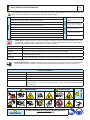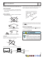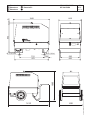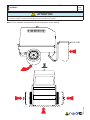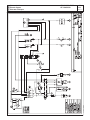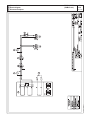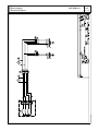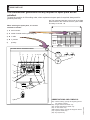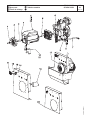
1
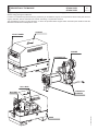
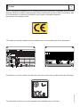
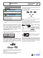
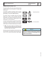
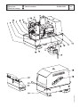
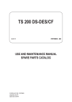
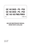
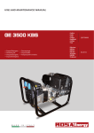
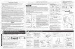
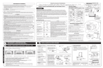
1212 GE 6000 SX/GS GE 6000 SX/GS-AVR GE 6500 SX/GS 356409003 - GB ENGLISH © MOSA 21/10/04 35640M00 preparato da UPT approvato da DITE I GB F DESCRIPTION OF THE MACHINE GE 6000 SX/GS GE 6500 SX/GS M 0 REV.4-11/11 The generating set GE 6000 / 6500 is a unit which transforms the mechanical energy, generated by endothermic engine, into electric energy, through an alternator. Is meant for industrial and professional use, powered by an endothermic engine; it is composed of various main parts such as: engine, alternator, electric and electronic controls, the fairing or a protective structure. The assembling is made on a steel structure, on which are provided elastic support which must damp the vibrations and also eliminate sounds which would produce noise. CANOPY FRONT PANEL ENGINE ALTERNATOR ROLL-BAR BASE 21/10/04 35640I VIBRATION DAMPER BATTERY M Quality system 01 REV.4-03/12 UNI EN ISO 9001 : 2008 The certifying institute, ICIM, which is a member ofthe International Certification Network IQNet, awarded the official approval to MOSA after anexamination of its operations at the head office andplant in Cusago (MI), Italy. This certification is not a point of arrival but a pledgeon the part of the entire company to maintain a levelof quality of both its products and services whichwill continue to satisfy the needs of its clients, aswell as to improve the transparency and thecommunications regarding all the company’s activesin accordance with the official procedures and inharmony with the MOSA Manual of Quality. The advantages for MOSA clients are: ·Constant quality of products and services at thehigh level which the client expects; ·Continuous efforts to improve the products andtheir performance at competitive conditions; ·Competent support in the solution of problems; ·Information and training in the correct applicationand use of the products to assure the security ofthe operator and protect the environment; ·Regular inspections by ICIM to confirm that therequirements of the company’s quality systemand ISO 9001 are being respected. All these advantages are guaranteed by the CERTIFICATE OF QUALITY SYSTEM No.0192 issued by ICIM S.p.A. - Milano (Italy ) - www.icim.it 10/10/02 M01-GB MOSA has certified its quality system according to UNI EN ISO 9001:2008 to ensure a constant, highquality of its products. This certification covers thedesign, production and servicing of engine drivenwelders and generating sets. GE 6000-6500 SX/GS Index M 1 REV.3-11/11 M 01 M 1.01 M 1.1 M 1.4 M 1.4.1 M 1.5 M 2 M 2.1 M 2.5 -…. M 2.6 M 2.7 M 2.7.1 M3 M 4.1 M 6.9 M 20 M 21 M 30 M 31 M 37 M 38.5 M 39.4 M 40.2 M 43... M 45 M 46 M 53 M 60 M 61-….. QUALITY SYSTEM COPYRIGHT NOTES CE MARK DECLARATION OF CONFORMITY TECHNICAL DATA SYMBOLS AND SAFETY PRECAUTIONS SYMBOLS INSTALLATION AND ADVICE BEFORE USE INSTALLATION AND ADVICE INSTALLATION DIMENSIONS UNPACKING TRANSPORT AND DISPLACEMENTS ASSEMBLY: CTM 2 SET-UP FOR OPERATION STARTING AND STOPPING THE ENGINE CONTROLS LEGEND CONTROLS USE AS A GENERATOR REMOTE CONTROL ENGINE PROTECTION ES - EV TROUBLE SHOOTING MAINTENANCE STORAGE CUST OFF DIMENSIONS ELECTRICAL SYSTEM LEGEND ELECTRICAL SYSTEM R 1 HP ... SPARE PARTS TABLES SPARE PARTS 21/10/04 35640GB I GB F M 1.01 Copyright REV.0-10/02 ! ATTENTION This use and maintenance manual is an important part of the machines in question. The assistance and maintenance personel must keep said manual at disposal, as well as that for the engine and alternator (if the machine is synchronous) and all other documentation about the machine. We advise you to pay attention to the pages concerning the security (see page M1.1). All rights are reserved to said Company. It is a property logo of MOSA division of B.C.S. S.p.A. All other possible logos contained in the documentation are registered by the respective owners. + The reproduction and total or partial use, in any form and/or with any means, of the documentation is allowed to nobody without a written permission by MOSA division of B.C.S. S.p.A. To this aim is reminded the protection of the author’s right and the rights connected to the creation and design for communication, as provided by the laws in force in the matter. In no case MOSA division of B.C.S. S.p.A. will be held responsible for any damaga, direct or indirect, in relation with the use of the given information. 10/10/02 M1-01-GB MOSA division of B.C.S. S.p.A. does not take any responsibility about the shown information on firms or individuals, but keeps the right to refuse services or information publication which it judges discutible, unright or illegal. Notes M 1-1 REV.0-10/02 INFORMATION Dear Customer, We wish to thank you for having bought a high quality set. Our sections for Technical Service and Spare Parts will work at best to help you if it were necessary. To this purpose we advise you, for all control and overhaul operations, to turn to the nearest authorized Service Centre, where you will obtain a prompt and specialized intervention. + In case you do not profit on these Services and some arts are replaced, please ask and be sure that are used exclusively original parts; this to guarantee that the performances and the initial safety prescribed by the norms in force are re-established. +The use of non original spare parts will cancel immediately any guarantee and Technical Service obligation. NOTES ABOUT THE MANUAL Before actioning the machine please read this manual attentively. Follow the instructions contained in it, in this way you will avoid inconveniences due to negligence, mistakes or incorrect maintenance. The manual is for qualified personnel, who knows the rules: about safety and health, installation and use of sets movable as well as fixed. INFORMATION OF GENERAL TYPE In the envelope given together with the machine and/or set you will find: the manual for Use Maintenance and Spare Parts, the manual for use of the engine and the tools (if included in the equipment), the guarantee (in the countries where it is prescribed by law). Our products have been designed for the use of generation for welding, electric and hydraulic system; ANY OTHER DIFFERENT USE NOT INCLUDED IN THE ONE INDICATED, relieves the manufacturer from the risks which could happen or, anyway, from that which was agreed when selling the machine. The manufacturer excludes any responsibility for damages to the machine, to the things or to persons in this case. Our products are made in conformity with the safety norms in force, for which it is advisable to use all these devices or information so that the use does not bring damage to persons or things. While working it is advisable to keep to the personal safety norms in force in the countries to which the product is destined (clothing, work tools, etc.). Do not modify for any motive parts of the machine (fastenings, holes, electric or mechanical devices, others..) if not duly authorized in writing: the responsibility coming from any potential intervention will fall on the executioner as in fact he becomes maker of the machine. You must remember that, in case you have difficulties for use or installation or others, our Technical Service is always at your disposal for explanations or interventions. The manual for Use Maintenance and Spare Parts is an integrant part of the product. It must be kept with care during all the life of the product. In case the machine and/or the set should be yielded to another user, this manual must also given to him. Do not damage it, do not take parts away, do not tear pages and keep it in places protected from dampness and heat. + Notice: this manual does not engage the manufacturer, who keeps the faculty, apart the essential characteristics of the model here described and illustrated, to bring betterments and modifications to parts and accessories, without putting this manual uptodate immediately. 10/10/02 M 1-1 GB_NEUTRO You must take into account that some figures contained in it want only to identify the described parts and therefore might not correspond to the machine in your possession. M 1.4 CE MARK REV.5-03/11 Any of our product is labelled with CE marking attesting its conformity to appliable directives and also the fulfillment of safety requirements of the product itself; the list of these directives is part of the declaration of conformity included in any machine standard equipment. Here below the adopted symbol: CE marking is clearly readable and unerasable and it can be either part of the data-plate. The indication is shown in a clear, readable and indeleble way on a sticker. 10/10/02 M1-4 GB Furthermore, on each model it is shown the noise level value; the symbol used is the following: Dichiarazione conformità Declaration of conformity Déclaration de conformité Konformitätserklärung Declaración de conformidad Declaração de conformidade BCS S.p.A. M 1.4.1 REV.1-01/13 Stabilimento di Cusago, 20090 (Mi) - Italia V.le Europa 59 Tel.: +39 02 903521 Fax: +39 02 90390466 Sede legale: Via Marradi 1 20123 Milano - Italia DICHIARAZIONE DI CONFORMITA' Déclaration de Conformité – Declaration of Conformity – Konformitätserklärung Conformiteitsverklaring – Declaración de Conformidad BCS S.p.A. dichiara sotto la propria responsabilità che la macchina: BCS S.p.A. déclare, sous sa propre responsabilité, que la machine: BCS S.p.A. declares, under its own responsibility, that the machine: BCS S.p.A. erklärt, daß die Aggregate: BCS S.p.A. verklaard, onder haar eigen verantwoordelijkheid, dat de machine: BCS S.p.A. declara bajo su responsabilidad que la máquina: GRUPPO ELETTROGENO DI SALDATURA / WELDING GENERATOR GRUPPO ELETTROGENO / POWER GENERATOR Marchio / Brand : MOSA Modello / Model : Matricola / Serial number: è conforme con quanto previsto dalle Direttive Comunitarie e relative modifiche: est en conformité avec ce qui est prévu par les Directives Communautaires et relatives modifications: conforms with the Community Directives and related modifications: mit den Vorschriften der Gemeinschaft und deren Ergänzungen übereinstimmt: in overeenkomst is met de inhoud van gemeenschapsrichtlijnemen gerelateerde modificaties: comple con los requisítos de la Directiva Comunitaria y sus anexos: 2006/42/CE - 2006/95/CE - 2004/108/CE Nome e indirizzo della persona autorizzata a costituire il fascicolo tecnico: Nom et adresse de la personne autorisée à composer le Dossier Technique: Person authorized to compile the technical file and address: Name und Adresse der zur Ausfüllung der technischen Akten ermächtigten Person: Persoon bevoegd om het technische document, en bedrijf gegevens in te vullen: Nombre y dirección de la persona autorizada a componer el expediente técnico: ing. Benso Marelli - Consigliere Delegato / COO; V.le Europa 59, 20090 Cusago (MI) – Italy Cusago, _______________ Ing. Benso Marelli Consigliere Delegato COO MM 083.0 04/06/10 M1.4.1 I GB F I GB F GE 6000 SX/GS GE 6500 SX/GS Technical data M 1.5 REV5-12/12 Technical data GE 6000 SX/GS GE 6000 SX/GS-AVR GE 6500 SX/GS *Three-phase power Stand-by **Three-phase power PRP *Single-phase power Stand-by **Single-phase power PRP *Single-phase power Stand-by **Single-phase power PRP Frequency Power factor (cos ϕ) ALTERNATOR - - 5.7 kVA (5.1 kW) / 230 V / 24.8 A 5 kVA (4.5 kW) / 230 V / 21.7 A 5.7 kVA (6 kW) / 115 V / 49.6 A 5 kVA (5 kW) / 115 V / 43.5 A 50 Hz 0.9 self-excited, self-regulated, brushless 6.5 kVA (5.2 kW) / 400 V / 9.4 A 5.7 kVA (4.6 kW) / 400 V / 8.2 A 4 kVA / 230 V / 17.4 A 50 Hz 0.8 self-excited, self-regulated, with brush Type Insulating class ENGINE Single-phase, synchronous H Three-phase, synchronous H A.C. GENERATOR Mark / Model Type / Cooling system Cylinders / Displacement Net power Stand-by Net power PRP Speed Fuel consumption Engine oil capacity Starter GENERAL SPECIFICATIONS YANMAR / L 100 N Diesel 4-Stroke / Air 1 / 435 cm3 6.5 kW (8.8 HP) 5.7 kW (7.7 HP) 3000 rpm 1.2l/h 1.6 l Electric Fuel tank capacity 23 l Running time (75% of PRP) 19 h Protection IP 23 *Dimensions max. Lxwxh 1020x645x930 *Weight (dry) 206 Kg Measured acoustic power LwA (LpA pression) 92 dB(A) (67 dB(A) @ 7 m) Guaranteed acoustic power LwA (LpA pression) 93 dB(A) (68 dB(A) @ 7 m) 2000 / 14 / CE * Dimensions and weight are inclusive of all parts. 206 Kg 91 dB(A) (66 dB(A) @ 7 m) 92 dB(A) (67 dB(A) @ 7 m) 2000 / 14 / CE OUTPUT Declared power according to ISO 8528-1 (temperature 25°C, 30% relative humidity, altitude 100 m above sea level). (*Stand-by) = maximum available power for use at variable loads for a yearly number of hours limited at 500 h. No overload is admitted. (**Prime power PRP) = maximum available power for use at variable loads for a yearly illimited number of hours. The average power to be taken during a period of 24 h must not be over 80% of the PRP. It’s admitted overload of 10% each hour every 12 h. In an approximative way one reduces: of 1% every 100 m altitude and of 2.5% for every 5°C above 25°C. Lp a 1 meter = 95 dB(A) - 8 dB(A) = 87 dB(A) Lp a 4 meters = 95 dB(A) - 20 dB(A) = 75 dB(A) PLEASE NOTE: the symbol according to 2000/14/CE directive. 2000 / 14 / CE Lp a 7 meters = 95 dB(A) - 25 dB(A) = 70 dB(A) Lp a 10 meters = 95 dB(A) - 28 dB(A) = 67 dB(A) when with acoustic noise values, indicates that the device respects noise emission limits 21/10/04 35640GB ACOUSTIC POWER LEVEL ATTENTION: The concrete risk due to the machine depends on the conditions in which it is used. Therefore, it is up to the enduser and under his direct responsibility to make a correct evaluation of the same risk and to adopt specific precautions (for instance, adopting a I.P.D. -Individual Protection Device) Acoustic Noise Level (LWA) - Measure Unit dB(A): it stands for acoustic noise released in a certain delay of time. This is not submitted to the distance of measurement. Acoustic Pressure (Lp) - Measure Unit dB(A): it measures the pressure originated by sound waves emission. Its value changes in proportion to the distance of measurement. The here below table shows examples of acoustic pressure (Lp) at different distances from a machine with Acoustic Noise Level (LWA) of 95 dB(A) M 2 SYMBOLS AND SAFETY PRECAUTIONS REV.0-11/99 - The symbols used in this manual are designed to call your attention to important aspects of the operation of the machine as well as potential hazards and dangers for persons and things. IMPORTANT ADVICE - Advice to the User about the safety: +N.B.: The information contained in the manual can be changed without notice. Potential damages caused in relation to the use of these instructions will not be considered because these are only indicative. Remember that the non observance of the indications reported by us might cause damage to persons or things. It is understood, that local dispositions and/or laws must be respected. WARNING ! Situations of danger - no harm to persons or things Do not use without protective devices provided Removing or disabling protective devices on the machine is prohibited. Do not use the machine if it is not in good technical condition The machine must be in good working order before being used. Defects, especially those which regard the safety of the machine, must be repaired before using the machine. SAFETY PRECAUTIONS ! DANGEROUS This heading warns of an immediate danger for persons as well for things. Not following the advice can result in serious injury or death. ! WARNING This heading warns of situations which could result in injury for persons or damage to things. ! CAUTION To this advice can appear a danger for persons as well as for things, for which can appear situations bringing material damage to things. ! IMPORTANT ! NOTE ! ATTENTION These headings refer to information which will assis you in the correct use of the machine and/or accessories. 26/11/99 M2GB SYMBOLS IN THIS MANUAL M 2-1 SYMBOLS AND SAFETY PRECAUTIONS REV.2-06/10 STOP - Read absolutely and be duly attentive Read and pay due attention ! GENERAL ADVICE - If the advice is not respected damage can happen to persons or things. HIGH VOLTAGE - Attention High Voltage. There can be parts in voltage, dangerous to touch. The non observance of the advice implies life danger. FIRE - Danger of flame or fire. If the advice is not respected fires can happen. HEAT - Hot surfaces. If the advice is not respected burns or damage to things can be caused. EXPLOSION - Explosive material or danger of explosion. in general. If the advice is not respected there can be explosions. WATER - Danger of shortcircuit. If the advice is not respected fires or damage to persons can be caused. SMOKING - The cigarette can cause fire or explosion. If the advice is not respected fires or explosions can be caused. ACIDS - Danger of corrosion. If the advice is not respected the acids can cause corrosions with damage to persons or things. PROHIBITIONS No harm for persons Use only with safety clothing It is compulsory to use the personal protection means given in equipment. Use only with safety clothing It is compulsory to use the personal protection means given in equipment. Use only with safety protections It is a must to use protection means suitable for the different welding works. Use with only safety material It is prohibited to use water to quench fires on the electric machines. Use only with non inserted voltage It is prohibited to make interventions before having disinserted the voltage. No smoking It is prohibited to smoke while filling the tank with fuel. No welding It is forbidden to weld in rooms containing explosive gases. ADVICE No harm for persons and things Use only with safety tools, adapted to the specific use It is advisable to use tools adapted to the various maintenance works. Use only with safety protections, specifically suitable It is advisable to use protections suitable for the different welding works. Use only with safety protections It is advisable to use protections suitable for the different daily checking works. WRENCH - Use of the tools. If the advice is not respected damage can be caused to things and even to persons. Use only with safety protections It is advisable to use all protections while shifting the machine. PRESSION - Danger of burns caused by the expulsion of hot liquids under pressure. Use only with safety protections It is advisable to use protections suitable for the different daily checking works.and/or of maintenance. ACCES FORBIDDEN to non authorizad peaple. 26/11/99 M2-1GB SYMBOLS M 2-5 INSTALLATION AND ADVICE BEFORE USE REV.0-06/00 ! The installation and the general advice concerning the operations, are finalized to the correct use of the machine, in the place where it is used as generator group and/or welder. Stop engine when fueling CHECKING BOARD Do not smoke, avoid flames, sparks or electric tools when fueling. ENGINE Unscrew the cap slowly to let out the fuel vapours. Slowly unscrew the cooling liquid tap if the liquid must be topped up. The vapor and the heated cooling liquid under pressure can burn face, eyes, skin. Do not fill tank completely. Wipe up spilled fuel before starting engine. Shut off fuel of tank when moving machine (where it is assembled). Do not touch electric devices if you are barefoot or with wet clothes. Always keep off leaning surfaces during work operations. Static electricity can demage the parts on the circuit. An electric shock can kill Avoid spilling fuel on hot engine. Sparks may cause the explosion of battery vapours + FIRST AID. In case the operator shold be sprayed by accident, from corrosive liquids a/o hot toxic gas or whatever event which may cause serious injuries or death, predispose the first aid in accordance with the ruling labour accident standards or of local instructions. Skin contact Wash with water and soap Eyes contact Irrigate with plenty of water, if the irritation persists contact a specialist Ingestion Do not induce vomit as to avoid the intake of vomit into the lungs, send for a doctor Suction of liquids from If you suppose that vomit has entered the lungs (as in case of spontaneous vomit) take the subject to the lungs hospital with the utmost urgency In case of exposure to high concentration of vapours take immediately to a non polluted zone the person involved Inhalation + FIRE PREVENTION. In case the working zone,for whatsoever cause goes on fire with flames liable to cause severe wounds or death, follow the first aid as described by the ruling norms or local ones. EXTINCTION MEANS Carbonate anhydride (or carbon dioxyde) powder, foam, nebulized water Not to be used Avoid the use of water jets Other indications Cover eventual shedding not on fire with foam or sand, use water jets to cool off the surfaces close to the fire Particular protection Wear an autorespiratory mask when heavy smoke is present Useful warnings Avoid, by appropriate means to have oil sprays over metallic hot surfaces or over electric contacts (switches,plugs,etc.). In case of oil sprinkling from pressure circuits, keep in mind that the inflamability point is very low. ! CAUTION ! WARNING THE MACHINE MUST NOT BE USED IN AREAS WITH EXPLOSIVE ATMOSPHERE 10/06/00 M2-5I WARNING ! ! DANGEROUS Appropriated M 2.6 INSTALLATION AND ADVICE REV.1-06/07 INSTALLATION AND ADVICE BEFORE USE GASOLINE ENGINES + Use in open space, air swept or vent exhaust gases, which contain the deathly carbone oxyde, far from the work area. Check that the air gets changed completely and the hot air sent out does not come back inside the set so as to cause a dangerous increase of the temperature. 1,5 m DIESEL ENGINES + Use in open space, air swept or vent exhaust gases far from the work area. 1,5 1,5 m m UT P UICTO AOR TC DISS SU GHAA EX + Make sure that the machine does not move during the work: block it possibly with tools and/or devices made to this purpose. MOVES OF THE MACHINE + At any move check that the engine is off, that there are no connections with cables which impede the moves. PLACE OF THE MACHINE ! POSITION Place the machine on a level surface at a distance of at least 1,5 m from buildings or other plants. ATTENTION For a safer use from the operator DO NOT fit the machine in locations with high risk of flood. Please do not use the machine in weather conditions which are beyond IP protection shown both in the data plate and on page named "technical data" in this same manual. Maximum leaning of the machine (in case of dislevel) 10° = 20° max 10° 10° = 20° max 26/11/99 M2-6GB 10° Installazione Installation Installation Luftzirkulation Instalación GE 6000-6500 SX/GS GE 7000 SX/GA-EAS M 2.7 REV.1-09/06 21/10/04 35640I I GB F I Dimensioni Dimensions Dimensions Abmessungen Dimensiones GE 6000/6500 SX/GS GE 7000 SX/GA M 2.7.1 REV.0-10/01 1040 648 864 50~ GB F Ø 14 n°2 fori Ø 14 n°2 fori 530 600 128 1095 701 970 820 21/10/04 35640I 1410 M 3 UNPACKING REV.1-02/04 NOTE ! + Be sure that the lifting devices are: correctly mounted, adequate for the weight of the machine with it’s packaging, and conforms to local rules and regulations. When receiving the goods make sure that the product has not suffered damage during the transport, that there has not been rough handling or taking away of parts contained inside the packing or in the set. In case you find damages, rough handling or absence of parts (envelopes, manuals, etc.), we advise you to inform immediately our Technical Service. For eliminating the packing materials, the User must keep to the norms in force in his country. 1 A B 1)Take the machine (C) out of the shipment packing. Take out of the envelope (A) the user’s manual (B). 2)Read: the user’s manual (B), the plates fixed on the machine, the data plate. C 30/03/00 M3GB 2 TRANSPORT AND DISPLACEMENTS COVERED UNITS M 4-1 REV.2-09/11 ! NOTE Transportation must always take place with the engine off, electrical cables and starting battery disconnected and fuel tank empty. Be sure that the lifting devices are: correctly mounted, adequate for the weight of the machine with it’s packaging, and conform to local rules and regulations. Only authorized persons involved in the transport of the machine should be in the area of movement. DO NOT LOAD OTHER PARTS WHICH CAN MODIFY WEIGHT AND BARICENTER POSITION. IT IS STRICTLY FORBIDDEN TO DRAG THE MACHINE MANUALLY OR TOW IT BY ANY VEHICLE (model with no CTM accessory). If you did not keep to the instructions, you could damage the structure of the machine. 15/01/01 M4GB Weight max. per person: 35 kg Total max. weight; 140 kg CTM2 ASSEMBLY M 6.9 REV.0-06/00 ! ATTENTION The CTM accessory cannot be removed from the machine and used separately (actioned manually or following vehicles) for the transport of loads or anyway for used different from the machine movements. 29/10/01 M6GB Note: Lift the machine and assemble the parts as shown in the drawing Set-up for operation (Engine diesel) Air cooled systems M 20 REV.1-09/05 OIL BATH AIR FILTER BATTERY WITHOUT MAINTENANCE Connect the cable + (positive) to the pole + (positive) of the battery (after having taken away the protection), by properly tightening the clamp. Fill the air filter using the same engine oil up to the level indicated on the filter. FUEL Check the state of the battery from the colour of the warning light which is in the upper part. ! - Green colour: battery OK - Black colour: battery to be recharged - White colour: battery to be replaced DO NOT OPEN THE BATTERY. LUBRICANT RECOMMENDED OIL MOSA recommends selecting AGIP engine oil. Refer to the label on the motor for the recommended products. ATTENTION Do not smoke or use open flames during refuelling operations, in order to avoid explosions or fire hazards. Fuel fumes are highly toxic; carry out operations outdoors only, or in a wellventilated environment. Avoid accidentally spilling fuel. Clean any eventual leaks before starting up motor. Refill the tank with good quality diesel fuel, such as automobile type diesel fuel, for example. For further details on the type of diesel fuel to use, see the motor operating manual supplied. Do not fill the tank completely; leave a space of approx. 10 mm between the fuel level and the wall of the tank to allow for expansion. REFUELLING AND CONTROL: Carry out refuelling and controls with motor at level position. 1. Remove the oil-fill tap (24) 2. Pour oil and replace the tap 3. Check the oil level using the dipstick (23); the oil level must be comprised between the minimum and maximum indicators. ! ATTENTION It is dangerous to fill the motor with too much oil, as its combustion can provoke a sudden increase in rotation speed. DRY AIR FILTER Check that the dry air filter is correctly installed and that there are no leaks around the filter which could lead to infiltrations of non-filtered air to the inside of the motor. In rigid environmental temperature conditions, use special winterized diesel fuels or specific additives in order to avoid the formation of paraffin. GROUNDING CONNECTION The grounding connection to an earthed installation is obligatory for all models equipped with a differential switch (circuit breaker). In these groups the generator star point is generally connected to the machine’s earthing; by employing the TN or TT distribution system, the differential switch guarantees protection against indirect contacts. In the case of powering complex installations requiring or employing additional electrical protection devices, the coordination between the protection devices must be verified. For the grounding connection, use the terminal (12); comply to local and/or current regulations in force for electrical installations and safety. 16/07/03 M20-R-A-GB Please refer to the motor operating manual for the recommended viscosity. I GB F GE 6000/6500 SX/GS GE 6000/6500 DES/GS-L GE 7000 SX/GA ENGINE STARTING - STOPPING THE ENGINE Check daily M 21 REV.1-09/06 STOPPING THE ENGINE Before stopping the engine it is compulsory to effect the following operations: - stop to draw three/single-phase current from the auxiliary sockets. NOTE ! Do not alter the primary conditions of regulation and do not touch the sealed parts. STARTING THE ENGINE OFF ON START Introduce the key (Q1), turn it clockwise completely, leaving it as soon as the engine starts. Make sure that the unit is not supplying any power. Disconnect the electrical protection device (D) lever downward. OFF ON START Let the engine run for some minutes before drawing the load. Stop the engine turning the key (Q1) it counter clockwise, OFF position, then take it out. NB.: for safety reason the key must be kept by qualified personel. ! CAUTION ! CAUTION If the engine fails to start, do not insist for at least 15 seconds. Space the further operations waiting for at least 4 minutes. RUNNING-IN During the first 50 hours of operation, do not use more than 60% of the maximum output power of the unit and check the oil level frequently, in any case please stick to the rules given in the engine use manual. 21/10/04 35640GB lnsert the electric protection device (D) lever towards above, see page M37 – M 30 CONTROLS LEGENDE REV.2-07/08 Hydraulic oil level light Welding socket ( + ) Welding socket ( - ) Earth terminal A.C. socket Accelerator lever Feed pump 48V D.C. socket Engine air filter Oil level dipstick Engine oil reservoir cap Hydraulic oil reservoir cap Water filling cap Fuel prefilter Fuel tank cap Muffler Stop control Engine protection cover Engine cooling/alternator fan belt Oil drain tap Hydraulic oil drain tap Water drain tap Exhaust tap for tank fuel Button Start button Booster socket 12V Booster socket 24V Battery charge fuse Space for remote control Remote control Space for E.A.S. Space for PAC Fuel pump Electric start socket Reset button PTO HI Quick coupling m. PTO HI Quick coupling f. PTO HI Hydraulic oil filter Battery charger thermal switch Engine thermal switch Aux current thermal switch Supply thermal switch wire feeder-42V Pre-heater (spark plug) thermal switch Supply thermal switch oil/water heather Electropump thermal switch No load voltage control Choke control Auxiliary / welding current control Cellulosic electrodes control Voltmeter relay Warning lights Selecting knob Load commut. push button Starting push button Operating mode selector Power on warning light Display Wire connection unit Selector Setting confirmation Fuel valve Oil syringe Insulation monitoring Button indicating light 30 l/1' PTO HI Engine control unit EP2 E.A.S. connector B4 B5 C2 C3 C6 D D1 D2 E2 E6 E7 F F3 F5 F6 G1 H2 H6 H8 I2 I3 I4 I5 I6 I8 L L5 L6 M M1 M2 M5 M6 N N1 N2 N5 N6 O1 P P8 Q1 Q3 Q4 Q7 R3 S S1 S3 S6 S7 T T4 T5 T7 U U3 U4 U5 U7 V V4 V5 W1 W3 Exclusion indicating light PTO HI Auxiliary current push button Fuel level light E.A.S. PCB Control unit for generating sets QEA Ground fault interrupter ( 30 mA ) Engine control unit and economiser EP1 Ammeter Frequency meter Frequency rpm regulator Voltmeter regulator Fuse Stop switch Warning light, high temperature Arc-Force selector Fuel level transmitter Voltage commutator Fuel electro pump Engine control unit EP7 48V A.C. socket Welding scale switch Preheating indicator Y/ switch Start Local/Remote selector AUTOIDLE switch A.C. output indicator Emergency button Choke button Hour counter Warning level light Contactor Engine control unit EP5 CC/CV switch Voltmeter Battery charge warning light Thermal-magnetic circuit breaker/ Ground fault interrupter Pre-heat push-button Connector - wire feader Oil pressure warning light/Oil alert Welding arc regulator Water in fuel Starter key Derivation box Battery charge sockets Welding selector mode Siren Welding ammeter Battery Engine control unit EP4 Wire feeder supply switch Plug 230V singlephase Welding current regulator Dirty air filter warning light/indicator Earth leakage relay Analogic instrument V/Hz Current trasformer R.P.M. adjuster Polarity inverter remote control Relase coil Engine control unit EP6 Welding voltage voltmeter Polarity inverter control Oil pressure indicator Remote control switch Selection push button 30 l/1' PTO HI W5 X1 Y3 Y5 Z2 Z3 Z5 Battery voltmeter Remote control socket Button indicating light 20 l/1' PTO HI Commutator/switch, serial/parallel Thermal-magnetic circuit breaker Selection push button 20 l/1' PTO HI Water temperature indicator 10/05/01 M30-GB 4A 9 10 12 15 16 17 19 22 23 24 24A 24B 25 26 27 28 29 30 31 31A 31B 31C 32 33 34 34A 35 36 37 42 42A 47 49 54 55 55A 56 59 59A 59B 59C 59D 59E 59F 63 66 67A 68 69A 70 71 72 73 74 75 76 79 86 86A 87 88 A3 A4 B2 B3 Comandi Controls Commandes Bedienelemente Mandos GE 6000 (230V Vers.) GE 6000 SX/GS GE 6500 SX/GS M 31 REV.1-09/06 GE 6000 (230V 110V Vers.) GE 6500 (400V 230V Schuko Vers.) GE 6500 (400V 230V Vers.) 21/10/04 35640I I GB F USE AS A GENERATOR REV.0-06/99 ☞ It is strictly forbidden to connect the group to the public mains a/o to another source of electric power. WARNING Sockets are not self-locked: tension is avaible immediately after starting also with no plug. CT 230 SX GE 6000 - 6500 SX/GS GE 7000 SX/GA M 37 THERMOPROTECTION If you overload the genset the thermoprotection will automatically switch off. lf the thermoprotection is released, disconnect all the connected loads. CLOSED OPEN WARNING ☞ At the beginning of every work, check the electric parameters and/or the controls placed on the front. Make sure that the ground connection (12) is efficent (keep to installation local rules and/or to national laws), in order to integrate or ensure the working of varius electric protection devices referring to the several distribution system TT/TN/IT, operation unnecessary for machine with isometer. - See page M 20-21. Check the voltmeter (N) shows the voltage three or single-phase has to be drawn. Nominal voltage 230V 400V Indicative no-load voltage +10% +10% Connect up the machine, using proper plugs and cables in good condition to the AC socket (15) to draw single or three-phase power, or, by cables with adeguate section, to the terminal board, placed inside the derivation box (Q3). Using several sockets at tha same time, the maximum power possible is that indicated on the data plate. The max. continuous power of the generating set or the load current must not be exceeded. Reset the thermoprotection pressing the central pole. When reset, connect the loads again. In case the protection should act furtherly, check: the connections, the wires or others, and if necessary call the Assistance Service. AvoId to hold the central pole of the PRESS TO thermoprotection pressed for a long time. RESET Otherwise, in case of trouble, it will not click, damaging the generating set. GROUND FAULT INTERRUPTER (GFI) Turn on the GFI safety-switch (D) by pushing it upwards. The GFI is a safety device which protects the circuit in the event of a malfunction. In this case the switch disconnects the three and single-phase circuit when in any part of the electric connections a current leakage of more than 30 mA occurs. 06/04/05 37285-GB The areas, access of which is forbidden to unqualified personel, are: - the control switchboard (front), the exhaust of the endothermic engine. ACCESSORY USE REMOTE CONTROL TCM 15 - 6 ! M 38.5 REV.1-07/11 MAKE SURE When the TCM 15 - 6 is used, it is not possible to connect the E.A.S automatic intervention unit. USE OF THE REMOTE CONTROL TCM 15 The coupling of the TCM 15 with the generating set, permits to work far from the set itself. The remote control is connected to the front plate, with a multiple connector. The TCM 15 assures the following fonctions: - starting (starting key Q1) - stop (starting key Q1) - choke control (L6) TCM 15 OFF OFF ON CHOKE L6 START Q1 USE OF THE REMOTE CONTROL TCM 6 The coupling of the TCM 6 with the generating set, ready for remot starting, permits to work far from the set itself. The remote control is connected to the front plate, and/or rear plate, with a multiple connector. PUSH AND SCREW TIGHT TCM 6 The TCM 6 assures the following fonctions: - starting (starting key Q1) - stop (starting key Q1) - indication of oil low pressure (warning light O1) OFF OFF ON START To stop the set turn the key to the position "OFF". O1 Q1 PUSH AND SCREW TIGHT 29/11/99 M38GB N.B.: the position of the selector LOCAL START/ REMOTE START (l6) on the generating sets must be on the position "REMOTE START". USE OF THE PROTECTION ENGINE PROTECTION ES - EV M 39.4 REV..1-04/03 ENGINE PROTECTION (ES - EV) The devices ES or EV ensure the protection of the engine in case of low oil pressure or engine high temperature. The system consist of electronic card of control and check, and of an engine stop device: solenoid (ElettroStop), electrovalve (ElettroValvola) High temperature The device enter in operation when the engine starts and, in case of low oil pressure and high temperature, will stop the machine and show the cause of the stop with the warning light of high temperature or low oil pressure. In case of low oil pressure, check the level and if it is correct, call the Service Station. In case of high temperature, make sure that there are no leaves and/or pieces of material obstructing the air ducts. Once the cause of the problem is removed, to reset the protection, it is enough to report the ignition key (Q1) on "OFF" position and start the engine again. ! NOTE THE ENGINE PROTECTIONS DO NOT WORK WHEN THE OIL IS OF LOW QUALITY BECAUSE NOT CHANGED REGULARLY AT INTERVALS AS PRESCRIBED IN THE OWNER’S ENGINE MANUAL. 07/05/01 M39GB + N.B.: if the unit is used as a generator in hot climates and with loads near to the maximum, the protection device can be triggered off, please reduce the load of the engine. Low oil pressure Diesel engine Troubleshooting M 40.2 REV.3-07/06 Problem The motor does not start up Possible cause Solution ENGINE 1) Start-up switch (I6) (where it is assembled) in 1) Check position incorrect position 2) Emergency button (L5) pressed 2) Unblock 3) Preheating (where it is assembled) 3) Lacking or insufficient preheating phase for sparkplugs. Malfunction in circuit: repair. 4) Engine control unit or starting key faulty. 4) Replace 5) Battery low 5) Recharge or replace. Check the battery charge circuit on motor and automatic panel. 6) Battery cable terminals loose or corroded 6) Tighten and clean. Replace if corroded. 7) Start-up motor defective 7) Repair or replace. 8) No fuel or air in feed circuit 8) Refill tank, un-aerate the circuit. 9) Malfunction on feed circuit: defective pump, 9) Ask for intervention of Service Department. injector blocked, etc. 10) Air filter or fuel filter clogged 10) Clean or replace 11) Air in the gasoil filter. 11) Take the air out filling the filter with gasoil. 12) Motor stopping device defective 12) Replace. 13) Malfunction on electrical power circuit on ge- 13) Check and repair. nerator control panel 1) Clean or replace. The motor does not accelerate. 1) Air filter or fuel filter clogged. 2) Malfunction on feed circuit: defective pump, 2) Ask for intervention of Service Department. Inconstant speed. injector blocked, etc. 3) Eliminate excess oil. 3) Oil level too high. 4) Motor speed regulator defective. 4) Ask for intervention of Service Department Black smoke 1) Air filter clogged. 1) Clean or replace 2) Overload. 2) Check the load connected and diminish. 3) Injectors defective. Injection pump requires 3) Ask for intervention of Service Department. calibration. White smoke 1) Oil level too high. 1) Eliminate excess oil. 2) Motor cold or in prolonged operation with little 2) Insert load only with motor sufficiently hot or no load. 3) Ask for intervention of Service Department. 3) Segments and/or cylinders worn out. Too little power provided by 1) Air filter clogged. 1) Clean or replace. motor. 2) Insufficient fuel distribution, impurities or water 2) Check the feed circuit, clean and refill once in feed circuit. again. 3) Injectors dirty or defective. 3) Ask for intervention of Service Department. 1) 2) 3) 4) High temperature 1) Overload 2) Insufficient ventilation. 3) 4) 5) 6) 7) Oil level insufficient Air filter clogged. Oil pump defective. Alarm malfunction. 1) 2) 3) 4) Reset level. Check for leaks. Replace filter. Ask for intervention of Service Department. Check the sensor and electrical circuit. 1) Check the load connected and diminish. 2) Check the cooling vent and relative transmission belts Insufficient coolant liquid (Only for water cooled 3) Restore level. Check for leaks or breakage in motors) the entire cooling circuit, pipes, couplings, etc. Water radiator or oil clogged (where it is as- 4) Clean cooling fins on radiator sembled) Water circulating pump defective (Only for 5) Ask for intervention of Service Department water cooled motors) Injectors defective. Injection pump requires 6) Ask for intervention of Service Department calibration Alarm malfunction 7) Check the sensor and electrical circuit 28/01/03 M40I_1500G_GE Low oil pressure Troubleshooting Diesel engine M 40.2.1 REV.4-03/11 Problem Possible cause Solution GENERATOR Absence of output voltage 1) Check position 2) Check connections and working of the switch, repair or replace 3) Check the load connected and diminish Protection tripped due to overload Differential protection device tripped. (Differential 4) Check on the entire installation: cables, connections, utilities connected have no defective sheathing which switch, differential relay) may cause incorrect currents to ground 5) Replace Protection devices defective 6) Carry out external spark test as indicated in Alternator not sparked alternator manual. Ask for intervention of Service Department 7) Check winding, diodes, etc. on alternator (Refer to Alternator defective alternator manual) Repair or replace. Ask for intervention of Service Department 1) Voltage switch in position 0 2) Voltage switch faulty 3) 4) 5) 6) 7) 1) Regulate speed to its nominal no-load value No-load voltage too low or too high 1) Incorrect motor running speed 2) Voltage regulating device (where it is assembled) 2) Adjust regulator device as indicated in alternator manual, or replace. For generators with double defective or requires calibration voltage control AVR and COMPOUND, act on the 3) Alternator defective excitation circuit as shown in the alternator manual. 3) Check winding, diodes, etc. on alternator (Refer to alternator manual) Repair or replace Ask for intervention of Service Department Unstable tension 1) Contacts malfunctioning 2) Irregular rotation of motor 3) Alternator defective 1) Check the load connected and diminish 2) Reduce or rephase load 3) Check winding, diodes, etc. on alternator (Refer to alternator manual) Repair or replace Ask for intervention of Service Department 1) Check electrical connections and tighten 2) Ask for intervention of Service Department 3) Check winding, diodes, etc. on alternator (Refer to alternator manual) Repair or replace Ask for intervention of Service Department 12/06/03 M40GB_1500G_GE Corrected no-load voltage too low 1) Incorrect motor running speed due to overload with load 2) Load with cos j less than 0.8 3) Alternator defective M 43 MAINTENANCE REV.0-06/10 MOVING PARTS can injure WARNING ●● Have qualified personnel do maintenance and troubleshooting work. ●● Stop the engine before doing any work inside the machine. If for any reason the machine must be operated while working inside, pay attention moving parts, hot parts (exhaust manifold and muffler, etc.) electrical parts which may be unprotected when the machine is open. ●● Remove guards only when necessary to perform maintenance, and replace them when the maintenance requiring their removal is complete. ●● Use suitable tools and clothes. ●● Do not modify the components if not authorized. - See pag. M1.1 - NOTE By maintenance at care of the utilizer we intend all the operatios concerning the verification of mechanical parts, electrical parts and of the fluids subject to use or consumption during the normal operation of the machine. For what concerns the fluids we must consider as maintenance even the periodical change and or the refills eventually necessary. Maintenance operations also include machine cleaning operations when carried out on a periodic basis outside of the normal work cycle. The repairs cannot be considered among the maintenance activities, i.e. the replacement of parts subject to occasional damages and the replacement of electric and mechanic components consumed in normal use, by the Assistance Authorized Center as well as by manufacturer. The replacement of tires (for machines equipped with trolleys) must be considered as repair since it is not delivered as standard equipment any lifting system. The periodic maintenance should be performed according to the schedule shown in the engine manual. An optional hour counter (M) is available to simplify the determination of the working hours. ! IMPORTANT In the maintenance operations avoid that polluting substances, liquids, exhausted oils, etc. bring damage to people or things or can cause negative effects to surroindings, health or safety respecting completely the laws and/or dispositions in force in the place. ENGINE and ALTERNATOR PLEASE REFER TO THE SPECIFIC MANUALS PROVIDED. Every engine and alternator manufacturer has HOT surface can hurt you maintenance intervals and specific checks for each model: it is necessary to consult the specific engine or alternator USER AND MAINTENANCE manual. VENTILATION Make certain there are no obstructions (rags, leaves or other) in the air inlet and outlet openings on the machine, alternator and motor. ELECTRICAL PANELS Check condition of cables and connections daily. Clean periodically using a vacuum cleaner, DO NOT USE COMPRESSED AIR. DECALS AND LABELS All warning and decals should be checked once a year and replaced if missing or unreadable. STRENUOUS OPERATING CONDITIONS Under extreme operating conditions (frequent stops and starts, dusty environment, cold weather,extended periods of no load operation, fuel with over 0.5% sulphur content) do maintenance more frequently. BATTERY WITHOUT MAINTENANCE DO NOT OPEN THE BATTERY The battery is charged automatically from the battery charger circuit suppplied with the engine. Check the state of the battery from the colour of the warning light which is in the upper part. - Green colour: battery OK - Black colour: battery to be recharged - White colour: battery to be replaced ! NOTE THE ENGINE PROTECTION NOT WORK WHEN THE OIL IS OF LOW QUALITY BECAUSE NOT CHARGED REGULARLY AT INTERVALS AS PRESCRIBED IN THE OWNER’S ENGINE MANUAL. 05/09/05 M43GB ! M 43.1 MAINTENANCE REV.0-09/05 ! ATTENTION Maintenance operations on the electricity-generating group prearranged for automatic operation must be carried l out with the panel in RESET mode. Maintenance operations on the installation’s electrical panels must be carried out in complete safety by cutting l off all external power sources: ELECTRICAL POWER, GROUP and BATTERY. For the electricity-generating groups prearranged for automatic operation, in addition to carrying out all periodic maintenance operations foreseen for normal usage, various operations must be carried out that are necessary in relation to the specific type of use. The electricity-generating group in fact must be continuously prepared for operation, even after prolonged periods of inactivity. MAINTENANCE GENERATING SET WITH AUTOMATIC BOARD EVERY WEEK 1. TEST or AUTOMATIC TEST cycle to keep the generating set constantly operative 2. Check all levels: engine oil, fuel level, battery electrolyte,, if necessary top it up. 3. Control of electrical connections and cleaning of control panel EVERY MONTH AND/OR AFTER INTERVENTION ON LOAD NO-LOAD WITH LOAD X X X X X EVERY YEAR X 05/09/05 M43GB l Carry out motor oil change at least once a year, even if the requested number of hours has not been attained. M 45 STORAGE REV.0-06/07 In case the machine should not be used for more than 30 days, make sure that the room in which it is stored presents a suitable shelter from heat sources, weather changes or anything which can cause rust, corrosion or damages to the machine. + Have qualified personnel prepare the machine for storage. GASOLINE ENGINE Start the engine: lt will run until it stops due to the lack of fuel. Drain the oil from the engine sump and fill it with new oil (see page M25). Pour about 10 cc of oil into the spark plug hole and screw the spark plug, after having rotated the crankshaft several times. Rotate the crankshaft slowly until you feel a certain compression, then leave it. In case of necessity for first aid and of fire prevention, see page. M2.5. ! IMPORTANT In the storage operations avoid that polluting substances, liquids, exhausted oils, etc. bring damage to people or things or can cause negative effects to surroindings, health or safety respecting completely the laws and/or dispositions in force in the place. In case the battery, for the electric start, is assembled, disconnect it. Clean the covers and all the other parts of the machine carefully. Protect the machine with a plastic hood and store it in o dry place. DIESEL ENGINE For short periods of time it is advisable, about every 10 days, to make the machine work with load for 15-30 minutes, for a correct distribution of the lubricant, to recharge the battery and to prevent any possible bloking of the injection system. For long periods of inactivity, turn to the after soles service of the engine manufacturer. Clean the covers and all the other parts of the machine carefully. 04/06/07 M45GB Protect the machine with a plastic hood and store it in a dry place. M 46 CUST OFF REV.0-06/07 + Have qualified personnel disassemble the machine and dispose of the parts, including the oil, fuel, etc., in a correct manner when it is to be taken out of service. As cust off we intend all operations to be made, at utilizer’s care, at the end of the use of the machine. This comprises the dismantling of the machine, the subdivision of the several components for a further reutilization or for getting rid of them, the eventual packing and transportation of the eliminated parts up to their delivery to the store, or to the bureau encharged to the cust off or to the storage office, etc. In case of necessity for first aid and fire prevention, see page M2.5. ! IMPORTANT In the cust-off operations avoid that polluting substances, liquids, exhausted oils, etc. bring damage to people or things or can cause negative effects to surroindings, health or safety respecting completely the laws and/or dispositions in force in the place. The several operations concerning the cust off, involve the manipulation of fluids potentially dangerous such as: lubricating oil and battery electrolyte. The dismantling of metallic parts liable to cause injuries or wounds, must be made wearing heavy gloves and using suitable tools. The getting rid of the various components of the machine must be made accordingly to rules in force of law a/o local rules. Particular attention must be paid when getting rid of: lubricating oils, battery electrolyte, and inflamable liquids such as fuel, cooling liquid. The machine user is responsible for the observance of the norms concerning the environment conditions with regard to the elimination of the machine being cust off and of all its components. In case the machine should be cust off without any previous disassembly it is however compulsory to remove: - tank fuel - engine lubricating oil - cooling liquid from the engine - battery 04/06/07 M45GB NOTE: BCS is involved with custing off the machine only for the second hand ones, when not reparable. This, of course, after authorization. GE 6000/6500 SX/GS GE 7000 SX/GA I GB F REV.0-10/04 Legenda schema elettrico Electrical system legende A B D F G H I M N G1 L1 M1 N1 O1 R1 S1 U1 V1 Z1 Z2 B3 N3 P4 Y5 H6 I6 A: B: D: F: G: H: I: M: N: G1: L1: M1: N1: O1: R1: S1: U1: V1: Z1: Z2: B3: N3: P4: Y5: H6: I6: Generator Klemmleiste FI-Schalter (GFI) Sicherung Steckdose 400V 3-phasig Steckdose 230V 1-phasig Steckdose 110V 1-phasig Stundenzähler Voltmeter Füllstandssensor Kraftstoff Öldruckschalter Warnleuchte Kraftstoff Warnleuchte Batterieladung Warnleuchte Öldruck Anlasser Batterie Laderegler Batterie Steuereinheit Magnetventil Magnetventil Thermomagnetschalter (Si-Automat) Steckdose EAS/Fernstart Relais Thermosicherung Anzeige Wassertemperatur Kraftstoffpumpe 12V Umschalter Fernstart Alternator Wire connection unit G.F.I. Fuse 400V 3-phase socket 230V 1phase socket 110V 1-phase socket Hour-counter Voltmeter Fuel level transmitter Oil pressure switch Fuel warning light Battery charge warning light Oil pressure warning light Starter motor Battery Battery charge voltage regulator Solenoid valve control PCBT Solenoid valve Thermal magnetic circuit breaker E.A.S. connector Relay Circuit breaker Commutator/switch, series/parallel Fuel electro pump 12V c.c. Start Local/Remote selector Legende des schemas electriques A : Alternateur B :Connexion câbles D : lnterrupteur différentiel F :Fusible G : Prise 400V triphasé H : Prise 230V monophasé I :Prise 110V monophasé M : Compte-heures N : Voltmètre G1:Niveau carburant L1 :Pressostat huile M1:Voyant réserve carburant N1 : Voyant charge batterie O1 : Voyant pressostat R1 : Moteur de démarrage S1 : Batterie U1 : Régulateur tension batterie V1 :Unite de contrôle électrosoupape Z1 :Electrosoupape Z2 : lnterrupteur magnétothermique B3 :Connecteur E.A.S. N3 :Relais P4 : Protection thermique Y5 :Commutateur Série/Parallèle H6 :Electropompe carburant I6 :Selecteur Start Local/Remote Leyenda esquema eléctrico A :Alternador B :Soporte conexión cables D :Interruptor diferencial F :Fusible G :Toma 400V trifásica H :Toma 230V monofásica I :Toma 110V monofásica M :Cuentahoras N :Voltímetro G1 :Captador nivel carburante L1 :Presostato M1 :Piloto reserva carburante N1 :Piloto carga batería O1 :Piloto presostato R1 :Motor arranque S1 :Batería U1 :Regulador tensión batería V1 :Unidad control electroválvula Z1 :Electroválvula Z2 :Interruptor magnetotérmico B3 :Conector E.A.S. N3 :Relé P4 :Protección térmica Y5 :Contactor Serie/Paralelo H6 :Electrobomba carburante 12 V c.c I6 :Selector Start Local/Remote 21/10/04 35640I : Alternatore : Supporto connessione cavi : Interruttore differenziale : Fusibile : Presa 400V trifase : Presa 230V monofase : Presa 110V monofase : Contaore : Voltmetro : Trasmettitore livello carburante : Pressostato : Spia riserva carburante : Spia carica batteria : Spia pressostato : Motorino avviamento : Batteria : Regolatore tensione batteria : Unità controllo elettrovalvola : Elettrovalvola : Interruttore magnetotermico : Connettore E.A.S. : Relè : Protezione termica : Commutatore Serie/Parallelo : Elettropompa carburante 12V c.c. : Selettore Start Local/Remote Stromlaufplan-Referenzliste A B D F G H I M N G1 L1 M1 N1 O1 R1 S1 U1 V1 Z1 Z2 B3 N3 P4 Y5 H6 I6 M 60 Schema elettrico Electric diagram Schemas electriques GE 6000/6500 SX/GS GE 7000 SX/GA M 61.1 REV.2-11/11 21/10/04 35640I I GB F Schema elettrico Electric diagram Schemas electriques GE 6000 SX/GS (230Mx2 vers.) M 61.2 REV.1-09/06 21/10/04 35640I I GB F Schema elettrico Electric diagram Schemas electriques GE 6000 SX/GS (230M110M vers.) M 61.3 REV.1-09/06 21/10/04 35640I I GB F Schema elettrico Electric diagram Schemas electriques GE 6500 SX/GS (400T230M vers.) M 61.4 REV.1-09/06 21/10/04 35640I I GB F Schema elettrico Electric diagram Schemas electriques GE 6000 SX/GS-AVR (230M vers.) M 61.5 REV.0-12/12 21/10/04 35640I I GB F R 1 SPARE PARTS LIST REV.0-03/00 The manufacturer guarantees that any request for spare parts will be satisfied. To keep the machine in full working order, when replacement spare parts is required, always ask for genuine parts only. The requested data are to be found on the data plate located on the machine structure, quite visible and easy to consult. Y When ordering the spare parts, it is recommended to indicate: 1) Y serial number 2) Y model of welder and/or generating set 3) u n. table 4) u n. position quantity EA 1 50 Hz TAVOLA RICAMBI - SPARE PARTS - PIECES DE RECHANGE - ERSATZTEILE 3 50 Hz 1-3 18 13 17 16 20-21-22 EA 1 12 EA 1 4 12 12 11 0 RS V 500 ST h Hz 60 300 TR HOURMETER 200 0 65 A 25 125 20 55 50 15 10 100 I 2 OFF ON START 8 0 * 19 15 NEUTROCOLLEGATOAMASSA NEUTROCONECTADOAMASA NEUTRALBONDEDTOFRAME NEUTRERACCORDEAUBATI NULLEITERAUFMASSE NULVERBONDENMETMASSA 21-22-23 14 * VE ABBREVIATIONS AND SYMBOLS: (EV) When ordering, specify the engine type and the auxiliary voltage (ER) Engine with recoil starter only (ES) Engine with electric starter only (VE) E.A.S version only. (QM) When ordering, specify the length in meters (VS) Special version only (SR) By request only 22/03/00 R1GB 4-5-6 14/12/986Q16M31 5) Ricambi Spare parts Piéces de rechange Ersatzteile Tabla de recambios GE 6000 SX/GS GE 6500 SX/GS HP 42 REV.3-12/12 22/10/01 35636I I GB F Ricambi Spare parts Piéces de rechange Pos. Cod. 1 M356403038 Ersatzteile Tabla de recambios Descr. RONDELLA DI SICUREZZA 2 M105111290 VENTOLA CON FASCETTA 3 M356323039 DISTANZIALE FISS. VENTOLA 4 M256703100 ALTERNATORE 4 M356403100 ALTERNATORE 5 M356403036 TIRANTE 6 M356402200 MOTORE YANMAR L100N 6 MHP0152200 MOTORE YANMAR L100AE-DEG 6 M372802200 MOTORE YANMAR L100AE-DEG 7 M372802212 TUBO SCARICO OLIO 8 M372802038 RONDELLA DI BLOCCAGGIO 9 M356321035 ANTIVIBRANTE 10 M356403101 SUPPORTO ALTERNATORE 11 M209719850 SCHEDA EV/ES 12 M282009807 DISTANZ. ISOLANTE PER SCHEDE 13 M356408218 PARATIA ALTERNATORE 14 M306479199 RELE’ AVV. ELETTRICO 15 M256022275 REGOLATORE DI TENSIONE 16 M356401105 STAFFA FISSAGGIO MOLLA A GAS 17 M356746010 CONVOGLIATORE ARIA 18 M356413100 ALTERNATORE 19 M356453100 ALTERNATORE 20 M356503100 ALTERNATORE 21 M356503101 STAFFA SUPP. ALTERNATORE 22 M356508218 PARATIA ALTERNATORE GE 6000 SX/GS GE 6500 SX/GS HP 42.1 REV.3-12/12 Note fino a REV.10/04 Del.26/06 - 01/03/06 GE 6000 230Mx2 - da REV.1-09/06 Del.26/06 - 01/03/06 da REV.2-01/09 Del.44/08 - 25/2/08 da REV.1-09/06 Del.26/06 - 01/03/06 fino a REV.1-09/06 Del.44/08 - 25/2/08 fino a REV.0-10/04 Del.26/06 - 01/03/06 fino a REV.0-10/04 Del.26/06 - 01/03/06 GE 6000 230M 110M - da REV.1-09/06 Del.26/06 - 01/03/06 GE 6500 400T 230M - da REV.1-09/06 Del.26/06 - 01/03/06 GE 6000 AVR 230Mx2 - da REV.3-12/12 Del.137/12 - 03/12/12 GE 6000 AVR 230Mx2 - da REV.3-12/12 Del.137/12 - 03/12/12 GE 6000 AVR 230Mx2 - da REV.3-12/12 Del.137/12 - 03/12/12 Pos. Cod. Descr. Note 1 M356403038 LOCKING WASHER 2 M105111290 FAN 3 M356323039 FIXING FAN SPACER 4 M256703100 ALTERNATOR up to REV.0-10/04 Del.26/06 - 01/03/06 4 M356403100 ALTERNATOR GE 6000 230Mx2 - from REV.1-09/06 Del.26/06 - 01/03/06 5 M356403036 TIE-ROD 6 M356402200 YANMAR ENGINE L100N from REV.2-01/09 Del 44/08-25/2/08 6 MHP0152200 YANMAR ENGINE L100AE-DEG from REV.1-09/06 Del.26/06 - 01/03/06 up to REV.1-09/06 Del.44/08-25/2/08 6 M372802200 YANMAR ENGINE L100AE-DEG up to REV.0-10/04 Del.26/06 - 01/03/06 7 M372802212 OIL EXHAUST PIPE 8 M372802038 STOP WASHER 9 M356321035 VIBRATION DAMPER 10 M356403101 ALTERNATOR SUPPORT 11 M209719850 PCB EV/ES 12 M282009807 SPACER 13 M356408218 ALTERNATOR WALL 14 M306479199 RELAY, ELECTRIC START 15 M256022275 VOLTAGE REGULATOR up to REV.0-10/04 Del.26/06 - 01/03/06 16 M356401105 SPRING BRACKET 17 M356746010 SHROUD FOR FAN 18 M356413100 ALTERNATOR GE 6000 230M 110M - from REV.1-09/06 Del.26/06 - 01/03/06 19 M356453100 ALTERNATOR GE 6500 400T 230M - from REV.1-09/06 Del.26/06 - 01/03/06 20 M356503100 ALTERNATOR GE 6000 AVR 230Mx2 - from REV.3-12/12 Del.137/12 - 03/12/12 21 M356503101 ALTERNATOR SUPPORT GE 6000 AVR 230Mx2 - from REV.3-12/12 Del.137/12 - 03/12/12 22 M356508218 ALTERNATOR WALL GE 6000 AVR 230Mx2 - from REV.3-12/12 Del.137/12 - 03/12/12 21/10/04 35640I I GB F Ricambi Spare parts Piéces de rechange Ersatzteile Tabla de recambios GE 6000 SX/GS GE 6500 SX/GS HP 43 REV.2-12/12 21/10/04 35640I I GB F Ricambi Spare parts Piéces de rechange Pos. Cod. 1 M1302040 1 M1302500 2 M155307107 3 M352007109 4 M107302460 5 M105511810 6 M232027130 7 M220237105 8 M256707325 9 M232027036 10 M103011310 11 M105111520 12 M356407020 13 M307017240 14 M35640C030 14 M35649C030 15 M102042740 16 M102013290 16 M107509902 17 M256127325 19 M256417315 20 M356417020 21 M105111530 22 M307047250 23 M734507325 24 M256557325 25 M105111540 26 M734517032 27 M305907270 28 M259107241 29 M306467107 30 M356317330 31 M105111550 Pos. Cod. 1 M1302040 1 M1302500 2 M155307107 3 M352007109 4 M107302460 5 M105511810 6 M232027130 7 M220237105 8 M256707325 9 M232027036 10 M103011310 11 M105111520 12 M356407020 13 M307017240 14 M35640C030 14 M35649C030 15 M102042740 16 M102013290 16 M107509902 17 M256127325 19 M256417315 20 M356417020 21 M105111530 22 M307047250 23 M734507325 24 M256557325 25 M105111540 26 M734517032 27 M305907270 28 M259107241 29 M306467107 30 M356317330 31 M105111550 Ersatzteile Tabla de recambios GE 6000 SX/GS GE 6500 SX/GS Descr. Note Fino a REV.1-09/06-Del.287-11/01/08 SPIA ROSSA 12V SPIA ROSSA 12V Da REV.2-02/08-Del.287-11/01/08 DISGIUNTORE TERMICO 15A-250V PROTEZIONE TERMICA 5A STARTER A CHIAVE CONTAORE 230V 50Hz IP65 CAPPUCCIO PROTEZIONE I.D. GE 6000 Vedi Cod.256007105 INT.MAGNETOTERMICO 2P 25A-B GE 6000 230 Version GUIDA VOLTMETRO FONDO SCALA 300V PRESA CEE 220V MONOF. 2P+T FRONTALE PRESA 220V 16A Fino a REV.2-02/08 Del.39/11-29/3/11 GR. CAVI EAS GR. CAVI EAS Da REV.3-11/11-Del.39/11-29/3/11 CAPPUCCIO Fino a REV.2-02/08 Del.39/11-29/3/11 COMMUTATORE COMMUTATORE TRIPOLARE Da REV.3-11/11-Del.39/11-29/3/11 INTERRUT.MAGNETOTERMICO 2P 20A GE 6000 230/110V Version COMMUTATORE DI LINEA GE 6000 230/110V Version FRONTALE GE 6000 230/110V Version PRESA CEE 32A 110V 2 P+T GE 6000 230/110V Version PRESA CEE 110V 16A 2 P+T GE 6000 230/110V Version INTER.MAGNETOTERMICO 16A 1P+N INTERRUT.MAGNETOTERM. 3P 10A Vedi Cod.219937105 PIASTRINA RIDUZIONE PRESA CEE 16A 400V 3P+N+T GE 6500 Schuko Version PRESA SCHUKO 16A 230V - 2P+T DISGIUNT. TERMICO 20AMP 250V GE 6000 230/110V Version CONTAORE 110V 50Hz GE 6000 230/110V Version VOLTMETRO FS 500V Descr. Note Up to REV.1-09/06-Del.287-11/01/08 RED WARNING LIGHT 12V RED WARNING LIGHT 12V From REV.2-02/08-Del.287-11/01/08 THERMAL SWITCH 15A-250V THERMOPROTECTION STARTER KEY HOURMETER 230V 50Hz IP65 CAP See Part n°256007105 GE 6000 230V CIRCUIT BREAKER 2 P 25AMP FIXING GUIDE VOLTMETER 300V EEC SOCKET SINGLE-PH.220V 2P+T FRONT PANEL EEC SOCKET 16A, 220V 2P+T EAS CABLES SET EAS CABLES SET From REV.3-11/11-Del.39/11-29/3/11 CAP COMMUTATOR From REV.3-11/11-Del.39/11-29/3/11 COMMUTATOR THREE-P CIRCUIT BREAKER 2P-20A GE 6000 230/110V GE 6000 230/110V COMMUTATOR SWITCH 25A 2P GE 6000 230/110V FRONT PANEL GE 6000 230/110V EEC SOCKET 32A 110V 2 P+N GE 6000 230/110V EEC SOCKET 110V 16A 2 P+N CIRCUIT BREAKER 16A 1P+N CIRCUIT BREAKER 3POLES 10 AMP See part no. 219937105 REDUCTION FOR SOCKET 32A/16A EEC SOCKET 16A 400V 3P+N+T GE 6500 Schuko SOCKET SCHUKO 16A 230V 2P+T THERMOPROTECTION 20AMP 250 V GE 6000 230/110V GE 6000 230/110V HOURMETER 110V 50HZ VOLTMETER HP 43.1 REV.4-12/12 21/10/04 35640I I GB F Ricambi Spare parts Piéces de rechange Ersatzteile Tabla de recambios GE 6000 SX/GS GE 6500 SX/GS HP 44 REV.4-12/12 21/10/04 35640I I GB F Ricambi Spare parts Piéces de rechange os. P 1 2 3 4 4 5 6 7 7 8 9 10 11 12 13 14 15 15 16 17 18 19 20 21 22 23 24 25 Pos. 1 2 3 4 4 5 6 7 7 8 9 10 11 12 13 14 15 15 16 17 18 19 20 21 22 23 24 25 Ersatzteile Tabla de recambios GE 6000 SX/GS GE 6500 SX/GS HP 44.1 REV.4-12/12 Cod. M372801082 M259109154 M372801050 M209509150 M372859150 M256602228 M105112270 M356721046 MHP0211046 M6096010 M356721100 M372808121 M372809875 M372802026 M372802139 M372822020 M356722070 MHP0212070 M356722050 M6095060 M357028005 M372808115 M307018024 M107300180 M309509005 M343339601 MHP0211242 M356501050 Descr. TRAVERSA PROTEZIONE SIL. SCAR. STAFFA FISSAGGIO BATTERIA BASAMENTO BATTERIA 45 AH BATTERIA 12V 45Ah FILTRO GASOLIO GUARNIZIONE (L=MT.1) PARATIA PARATIA PROFILATO GOMMA”U”(alett.vert) ROLL-BAR COPERTURA SCATOLA ELETTRICA INDICATORE RISERVA CARBURANTE TAPPO SERBATOIO CARBURANTE FASCIA FISSAGGIO SERBATOIO SERBATOIO CARBURANTE TUBO SCARICO TUBO SCARICO SILENZIATORE SCARICO TUBO GOMMA NERA CARENATURA MOLLA A GAS TIRANTE CHIUSURA COMPL.A LEVA GUARNIZIONE MANIGLIA CORNICE FISS. PROFILATO GOMMA BASAMENTO Cod. M372801082 M259109154 M372801050 M209509150 M372859150 M256602228 M105112270 M356721046 MHP0211046 M6096010 M356721100 M372808121 M372809875 M372802026 M372802139 M372822020 M356722070 MHP0212070 M356722050 M6095060 M357028005 M372808115 M307018024 M107300180 M309509005 M343339601 MHP0211242 M356501050 Descr. PROTECTIO BRACKET EXHAUST MUFFLER BATTERY BRACKET BASE BATTERY battery 12v 45Ah FUEL FILTER STRIP, SEALING (L=MT.1) INTAKE CHAMBER BULKHEAD INTAKE CHAMBER BULKHEAD GASKET ”U”(alett.vert) ROLL-BAR COVER FOR ELECTRICAL BOX FUEL LEVEL FLOAT FUEL TANK, CAP FIXING TANK, BAND FUEL TANK EXHAUST PIPE EXHAUST PIPE EXHAUST MUFFLER PIPE BLACK RUBBER COVER, HOUSING GAS SPRING TIE-ROD FOR COVER LATCH GASKET KNOB RUBBER HOLDER BASAMENTO Note fino a REV.10/04 Del. 74/05 -15/7/05 da REV.09/06 Del. 74/05 -15/7/05 (QM) fino a REV.1-09/06 Del.44/08-25/2/08 da REV.2-01/09 Del.44/08-25/2/08 (QM) fino a REV.2-01/09 Del.44/08-25/2/08 fino a REV. 1-09/06 Del.44/08-25/2/08 da REV.2-01/09 Del.44/08-25/2/08 (QM) (QM) da REV.2-01/09 Del.44/08-25/2/08 GE 6000 AVR 230Mx2 - da REV.4-12/12 Del.137/12-03/12/12 Note Up to REV.10/04 Del. 74/05 -15/7/05 From REV.09/06 Del. 74/05 -15/7/05 (QM) Up to REV.1-09/06 Del.44/08-25/2/08 From REV.2-01/09 Del.44/08-25/2/08 (QM) Up to REV.2-01/09 Del.44/08-25/2/08 Up to REV.1-09/06 Del. 44/08-25/2/08 From REV. 2-01/09 Del.44/08-25/2/08 (QM) (QM) From REV.2-01/09 Del.44/08-25/2/08 GE 6000 AVR 230Mx2-from REV.4-12/12 Del.137/12-03/12/12 21/10/04 35640I I GB F CTM 2 M372800130 KA 13 REV.0-10/01 Cod. Descr. Descr. 1 Rev. M102042490 RUOTA WHEEL 2 M372801234 MANIGLIA DX DI STAZIONAMENTO STANDING KNOB 3 M372801235 MANIGLIA SX DI STAZIONAMENTO STANDING KNOB (LEFT) 4 M372801160 ASSALE AXLE 5 M6075020 COPIGLIA PIN, SPLIT Note 29/10/01 KA Pos. TCM 15 5D - 6 - 22 - 40 M930160000 - M330100000 - M930300000 - M330200000 - M330400000 KD 6 REV.2-07/11 TCM 5D - 22 TCM 5D TCM 22 TCM 15 SCHEMA ELETTRICO ELECTRICAL DIAGRAM ELECTRIQUE SCHEMA ELEKTRISCHES SCHEMA ELECTRISCH GEDEELTE ESQUEMA ELÉCTRICO TCM 6 TCM 40 Rev. Cod. Descr. 1 M107509900 SCATOLA CASE, BOTTOM HALF 2 M330109901 COPERCHIO PER SCATOLA TCM TCM COVER 3 M102042740 CAPPUCCIO CAP 4 M1302040 SPIA 12V WARNING LIGHT 12V 5 M102013290 COMMUTATORE COMMUTATOR 6 M107302460 STARTER A CHIAVE STARTER KEY 7 M33010C060 GRUPPO CAVI TC TC CABLE KIT 8 M6062050 TAPPO CAP 9 Descr. Note TCM5D-6 M33020C060 GR.CAVI TCM TCM CABLE KIT TCM22-40 10 A M101091830 PULSANTE DI STOP BUTTON, STOP TCM15 11 A M101091840 CAPPUCCIO CAP TCM15 12 A M93016C060 GRUPPO CAVI TCM TCM CABLE KIT TCM15 14 A M307457055 INTERRUTT. ACCENSIONE A CHIAVE STARTER SWITCH TCM40 15 A M930159901 COPERCHIO PER SCATOLA TCM TCM COVER TCM15 10/02/00 KD Pos. MOSA div. della BCS S.p.A. Stabilimento di Viale Europa, 59 20090 Cusago (MI) Italia Tel. + 39 - 0290352.1 Fax + 39 - 0290390466