1
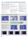
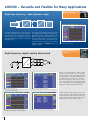
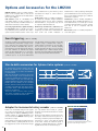
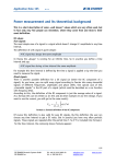
LMG500
Precision Power Analyzer
1 to 8 Channels • DC - 10 MHz • Accuracy 0.025 %
To develop, test and optimize
E-machines, frequency inverters, transfomers,
power electronics, power supplies, lighting
•
•
Bandwidth from DC and 0.05 Hz up to 10 MHz
•
Absolutely gapless sampling
•
LMG500 de 04/2012
Base accuracy of power 0.025 %
0.015 % of reading + 0.01 % of range
•
All samples being processed to capture all inrush currents,
signal spikes or drop-outs
Harmonics and interharmonics of up to 50 kHz in
realtime, up to 1 MHz post processed
LMG – A Synonym for Precision Power Measurement
Precision Power Meters (German: PräzisionsLeistungsMessGeräte) of the series LMG by ZES
ZIMMER – LMG95 for single phase, LMG450 and
LMG500 for multiphase measurements – are
well known world-wide and have been proved
invaluable in industrial applications, R&D and
education. The character string LMG has thus
become a synonym for precise and wideband
measurement of electrical power. All variables
linked with electrical power like current, voltage, harmonics, flicker and energy are also precisely determined for optimizing products in
efficiency, reliability, electromagnetic compatibility (EMC), and life-cycle costs.
The LMG500 is best-in-class for measurements
at:
• Devices, e.g. E-machines,
frequency inverters, transformers
• Installations and parts of those
• Power grids and consumers to determine interactions
• Components, e.g. ferrite cores,
semiconductors, capacitors
• 3 MSample/s per channel, absolutely gapless sampling with the evaluation of all sampling values
• Capturing transients and fast signal changes by event triggering in parallel to the ongoing Another application field are CE compliance
measurement
• Group delay between voltage and current
tests on devices, analyzing the feedback of
harmonics and flicker (load variations) and
measuring input <3 ns as standard to ascertain
standby power consumption.
very precise measurements at low cosj and/or high frequencies
• Harmonics and interharmonics up to 50 kHz The most important features of the LMG500
internally, and up to 1 MHz with an external PC
are:
• Flicker, interactions between network and load
• Wide dynamic measuring range from 3 V to •
1000 V / 3200 Vpeak, 20 mA to 32 A / 120 Apeak Ergonomic user interface for easy, intuitive use of the power analyzer
in direct measurement only by a single pair • Real-time evaluation of the measurements in of sockets for each voltage and current input
numeric tables and diagrams
• Modular with 1 to 8 power measuring • Data communication interfaces with high channels
transfer rates (RS232, USB, IEEE488.2, Ethernet)
• Measuring accuracy at 45 to 65 Hz 0.015 % of reading plus 0.01 % of range
Easy device settings and intuitive results display
Global settings, shown here is the
star-to-delta conversion
Independent setup of synchronization filter
and measurement path filter
Selection of input, scaling and measurement range
Different display modes for result in
numerical and graphical formats
Status bar for overviewing the running measurement
•A status bar is permanently displayed in
all menus
•Measurement display for one or four power channels, alternatively with six or 20 values, 40 values and more with scroll bars
• Global settings
•Two independent filter sets for the synchronization and the measurement path
•Choice of manual or automatic setting of the measurement ranges
Measurement display with six values
Graphical display for wave form
2
Line plot (trend display)
Vector diagram
Measurement display with 20 values
Parallel display of harmonics as bar graphs
Measuring inputs for ultimate requirements
• Current inputs I*, wide dynamic range:
20 mA to 32 A / 120 Apeak by only one
socket pair.
• Separated HF current inputs IHF*:
150 mA to 1.2 A / DC to 10 MHz
• No need for changing external shunts!
• Voltage inputs U*:
3 V to 1000 V / 3200 Vpeak
• Measuring with external sensors:
Inputs ISensor and USensor
30 mV to 4 V / DC to 10 MHz
• Auxiliary voltage ±15 V and
identification of external sensors
• Up to 8 power measuring channels with the compact 8-channel meter LMG500-8 or with two linked LMG500-4.
In both cases all channels are sampled gaplessly and synchronously with 3 MSamples/s.
• All input sockets are touch-proof, and isolated against each other and against earth (max. 1000 V / CAT III).
• High bandwidth of 10 MHz, hence very short pulses are measured precisely
• Very low capacity of measurement inputs against earth <30 pF, thus no distortion of measured signals
LMG-CONTROL – the LMG in your PC
LMG-CONTROL is the complementary PC software
for ZES ZIMMER power analyzers to configure the
instrument and to display, log and analyze the
measuring values.
Modifications to the setup of the LMG are immediately active. The multi-window implementation
permits displaying the measurement in multiple
ways at the same time.
Saving and loading of the instrument configuration along with the software settings in a single
project file permits easy repeating of a measuring task.
On demand LMG-CONTROL creates a report with
the configuration settings and the current
measuring values. This status report is particularly useful for remote diagnosis for the user and
the ZES ZIMMER support team.
The wave form analysis module (order-no. LMGControl-WA) extends the LMG with valuable features like frequency analysis and harmonics of up
to 1 MHz as well as the calculation of electrical
values within an adjustable frame and the display of transients with a resolution down to
330 ns.
3
LMG500 – Versatile and Flexible for Many Applications
Solar technology
High base accuracy – wide dynamic range
MPPT
I
I
DC
DC
Solar cell
U
50/60HzMains
U
AC
DC
The high nominal accuracy of 0.025 % allows
for correct measuring of very low currents in
the 32 A range. This is essential in test environments which do not allow for measuring
gaps which inevitably occur when changing the
measuring range.
To operate a solar generator at its power generating optimum the maximum power point tracker (MPPT) varies the input resistance of the
MPPT converter unit matching the inner resistance of the photovoltaic cell. The resistance is
continously changed by a small fraction optimizing the energy production under changing
weather conditions. The LMG500 tracks such
changes precisely.
High-frequency signals exactly determined
AC
I2
U4
Power electronics
Inverters
I1
I4
~
Voltage, current and effective power highly precise
without range switching
AC
I3
U1
U2
U3
M
n, Mn
Due to the high bandwidth of 10 MHz, highfrequency current peaks at the frequency
inverter output can be successfully sampled.
The combination of 4 measuring channels exactly determines the efficiency of an inverter.
Each switching edge is the cause for a transient current peak, being conducted through
the coil capacitance. The custom display shows
that Ipp is a magnitude higher than Itrms.
Extra-high current peaks at
simultaneous switching edges
Custom display with Ipp and Itrms
Voltage peaks through reflection may occur
on long connection cables between frequency
inverter and motor. They attain up to the twofold of the transmitted voltage pulse and put
additional strain on the cable isolation.
Voltage at inverter output as well as voltage and
current at motor with long connection cables
4
Easy to recognize: The peak value Upp doubles
Chokes
Transformers
Ultrasound
Precise measurements at low power factors
To increase the efficiency of contemporary PWM
frequency inverters, fast switching semiconductors are used for minimizing the switching
losses in the output stage. However, the extremely steep voltage edges cause capacitive currents that stress bearings and isolation of the
motors – this causes unnecessary wearing and
possibly an early break down.
Motor filters (e.g. du/dt-filters) attenuate the
voltage edges in rise and fall, but generate
power losses by the filters’ transient oscillations (typ. >100 kHz).
Power measurement up to 10 MHz demands
that current and voltage channels are designed
in a way that the delay between each other is
very small. With the LMG500 this delay is less
than 3 ns, or equal to an angle error <1 μrad at
50 Hz. Due to this feature the LMG500 is best
suited to measure the power losses of trans-
formers, chokes, capacitors and ultrasonic generators at very low power factors. The instrument
with the standard factory settings is already
fully sufficient for this kind of measurements.
Additional options or adjustments are not necessary. If needed, however, a calibration protocol (order no. KR-L50-LPF) to confirm the
measurement accuracies at power factors in
the range of 0.01 is available on request.
Usually current or voltage transducers are used
for measuring power transformers. The phase
angle error of these transducers can be compensated in the delay time menu (see p. 9)
improving the accuracy of the measurement.
A number of standards, like IEC 60076-1, define
the calculation of the corrected power. With
the build-in formula editor this is easily being
performed.
L-L voltage U4 before the filter,
voltage U1 across the filter and filter input current I1
U1
U2
AC
~
U4
AC
AC
du/dt Filter 1
I1
I2
du/dt Filter 2
I3
du/dt Filter 3
M
~
AC
I1
du/dt Filter 1
I5
I2
du/dt Filter 2
I6
I3
du/dt Filter 3
I7
U3
Power loss by measurement across the filter
Wave forms of current and voltage
U2
U3
U5
U6
U7
Power loss by difference measurement before and behind the filter
Ground capacitance <30pF
Due to the low ground capacitance of the
LMG500 measuring inputs <30 pF pulsed currents and voltages can be measured directly
and displayed distortion-free. The figures below
show the 70 kHz pulses (Upp = 2.5 kV, Ipp = 2.7 A)
required for maintaining the plasma of the gas
U1
M
Lighting technology
discharge flat lamp (light tile). Because of the
very small group delay between the voltage
and current channel, the power consumption is
calculated correctly despite these challenging
signals.
Custom menu with numerical results
5
LMG500 – Compact with up to 8 Channels
For some complex measuring situations 4 power measuring channels do not suffice and therefore the LMG500 with its up to 8 channels is the
superior choice. Regardless whether you use the compact 8-channel analyzer LMG500-8 or connect two LMG500-4 to collaborate like one device,
all channels operate always with gapless, synchronized sampling at 3 Msamples/s for each channel. The examples below demonstrate characteristic
measuring tasks which require 8 power measuring channels.
UPS
Wind generators
Determination of efficiency in complex systems
L1
A
I1
L2
L3
N
A
U1 V U2 V U3 V
3
f=50Hz
I2
A
I4
A
I8
A
DC
A
I4-I8
U4 V
I3
1
A
U8 V
U5 V U6 V U7 V
3
f=50Hz
DC
I5
I6
2
A
I7
3
n
Uninterruptible power supply with intermediate DC link
Pmech
3Ø, 3 Wire
2 Watt Meter
G
~
3Ø, 3 Wire
2 Watt Meter
3Ø, 3 Wire
2 Watt Meter
Pstator
Protor
Pmains
3Ø, 3 Wire
2 Watt Meter
DC
AC
DC
Wind generators without gear-box and extended range for the revolution speed: By keeping the frequency for the stator fixed and by
varying the rotor frequency, the double fed
asynchronous generator works with high
efficiency at very different wind speeds.
AC
Stator power, rotor power, mains power, and mains specific inverter power
each measured with the two watt meters (Aron circuit)
Three-winding
Transformers
Measurements with defined phase references
A three-winding transformer with two output
coils electrically shifted by 30° feeds two
6-pulse rectifiers. In doing so the primary
winding suppresses harmonics, e. g. the 5th,
7th, 17th and 19th.
The power measurement channels are configured as two groups with channels 1 and 5 in
parallel. This defines for all measurement
channels the same phase reference and allows
precise measurements for these kinds of special rectifier transformers with (nx30°) shifted
phase angles.
Mains
Rectifier
u2
u1
U1
U5
v1
w1
v2
w2
U2
U3
u3
v3
w3
U6
U7
8-channel measurement at 12-pulse rectifier transformer
6
U4
U8
Hybrid
automotive drives
8 power measurement channels plus
auxiliary inputs for rotation and torque
1. The car is moved by the combustion engine with or without receiving an addi-
tional boost from the inverter-fed 3-phase electrical machines M1 and M2
An LMG500-8 with its 8 power measurement
channels and the process signal interface for
torque and speed captures all data synchronously to precisely determine the efficiency
1 Phase
3 Phases
3. Recharging of the battery by the combustion engine
of each component. Additional trigger inputs
and outputs (not shown in the diagram)
allow the synchronization with other instruments in large test environments.
1Ø, 2Wire
1 Watt Meter
Inv 1
DC
3Ø, 3Wire
3 Watt Meter
AC
M1
Combustion engine
Transmission
DC
Accu
1Ø, 2Wire
1 Watt Meter
AC
Inv 2
1 Phase
2. Recuperation of the braking energy back into the battery
3 Phases
Optimization of the energy management of
hybrid automotive drives by analyzing the
power flow in various operation modes and
conditions:
M2
3Ø, 3Wire
3 Watt Meter
Measuring different drive modes in a hybrid car
7
LMG500 – Supplementary Features for Versatile Operations
Gapless data acquisition for long-term measurements
Benchmarks like SPECpower_ssj2008 and software suites as the Intel® Energy Checker have
been set up to relate the power consumption of
PCs and servers to their computing power. The
LMG500 is one amongst only a few power
meters being registered for both tests.
Standby consumption of domestic appliances is
covered by standards like IEC 62301. Depending on the product, parameters like efficiency,
consumption and standby performance have to
be measured. For example, minimum energy
efficiency is set for electric motors and lamps.
SPECpower
Energy label
For television sets and refrigerators, the maximum power input is defined depending on the
size of the screen or the cooling capacity.
Such tests require test times of several hours
and demand absolutely gapless data acquisition. The high base accuracy allows for sufficiently precise measurements even at the low
end of a measurement range, without switching
to the next range (see also application note
no. 102 “Measurement of standby power and
energy efficiency” available for download at
www.zes.com).
Scripting for automated calculation
Magnetic materials
I
˜
U
Circuitry
Scripting gives users the opportunity to calculate within the power analyzer own additional
values and shows them in a customized menu.
The script can either be edited in the device,
with or without an attached PS/2 keyboard, or
more conveniently written on a PC and downloaded with the aid of LMG-CONTROL.
A good example is the measurement of the
characteristics of magnetic cores. The power
Script editor
measured with the exciting current I and the
induced voltage U at the sensor winding (core
magnetization voltage) directly yields the core
losses depending on frequency of up to 10 MHz
without the copper losses. With the rectified
value of the sensor voltage U – a measure for
the voltage-time area and therefore the induced
flux – the exciting current I and the geometric
core data, the characteristic curves P (Bpk) and
Monitoring Harmonics with LMG-CONTROL
Harmonic analysis by ZES ZIMMER software
LMG-CONTROL
8
The spectral analysis of currents and voltages from DC to 1 MHz is supported by the
ZES ZIMMER application software LMG-CONTROL.
The results can also be exported as tables, e. g.
into MS Excel for further processing.
Harmonic analysis with LMG-CONTROL ranges up
to 1 MHz. The fundamental can be user-defined
from 0.07 Hz to 1 MHz.
Custom menu with numerical results
Bpk (Hpk) can be generated. With the high-performance script editor the respective curve
points are calculated measuring cycle by measuring cycle.
Please refer also application note no. 108 „Programmer’s Guide“ and no. 109 „Measurement of
magnetic characteristics of transformer cores
and coil materials“ at www.zes.com.
Avionics
The on-board power supplies of modern large
scale aircraft use power distribution systems with
frequencies of up to 800 Hz. Basic standards like
EUROCAE ED-14D and ABD0100.1.8 have been
created to define limit values. Fundamental frequencies from 360 Hz to 800 Hz must be assessed
by their harmonics in ranges up to 150 kHz.
Clustered measurement channels – each with independent synchronization
Up to eight power measurement channels,
each of them sampling absolutely synchronously with 3 MSamples/s, are possible with
a coupled second device or
• the compact 8-channel meter LMG500-8.
•
The current and the voltage paths of the
power measurement channels are all isolated
against each other and against earth. The
channels are arranged in up to 4 groups (see
table): channels 1 to 4 (device 1) into groups
A and B and channels 5 to 8 (device 2) into
groups C and D. The synchronization source
internal, external or “line” and the setup are
for each group independently configurable.
Channel no.
1
2
Group
formation
Possible
wiring in
the groups
A to D
A
3
4
5
B
C
4Ø 4Wire
4Ø 5Wire
1Ø 2L
1Ø 2L
1Ø 2L
1Ø 2L
3Ø 3Wire
3Ø 4Wire
1Ø 2L
4Ø 4Wire
3Ø 3L (Aron)/2Ø 3L 3Ø 3L (Aron)/2Ø 3L
3Ø 3L (Aron)/2Ø 3L
1Ø 2L
1Ø 2L
The settings of groups A and B for certain
wirings are independent to the settings of
6
7
8
D
4Ø 4Wire
4Ø 5Wire
1Ø 2L
1Ø 2L
1Ø 2L
1Ø 2L
3Ø 3Wire
3Ø 4Wire
1Ø 2L
4Ø 4Wire
3Ø 3L (Aron)/2Ø 3L 3Ø 3L (Aron)/2Ø 3L
3Ø 3L (Aron)/2Ø 3L
1Ø 2L
1Ø 2L
groups C and D. By the 4 groups 4 independent harmonic analyses can be performed.
Menu to compensate the delay time
of external sensors
Currents >30 A are measured with external sensors. For currents of more than 100 A, wideband
(>100 kHz) current transducers, e.g. of the
type PSU, are used. The error caused by the
group delay of the current transducer can be
compensated with the assistance of the delay
time menu by inserting the necessary time
adjustment. By doing so the precision of the
power measurement can be kept on a very high
level especially at low power factors.
Delay time menu with compensation values for I
in phase 1, 2 and 3
An outstanding tool with an easy-to-use menu.
CE-compliance test systems
CE-Test61k test system in a compact 19“ cabinet
Standby power
Harmonics and flicker
CE-Test61k
The ZES ZIMMER CE-Test-Standby test software
in combination with the LMG500 offers monitoring the power consumption in standby mode of
home appliances, IT devices and similar equipment in accordance to IEC/EN 62301. The results
are finally presented in a test protocol.
The compliance test system CE-Test61k allows
to test product interferences towards the power
distribution system caused by current harmonics and flicker in accordance with EN
61000-3-2/-12 and EN 61000-3-3/-11.
System characteristics:
• harmonics analyzer
- according to EN 61000-4-7 up to 2 kHz
- according to EN 61000-4-7 annex B
from 2 kHz to 9 kHz
• flicker meter according to EN 61000-4-15
Valuation:
• harmonic analysis for currents up to 16 A in compliance with EN 61000-3-2
• harmonic analysis for currents from 16 A
to 75 A in compliance with EN 61000-3-12
• flicker (voltage fluctuation) for currents
up to 16 A in compliance with EN 61000-3-3
• flicker (voltage fluctuation) for currents
up to 75 A in compliance with EN 61000-3-11
The system consists of:
ZES ZIMMER power analyzer LMG500
AC source, optionally the customer may use own sources
• reference impedance (for EN 61000-3-3)
• standards-compliant measuring and
analysis software
• PC or notebook
•
•
Delivery turnkey in a 19“ cabinet or as hardware/
software package for system integration by the
customer.
CE-Test-Standby,
display of a test in progress
Please refer to the detailed product description for
both products at www.zes.com.
9
Options and Accessories for the LMG500
IEEE488 interface (order no. L50-O1): Interpretation of the complete SCPI, as well as the
LMG500 specific command set. The data transfer
rate is up to 1 MByte/s.
editor, variables like e.g. the efficiency can be
calculated and output as control values to
other devices.
USB interfaces (order no. L50-O2USB): Front
side USB-A interface for the connection of a
memory stick and back side USB-B interface for
data transfer and remote control software.
Flicker meter (order no. L50-O4): Compliant to
EN 61000-4-15. Evaluates voltage fluctuations
induced by currents of up to 16 A in compliance
with EN 61000‑3‑3, or by currents of up to 75 A
in compliance with EN 61000-3-11.
Processing signal interface, digital and analog
in- and outputs (order no. L50-O3): For monitoring additional process parameters like rotation
speed, torque etc. With assistance of the script
Harmonics up to 99th for U, I, P, Q und S (order
no. L50-O8): Current, voltage and power are
analyzed up to 50 kHz with a fundamental between 0.1 Hz and 1.2 kHz. Evaluation of
Event triggering
CE harmonics (order no. L50‑O9): Compliant to
measurement device standard EN 61000-4-7, up
to the 40th harmonic, for currents up to 16 A in
compliance with EN 61000-3-2, and for currents
from 16 A to 75 A in compliance with EN
61000-3-12.
DSP modules (order no. L50-O10): Required for
some other options.
(order no. L50-O5)
Set trigger conditions are evaluated during the
normal measuring mode. When a trigger condition is met the scope display will be “frozen“
(shown as “Finish“ in the status bar). The normal measuring proceeds without any interruption and continues to evaluate all sample
values. For the sample values u, i, p from different measuring channels, up to four trigger
conditions (T1, T2, T3, T4) can be defined and
logically linked. A trigger condition can be that
a value is larger or smaller than a limit, or
inside/outside of a window, for an event duration of 330 ns up to 10 s. The fast sampling
captures all peaks and dips. For pre- and postevent analysis up to 2 million samples around
the event can be transmitted via the data interface and processed with external software.
Condition menu for event triggering
Star-to-delta conversion for 3phase-3wire systems
In 3phase-3wire systems usually only the
line-to-line voltages U 12, U 23 and U 31 and
the line currents I1, I2 and I3 are available
for measurement.
With the star-to-delta conversion option the
line-to-line voltages can be converted to the
not directly available phase voltages (line-toneutral voltages of the star-connected load)
and the related active powers can be revealed.
Likewise the line currents can be converted
into the „linked” currents (line-to-line currents
of a delta-connected load). From those calculated „linked” values, other magnitudes like the
harmonics are deduced.
The star-to-delta conversion works correctly
even under circumstances such as unbalances
of grid or load and distorted wave forms.
L1
I12
U2
U1
I2
L2
U23
L3
U31
I3
U3
I31
I23
3phase-3wire system: measurement of line-to-line voltages and line currents
Adapter for incremental rotary encoder
Pulses of an incremental rotary encoder (signal
u2 in cyan) are transformed into a proportional
voltage with the adapter L50-Z18 (positive/
negative voltage for forwards/backwards) and
are connected to the LMG500 measuring input,
here the ISensor input.
In the example on the right, the status bar shows
the status “Finish”, signaling that the set event
has triggered. Also shown are the motor voltage
(order no. L50-O6)
I1
U12
Calculated values (linked values) of the star-connected
windings (wiring: 3+1, UΔ I* → U*I*)
10
interharmonics is made possible by dividing the
given fundamental to a lower one using it as reference. For the harmonic analysis up to 1 MHz an
external PC is recquired.
Calculated values (linked values) of the delta-connected
windings (wiring: 3+1, UΔ I* → UΔ IΔ)
(order no. L50-Z18)
(u1 - red) and the motor current (i1 - yellow).
The latter rises with the electrical time constant
of the rotor.
About 0.7 ms after applying current to the motor,
the rotation starts and is shown by the rise of
the analog, revolution-proportional adapter output signal (i2 - green). 3.5 ms after the startup
of the motor current, the rotational speed of
126 U/min is already determined. It is noteworthy that the rotor has so far turned only 8°.
Rotary encoder output via adapter L50-Z18
connected to a measurement channel to record a
fast motor start with high resolution
Technical Data (Summary)‡
Voltage measuring ranges U*
Nominal value /V
Maximum trms value /V
Maximum peak value for full scale /V
Input impedance
Current measuring ranges I*
Nominal value /A
Maximum trms value /A
Maximum peak value for full scale /A
3
3,6
6
6
12,5
7,2
14,4
12
25
>4,5MΩ || <3pF
20m
37m
56m
Input impedance
Sensor inputs USensor, ISensor
Nominal value /V
Maximum trms value /V
Maximum peak value for full scale /V
Input impedance
40m
75m
112m
80m
150m
224m
25
30
50
60
66
100
130
136
200
250
270
400
400
560
800
600
999
1600
1000
1001
3200
150m
300m
469m
300m
600m
938m
600m
1,25
1,88
1,2
2,5
3,75
2,5
5,0
7,5
5
10
15
10
20
30
710mΩ
30m
37m
62m
84mΩ
60m
120m
75m
150m
125m
250m
100kΩ || 34pF
250m
300m
500m
500m
600m
1
27mΩ
1
1,2
2
Measuring accuracy
2
2,5
4
Current measuring ranges IHF*
150m
300m
600m
1,2
225m
450m
900m
1,8
313m
625m
1,25
2,5
8,4mΩ
100mΩ
4
5
8
0.02+0.06
0.05Hz..45Hz 45Hz…65Hz 65Hz…3kHz 3kHz…15kHz 15kHz…100kHz
0.02+0.03
0.03+0.06
1MHz…3MHz
3MHz…10MHz
0.5+1.0
3+3
f/1MHz*1.2 + f/1MHz*1.2
0.4+0.8
0.4+0.8
f/1MHz*0.7 + f/1MHz*1.5
f/1MHz*0.7 + f/1MHz*1.5
0.5+1.0
0.5+1.0
f/1MHz*1 + f/1MHz*2
USensor
0.02+0.06
0.015+0.03
0.01+0.02
0.015+0.03
0.03+0.06
0.2+0.4
I* (20mA ... 5A)
0.02+0.06
0.015+0.03
0.01+0.02
0.015+0.03
0.03+0.06
0.2+0.4
I* (10A ... 32A)
0.1+0.2
0.3+0.6
f/100kHz*0.8 + f/100kHz*1.2
IHF*
0.03+0.06
0.03+0.06
0.2+0.4
0.2+0.4
0.015+0.01 0.028+0.03 0.048+0.06
0.104+0.13
0.1+0.2
500kHz…1MHz
Current
0.032+0.06 0.028+0.03
0.02+0.03
0.5+1.0
U*
U* / I* (10A ... 32A)
0.01+0.02
100kHz…500kHz
Voltage
Power
32
32
120
± (% of measuring value+ % of measuring range)
DC
ISensor
U* / I* (20mA ... 5A)
20
32
60
0.24+0.3
0.32+0.4
-
-
0.5+1.0
0.4+0.8
0.5+1.0
0.4+0.8
f/1MHz*1 + f/1MHz*2
f/1MHz*0.7 + f/1MHz*1.5
0.8+1.0
0.8+1.0
f/1MHz*3.2 + f/1MHz*2.5
f/100kHz*1 + f/100kHz*1.1
-
-
f/1MHz*0.7 + f/1MHz*1.5
-
U* / IHF*
0.048+0.06
0.24+0.3
0.8+1.0
0.8+1.0
f/1MHz*3.2 + f/1MHz*2.5
-
U* / ISensor
0.048+0.06
0.24+0.3
0.72+0.9
0.72+0.9
f/1MHz*3 + f/1MHz*2.3
f/1MHz*1.5 + f/1MHz*1.4
0.024+0.03 0.048+0.06
0.32+0.4
0.72+0.9
0.72+0.9
f/1MHz*1.4 + f/1MHz*1.8
-
USensor/ I* (10A ... 32A)
USensor / I* (20mA ... 5A)
0.024+0.03
0.104+0.13
0.40+0.5
f/100kHz*1 + f/100kHz*1
-
-
-
USensor / IHF*
0.048+0.06
0.32+0.4
0.72+0.9
0.72+0.9
f/1MHz*1.4 + f/1MHz*2
-
USensor / ISensor
0.048+0.06
0.32+0.4
Additional measurement uncertainty
Accuracies based on:
Other values
Isolation
Synchronization
Harmonic analysis for
CE compliance (option L50-O9)
Harmonic analysis up to
99th harmonic (option L50-O8)
Flicker measuring (option L50-O4)
Transients (option L50-O5)
Scope function (standard)
Plot function (standard)
Computer interfaces
Remote control
Output data
Transfer rate
Processing signal interface
(option L50-O3)
Other data
Dimensions / weight
0.64+0.8
0.64+0.8
in the ranges from 10 A to 32 A: ± (I trms)² • 30 μA / A²
f/1MHz*1.12 + f/1MHz*1.5 f/1MHz*1.12 + f/1MHz*1.5
1. sinusoidal voltage and current
4. definition of power range as the product of current and voltage range,
2. ambient temperature (23 ± 3) °C
0 ≤ |λ| ≤ 1 (λ=power factor=P/ S)
3. warm up time 1 h
5. calibration interval 12 months
All other values are derived from the current, voltage and active power values. Accuracies for derived values depend on the functional relationship
(e.g. S = I * U, ΔS / S = ΔI / I + ΔU / U)
All current and voltage inputs isolated against each other, against remaining electronic and against earth
max. 1000 V / CAT III resp. 600 V / CAT IV
The measurement is synchronized on the signal period. There is a choice to determine the period from “line“, “extern“, u(t), i(t) as well as their envelopes, combined
with settable filters. By this very stable readings are achieved, even at signals of pulse width modulated frequency inverters and amplitude modulated electronic ballasts.
Measuring of current and voltage with evaluation in full compliance with EN 61000-3-2/-12,
measurement according to EN 61000-4-7
Analysis of current, voltage (incl. phase angle) and power up to 99th harmonic, in total 100 harmonics including DC component. Fundamental in the range from
0.1 Hz to 1.2 kHz. Analysis up to 10 kHz (50 kHz without antialiasing filter). By integer divider (1...128) a new reference fundamental can be created to detect interharmonics. Externally on PC up to 1 MHz with LMG-CONTROL software.
Flicker meter according to EN 61000-4-15 with evaluation in full compliance with EN 61000-3-3/-11
Detecting and recording of transients >330 ns
Graphical representation of sample values versus time
Time (trend) diagram of max. 4 readings, minimal resolution 50 ms, respectively 10 ms in 50Hz-half-wave (flicker) mode
RS232 (standard) und IEEE488.2 (option L50-O1), additional USB 2.0 Type B (option L50-O2USB), Ethernet,
RJ45 (option LMG50-O2ETH). Only one interface can be used at the same time
All functions can be remote-controlled, keyboard lock for measuring parameters
Output of all readings, data formats BIN/ASCII, SCPI command set
RS232: max. 115200 Baud, IEEE488.2: max. 1 MByte/s
2 x 25 pin SUB-D socket with:
• 8 analog inputs for process data (24Bit, ±10V) (24Bit, ±10V), 8 analog outputs (14Bit, ±10V)
• 8 digital inputs, 8 digital outputs
• 2 inputs for frequency (0.05 Hz...6 MHz) and rotation direction
In- and outputs are isolated against other electronics (test voltage 500V).
Bench case 1 to 4 channels W 433 mm x H 148 mm x D 506 mm / about 12 kg
Bench case 1 to 8 channels W 433 mm x H 283 mm x D 506 mm / about 23 kg
• Accessories: brackets for 19‘‘ rack, 84 PU, 3 HU, D 464 mm
EN 61010 (IEC 61010, VDE 0411), protection class I / IP20 in accordance to EN 60529
EN 61326
0 ... 40 °C / -20 ... 50 °C
Normal environment conditions according to EN 61010
100 ... 240 V, 50 ... 60 Hz, max. 150 W (4-channel device) respectively max. 300 W (8-channel device)
•
•
Protection class
Electromagnetic compatibility
Operating / storage temperature
Climatic class
Power supply
‡
Please refer to the LMG500 user manual for all technical data.
11
Measurement Accessories and Extensions
„Plug N‘Measure“ current sensors
for extended current ranges up to 5000 A
For detailed specifications please refer to
the „ZES Sensors and Accessories“ manual.
(1) Precision current transducer
(2) Precision AC current transformer
(3) Clamp-on current sensor
(4) Wideband current transformer
(5) Hall effect current sensor
0.02 %
0.02 %
0.15 %
0.25 %
0.30 %
Example to (1):
Precision current transducers PSU700-L50 for 700 A
DC
15 Hz
2 Hz
30 Hz
DC
to
1 MHz
to
5 kHz
to 50 kHz
to
1 MHz
to 200 kHz
to 5000 A
to 1500 A
to 3000 A
to 1000 A
to 2000 A
Example to (2):
Precision AC current transformer LMG-Z502 for 1500 A
Example to (4):
Wideband current
transformer LMG-Z601 for 100 A,
30 Hz to 1 MHz
Precision high voltage divider
0.8 A
5 A
0.3 A
10 A
0.3 A
Example to (3):
Clamp-on current sensor
L45-Z06 for 40 A, 5 Hz to 20 kHz
Example to (5):
Hall effect current sensors
L50-Z29-Hall for 50 A to 1000 A
for 3/6/9/12 kV, DC to 300 kHz, base accuracy 0.05 %
Negligible phase error, therefore best suited for wideband
power measuring.
- 1-channel HST for single ended voltages
- 2-channel HST for floating voltages (difference measuring)
- 3-channel HST for three phases systems (inverters)
Adapter for 3-phase measurements
Order no. LMG-MAK3
Socket for supplying the meter LMG500/LMG450
4mm safety sockets as measuring access to current and voltage
• Safety acc. IEC 61010: 300 V / CAT III
• CEE-Plug, 5 pins, 16 A, 2 m supply cord
• CEE-Socket, 5 pins, 16 A, for EUT
•
•
M-n motor torque software
Order no. L50-O16
Torque and speed directly calculated from the current and voltage
at a motor compliant to the IEC standard that is powered by a
frequency inverter or directly by a 3-phase net. Accuracy better
than 2% of nominal value of torque respectively rotation speed.
Configurable with plugin in software LMG-CONTROL.
PC software
Order no. LMG-CONTROL-B
To configure power analyzers, recording and storage of samples, to
visualize data as list or diagram. Status report for the system diagnostics.
The basic version is free of cost.
Order no. LMG-CONTROL-WA
Additional module for LMG-CONTROL, logging and analysis of sample
values of the LMG, frequency spectrum and harmonic analysis up to
1 MHz, frame analyzer, logging of transients.
Calibration
Order no. KR-L50-B, KR-L50-CHN
Calibration with certificate, traceable according to ISO9000, basis
package and in addition for each power channel.
Calibration and service package
for extended warranty
Order no. L50-KSP
With the purchase of the calibration and service package, the
warranty can be extended every year for further 12 months.
A prerequisite is the calibration traceable according to ISO9000
at first delivery of the device. Every 12 months the device has
to be sent back to ZES ZIMMER for a further calibration and if
necessary for adjustment. Along with the calibration the
appropriate maintenance work is carried through. During the
warranty period and extended warranty period all incidental
repairs are free of charge. Repairs of failures by abrasion and
faulty handling are excepted from the warranty.
© 2011 - ZES ZIMMER Electronic Systems GmbH - subject to technical changes, especially to improve the product, at any time without prior notification.
Germany (headquarter)
ZES ZIMMER Electronic Systems GmbH
Tabaksmühlenweg 30 • D-61440 Oberursel
[email protected] • +49 6171 628750
www.zes.com
United States (subsidiary)
ZES ZIMMER, Inc.
44 Grandville Ave. SW • Suite 360
Grand Rapids • MI 49503-4064
[email protected] • +1 760 550 9371