1
LA2000 GEN. 2
Linear Servo Amplifier
USER’S MANUAL
Motion Control Systems, Inc.
New River, Virginia
http://www.motioncontrol.org/
1405260 Rev. D
Approved: MPW 2/9/10
MCS LA2000 GEN 2 AMPLIFIER USER'S MANUAL
Table Of Contents
Table of Contents
2
Part 1:
Important Safety Notices
4
Safety Notices / Avis de sécurité................................................................
Safety Ground / Prise de terre de sécurité..................................................
Hazardous Voltages Warning / Avertissement d’une tension dangereuse....
Life Support Policy / Politique de survie....................................................
Other Notices / Autres avis........................................................................
4
4
5
5
6
General
7
1.1
1.2
1.3
1.4
1.5
Part 2:
2.1
2.2
2.3
Part 3:
3.1
3.2
3.3
3.4
Part 4:
4.1
4.2
4.3
4.4
4.5
4.6
4.7
4.8
4.9
Introduction............................................................................................... 7
Warranty.................................................................................................... 7
Field Service.............................................................................................. 8
Installation
9
Unpacking.................................................................................................
Mounting...................................................................................................
Ambient Conditions...................................................................................
Air Flow Requirement................................................................................
9
9
10
10
Electrical System Wiring
11
Input Power............................................................................................... 11
4.1.1 Selecting Input Voltage.................................................................. 11
4.1.2 Input Voltage/Current Ratings........................................................ 11
Output Power............................................................................................. 12
4.2.1 Motor phasing (For Motors Manuf. by MCS)................................. 12
4.2.2 Motor phasing (For Motors not Manuf. by MCS)............................ 13
4.2.3 Motor Power Connection................................................................ 13
Motor Feedback (Commutation) Wiring..................................................... 14
4.3.1 Encoder-Only Wiring...................................................................... 14
4.3.2 6-Step HED Wiring (For Motors Manuf. by MCS)......................... 15
4.3.3 6-Step HED Wiring (For Motors not Manuf. by MCS).................... 15
Initial Adjustments...................................................................................... 15
4.4.1 Commutation Adjustment for Encoder-Only Systems...................... 16
4.4.2 Commutation Adjustment for Hall Effect + Encoder Systems.......... 17
Encoder Outputs........................................................................................ 18
Serial (RS-232) Communications Wiring.................................................... 19
USB and Ethernet Communications Wiring................................................ 19
Optional 20 Pin Ribbon / BDC Compatibility Connector............................. 20
Optional High Frequency PECL Connector / Aux PLL Option................... 20
PAGE 2
1405260 Rev. D
MCS LA2000 GEN 2 AMPLIFIER USER'S MANUAL
Part 5:
5.1
5.2
5.3
Part 6:
6.1
6.2
Part 7:
7.1
7.2
Part 8:
8.1
8.2
Part 9:
9.1
9.2
Part 10:
User Interface
21
Software Interface...................................................................................... 21
5.1.1 Command Definition....................................................................... 21
5.1.2 Command Summary........................................................................ 21
5.1.2.1 Commands for “Normal” Mode........................................... 21
5.1.2.2 Commands for “Configuration” Mode................................. 28
Hardware Interface..................................................................................... 33
5.2.1 TTL Interface................................................................................. 33
5.2.2 Analog Interface............................................................................. 33
5.2.3 Analog Interface (Velocity mode control) ...................................... 33
Error Messages and Their Meanings........................................................... 34
Operation
35
Power Up................................................................................................... 35
Normal Operation....................................................................................... 36
6.2.1 Communications-Controlled Systems.............................................. 36
6.2.2 Interlocks and Faults....................................................................... 36
Theory of Operation
38
Control Section.......................................................................................... 38
7.1.1 FLL Velocity Control Loop............................................................ 38
7.1.2 Commutation Section..................................................................... 39
7.1.3 Motor Phase Current Control Loop Section.................................... 39
Power Section............................................................................................ 39
Servicing
40
Maintenance .............................................................................................. 40
Troubleshooting ........................................................................................ 40
Specifications
43
General ..................................................................................................... 43
Connector Definitions................................................................................ 43
9.2.1 SC-5: RS-232 Serial Connector...................................................... 43
9.2.2 SC-2: Commutation (Motor Feedback) Connector.......................... 44
9.2.3 Motor Power Connector................................................................. 44
List of Drawings
List of Options
45
46
PAGE 3
1405260 Rev. D
MCS LA2000 GEN 2 AMPLIFIER USER'S MANUAL
Part 1
IMPORTANT SAFETY NOTICES
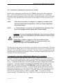
1.1
Safety Notices / Avis de sécurité
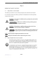
The following conventions are used to illustrate important safety information in the manual.
Les conventions suivantes sont utilisées pour illustrer les informations de sécurité importantes
contenues dans le manuel.
F
WARNING: Alerts reader of conditions and/or procedures that could result in
personal injury or death.
!
CAUTION: Calls attention to conditions and/or procedures which, if not
followed, can result in permanent damage to equipment.
AVERTISSEMENT : Indicateur de conditions et/ou de procédures pouvant
entraîner des préjudices corporels ou la mort.
ATTENTION : Attire l’attention sur des conditions et/ou des procédures qui, si
elles ne sont pas respectées, peuvent entraîner des dommages permanents aux
équipements.
NOTE: Points out useful or important information to the reader.
NOTE : Souligne des informations utiles ou importantes pour le lecteur.
1.2
Safety Ground / Prise de terre de sécurité
This product must be grounded. The power cord supplied with the product is for
115 VAC outlets. If the user wishes to provide a different cord for 230 VAC, the
cord must have a ground connection. In addition, any device (e.g. motor, control
device, etc.) connected to this system must be grounded.
Ce produit doit être mis à la terre. Le cordon d’alimentation fourni avec le produit
est conçu pour les prises 115 V CA. Si l’utilisateur souhaite utiliser un cordon
différent adapté à une alimentation 230 V CA, ce dernier doit pouvoir être relié à la
terre. Par ailleurs, tout élément (par exemple, moteur, dispositif de commande, etc.)
connecté à ce système doit être mis à la terre.
PAGE 4
1405260 Rev. D
MCS LA2000 GEN 2 AMPLIFIER USER'S MANUAL
F
1.3
AVERTISSEMENT : Tout fonctionnement sans une mise à la terre adéquate
peut entraîner un choc électrique potentiellement fatal. Tout élément accessible
(par exemple, boîtier, interrupteurs, etc.) et tout dispositif périphérique doivent
être considérés comme étant sous tension.
Hazardous Voltages Warning / Avertissement d’une tension dangereuse
F
F
1.4
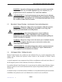
WARNING: Operation without proper grounding can result in a potentially
fatal electric shock. Any accessible component (e.g. case, switches, etc.) or
peripheral device is to be considered "live" under this condition.
WARNING: Dangerous voltages exist at several places within the enclosure.
Disconnect power before and during any disassembly or servicing. Only
qualified personnel should service this product.
AVERTISSEMENT : Des tensions dangereuses existent à différents
emplacements du site. Couper l’alimentation avant et pendant toute
manipulation ou toute opération d’entretien. Seul du personnel qualifié peut
assurer l’entretien de ce produit.
WARNING: Dangerous voltages exist at the motor power terminals when the
drive has power applied. Disconnect power and exercise caution when
connecting to these terminals.
AVERTISSEMENT : des tensions dangereuses existent au niveau des bornes
du moteur lorsque la transmission est alimentée. Couper l’alimentation et
rester vigilant lors de la connexion à ces bornes.
Life Support Policy / Politique de survie
Motion Control Systems, Inc. products are not authorized for use as critical components in life
support systems without the expressed written consent of the President of Motion Control
Systems, Inc.
A critical component is any component whose failure or malfunction could result in the failure of
the life support system or in the reduction of its safety or effectiveness.
Les produits Motion Control Systems, Inc. ne peuvent pas être utilisés comme éléments critiques
dans des systèmes de survie sans l'autorisation écrite expresse du président de Motion Control
Systems, Inc.
Un élément critique est un élément dont la défaillance ou le dysfonctionnement pourrait entraîner
la défaillance du système de survie ou la limitation de sa sécurité ou de son efficacité.
PAGE 5
1405260 Rev. D
MCS LA2000 GEN 2 AMPLIFIER USER'S MANUAL
1.5
Other Notices / Autres avis
F
!
WARNING: Do not operate this system in explosive atmospheres.
AVERTISSEMENT : ne pas utiliser ce système dans des atmosphères
explosives
CAUTION: The voltages applied to the LA amplifier must not exceed the
maximum stated voltages. (See Section 9.1)
ATTENTION : la tension appliquée à l’amplificateur LA ne doit pas excéder
les tensions maximum définies (voir la section 9.1).
F
!
WARNING: The AC input power is double pole/neutral fused.
N
AVERTISSEMENT : l’alimentation CA dispose d’un fusible
bipolaire/neutre.
CAUTION: See Part 9 for Fuse Ratings.
ATTENTION : Voir la Partie 9 pour le classement de fusible.
NOTE: This manual uses the terms "Amplifier", "Controller", “Motor Drive”, and
"Motor Controller" interchangeably.
NOTE : ce manuel utilise les termes « amplificateur », « contrôleur », « moteur » et
« commande moteur » de manière interchangeable.
PAGE 6
1405260 Rev. D
MCS LA2000 GEN 2 AMPLIFIER USER'S MANUAL
Part 2
GENERAL
2.1
Introduction
The LA2000 is a four quadrant velocity servo amplifier intended to control three phase permanent
magnet synchronous motors (commonly called brushless DC motors, since some of their
characteristics are similar to ordinary DC motors). The LA2000 motor controller uses a very
"quiet" linear power stage and is intended for applications where electromagnetic interference or
acoustical noise must be kept to a minimum.
Under normal operation, a brushless motor controller must "know" the position of the rotor in
order to commutate the motor to produce torque. The LA2000 obtains rotor position
information from a quadrature encoder or Hall Effect sensors. The LA2000 can also be
optionally configured, by MCS, to use an external commutation source with current requests fed
directly into the amplifier (known as Sine/Sine+120 operation).
Systems are intended for computer control through a high level command syntax. This feature
allows them to be easily integrated into computer controlled testing or manufacturing equipment.
For other applications, see Section 5.2 (Hardware Interface).
The motor controller unit is intended for cabinet or panel mounting. See Section 3.2, Mounting,
for a mounting diagram.
2.2
Warranty
Motion Control Systems, Inc. (MCS) warrants that all products it manufactures shall be free from
defects in materials and workmanship for a period of one (1) year from the date of shipment,
provided that such products have been subjected to proper and normal use, and further provided
that MCS receives written notice from the purchaser setting forth the nature and extent of the
defect within the warranty period. The obligations of MCS under this warranty are limited to, at
its option, the repair or replacement, free of charge, of any product covered by this warranty that
has been returned with prior written consent to MCS, or as it may direct, transportation charges
prepaid by the purchaser.
Motion Control Systems, Inc. (MCS) reserves the right to void this warranty at any time if any
product is altered, tampered with, modified, repaired or serviced by any unauthorized person or
company, without prior written approval from MCS.
MCS takes no responsibility for any damage to products if unauthorized alterations or
modifications were performed without prior written consent from MCS.
MCS shall, in no event, be liable for any breach of warranty in an amount exceeding the purchase
price, nor for any special, consequential, or incidental damages.
PAGE 7
1405260 Rev. D
MCS LA2000 GEN 2 AMPLIFIER USER'S MANUAL
This warranty is in lieu of any and all other warranties, expressed, implied, or statutory including
implied warranties of merchantability or fitness.
2.3
Field Service
Normal procedure requires that defective products be shipped prepaid and with prior written
consent to MCS for repair. However, under certain extreme circumstances and at the purchaser's
request, MCS can provide on site service. Contact the MCS sales department to arrange a service
visit. A purchase order must be issued and received by MCS prior to departure of MCS service
personnel.
PAGE 8
1405260 Rev. D
MCS LA2000 GEN 2 AMPLIFIER USER'S MANUAL
Part 3
INSTALLATION
3.1
Unpacking
Remove the unit from its shipping container. All units should be lifted and handled from the back
(mounting panel surface). Inspect the unit for shipping damage. Do not attempt to operate the
unit if it has been damaged, or if it has been configured improperly. Instead, call MCS.
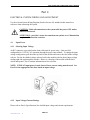
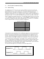
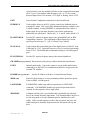
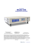
3.2
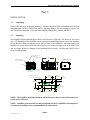
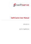
Mounting
The amplifier mounts through tapped holes on the bottom of the unit. The holes are for screws
size 8-32. Mounting is also available with an optional mounting flange on one end of the amplifier.
Do not block the front (air exhaust) or the side (air inlet) of the controller. All connections to the
amplifier are on the front on the unit, therefore be sure to leave enough room at the front of the
unit for wiring. Below is a diagram of the mounting hole locations. See Drawing #1405210 for a
more detailed drawing.
BDC COMPATIBILITY
CONNECTOR
11.000
[279.4 mm]
AC POWER/FUSE
MOTOR FEEDBACK
(SC2 COMMUTATION)
MOUNTING BRACKET
(OPTIONAL)
(5 1/2)
RS232
6.250
[158.8 mm]
AIR OUTLET
FRONT VIEW
POWER OUTPUT
TO MOTOR
BACK VIEW
AIR INLET
SIDE VIEW
6.030
[153.2 mm]
8X MOUNTING HOLES
1.930
[49.0 mm]
8-32 UNC-2B 1/4
7.250
[184.2 mm]
1.750
[44.4 mm]
3.370
[85.6 mm]
2.800
[71.1 mm]
Ø.218
[Ø5.5 mm]
2.100
[53.3 mm]
1.560
[39.6 mm]
6.030
[153.2 mm]
BOTTOM VIEW
.250
[6.4 mm]
.309
[7.8 mm]
NOTE: The amplifier should be mounted and positioned so that access to the main power
switch is not restricted.
NOTE: Amplifier protection devices may be impaired if the LA amplifier is not operated
or mounted according to the recommendations in this manual.
PAGE 9
1405260 Rev. D
MCS LA2000 GEN 2 AMPLIFIER USER'S MANUAL
3.3
Ambient Conditions
Select a location free of excessive dust, coolants, vibration, corrosives, condensation, flammable
materials, etc. Select a location having ambient temperature between zero and 40 degrees C, and
humidity between 5% and 80% (non-condensing). Although the motor controller is thermally
protected, ambient temperature should be kept as low as practical, since high temperatures can
degrade performance and reliability.
3.4
Air Flow Requirement
The motor controller has a built-in fan for cooling, which exhausts out of the front of the unit.
Do not obstruct the fan, or any other vents, as this may cause the unit to overheat. MCS
recommends maintaining at least 1” (2.54cm) minimum clearance around fan intake and air
exhausts.
PAGE 10
1405260 Rev. D
MCS LA2000 GEN 2 AMPLIFIER USER'S MANUAL
Part 4
ELECTRICAL SYSTEM WIRING AND ADJUSTMENT
Use the relevant System Wiring Diagram (listed in Section 10) included in this manual as a
reference when connecting the system.
!
4.1
CAUTION: Make all connections to the system with the power OFF, unless
otherwise instructed.
ATTENTION : procéder à toutes les connexions au système avec l’alimentation
coupée, sauf instruction contraire.
Input Power
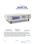
4.1.1 Selecting Input Voltage
An IEC connector is provided on the front of the unit for power entry. Units are field
configurable for 115/230 VAC operation through the power entry module. To change the input
voltage configuration, pull down the top latch of the module and remove the fuse holder/voltage
selector. Put the fuse holder/voltage selector back in the module with the desired input voltage
reading right side up through the window. Below is a drawing of the module with the latch
closed and opened. Part 9 contains information on fuse selection.
NOTE: If 230VAC input power is used, fuses of lower current rating must be used. See
Part 9 for the appropriate fuse sizes based on input voltage.
4.1.2 Input Voltage/Current Ratings
Please refer to Part 9 (Specifications) for detailed input voltage and current requirements.
PAGE 11
1405260 Rev. D
MCS LA2000 GEN 2 AMPLIFIER USER'S MANUAL
4.2
Output Power
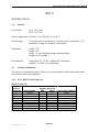
4.2.1 Motor Connections (for motors manufactured by MCS)
Motors manufactured by MCS will have leads that are colored or coded as follows:
Wire
Color
White
Black
Red
Phase
Name
Phase W
Phase V
Phase U
Some motors manufactured by MCS will have all phase windings available for connection. In this
case, the motor has six leads; two per phase. This permits the windings to be connected in either
wye or delta connection. Such a motor will have its leads labeled as 1F, 1S, 2F, 2S, 3F, and 3S.
WYE
AMP
W
V
U
MOTOR
Phase W: 3S
Phase V: 1S
Phase U: 2S
Connect 1F + 2F + 3F together
DELTA
AMP
W
V
U
MOTOR
Phase W: 2F + 3S (connect together)
Phase V: 3F + 1S (connect together)
Phase U: 1F + 2S (connect together)
PAGE 12
1405260 Rev. D
MCS LA2000 GEN 2 AMPLIFIER USER'S MANUAL
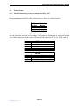
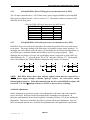
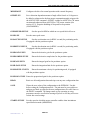
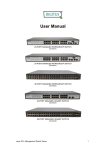
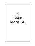
4.2.2 Motor Connections (for motors not manufactured by MCS)
Designate the motor leads as "U," "V," and "W" such that the sequence U-V-W causes CW
(clockwise) rotation of the motor shaft when looking at the motor from the non-lead side. The
lead side is the side of the motor at which the motor lead wires exit. If you view the motor output
voltages (Back-EMF) of the motor while it is disconnected from the controller and spun
clockwise by hand, the output on an oscilloscope should look as follows:
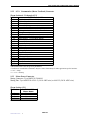
4.2.3 Motor Power Connection
The power to the motor is supplied through a CPC plastic connector on the front panel. This
connector is intended for connection to three-lead motors. The following table shows the pin out
for the motor power connector.
Motor Power Connector
Pin #
1
6
8
14
3-LEAD MOTOR
Phase Name
Phase W
Phase V
Phase U
GROUND
Mating Connector: Tyco/AMP P/N: 206044-1
Mating Pins: Tyco/AMP P/N: 66361-2 (14-18 AWG wire) or 66103-2 (20-24 AWG wire)
PAGE 13
1405260 Rev. D
MCS LA2000 GEN 2 AMPLIFIER USER'S MANUAL
4.3
Motor Feedback (Commutation) Wiring
4.3.1 Encoder Wiring
The amplifier has a 5V, 250 mA (max) power supply available for powering an encoder (and
motor Hall Effect Devices – refer to section 4.3.2). The encoder connects to connector SC2 on
the front of the unit. Connections are shown below in the table. The LA2000 can accept
differential or single-ended TTL or 5V CMOS level encoder signals. An MCS-installed option is
available for use with a sinewave output (analog) encoder. Contact MCS for more information on
this option, if needed. Use an encoder with differential outputs whenever possible, to reduce the
effects of ambient electromagnetic interference. If a single-ended output encoder is used, treat the
A-, B-, and INDEX- inputs as “No Connect” pins. Use the CONFIG? command to determine if
your system is configured for single ended or differential inputs. See Section 5.1.2.2 Commands
for the Configuration Mode, if you need to change the configuration.
Encoder Connections Table
+5V Supply
Encoder Channel A+
Encoder Channel B+
Encoder Index +
Logic Common
Encoder Index Encoder Channel AEncoder Channel BShield
1
2
3
4
9 or 25
12
20
21
24
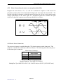
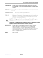
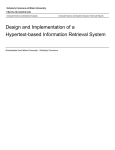
To determine the correct convention of the A and B inputs, apply power to the encoder and rotate
the shaft or rotor in the CW direction, as viewed from the end of the motor opposite the motor
lead exit. The A input should lead the B input by transitioning from 0 to 1 while B is at 0. To
determine whether the system is set up properly, rotate the motor in the CW direction. While the
motor is rotating, issue the DIR? command to the serial interface. If the system responds with
"CW" then the encoder is wired properly. If it responds "CCW," switch the encoder A and B
inputs. It is important that the command is issued while the spindle is rotating smoothly, because
the motor momentarily reversing could result in the wrong status reported back. For LA2000
drives that do not have the optional BNC encoder outputs, a breakout fixture can be connected to
the SC2 connector to view the A and B encoder channels.
The correct encoder outputs for CW rotation (as viewed at the input of SC2):
PAGE 14
1405260 Rev. D
MCS LA2000 GEN 2 AMPLIFIER USER'S MANUAL
4.3.2
6-Step Hall Effect Device Wiring (for motors manufactured by MCS)
The LA motor controller has a 5 volt, 250mA (max.) power supply available for powering Hall
Effect sensors (and an encoder – refer to section 4.3.1). The sensors connect to connector SC2
(DB25M) on the front panel.
6 Step Hall Effect Wiring Connections (for MCS motors)
DESIGNATION
+5V Supply
Logic Common
Hall Sensor 1
Hall Sensor 2
Hall Sensor 3
Shield
4.3.3
WIRE COLOR SC-2 PIN #
Red
1
Black
9 or 25
Yellow
15
Green
16
White
17
---24
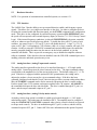
6-Step Hall Effect Convention (for motors not manufactured by MCS)
Hall Effect devices are used by the controller to determine the position of the rotor with respect
to the stator. The proper phasing of the Hall sensors is essential to proper motor operation. To
determine the correct phase, rotate the motor CW and display the waveforms described below on
an oscilloscope to determine whether the Hall Effect devices are properly phased. When
displaying the waveforms on a scope, the second phase shown is connected to probe GND (e.g.,
when displaying “W – V”, place the probe TIP on “W” and probe GND on “V”). The diagram
below corresponds to the LA2000 default commutation angle setting (270 degrees).
NOTE: Hall Effect devices have open collector outputs which must be connected to a
+5VDC power supply through a suitable “pull-up” resistor. LA series drives contain
internal pull-up resistors. When disconnected from the drive, the Hall Effect outputs will
not switch. Use 2.2 K pull-up resistors to +5VDC to observe device switching.
4.4 Initial Adjustments
Before attempting to operate the system, some adjustments to the motor and to the controller
may be necessary. Read each section thoroughly before attempting each adjustment. In
particular, understand the Motor Phase Sequence Convention (Section 4.2.2) before making the
adjustments. Most motor controllers provided as systems will not need adjustment. However,
MCS recommends that the user verify that the adjustments meet the application's requirements.
PAGE 15
1405260 Rev. D
MCS LA2000 GEN 2 AMPLIFIER USER'S MANUAL
4.4.1 Commutation Adjustment for Encoder-Only Systems
Encoder-Only commutation is specified using the TYPE:07 command from the configuration
menu. Systems using Hall Effect devices do not require encoder adjustment. Commutation
adjustment requires the alignment of the encoder index to an optimal angular location with respect
to the motor. This adjustment allows the system to use the minimum current to produce a given
torque.
NOTE:
If the motor and encoder were shipped as a completely assembled system,
MCS has already made the adjustment. In this case, further adjustments
will not be necessary.
NOTE:
A "breakout fixture" on connector SC2 is helpful for this adjustment, if the
drive is not equipped with the optional BNC encoder outputs.
!
CAUTION: Use care when making this adjustment, since encoders are delicate
instruments. An incorrect adjustment of the index could cause reduced torque
and motor heating.
ATTENTION : réaliser ce réglage avec soin car les codeurs sont des
instruments délicats. Un mauvais réglage de l’index peut entraîner une
réduction du couple et une surchauffe du moteur.
The index input is edge-sensitive and will detect active-high or active-low index pulses. The index
input will detect the falling edge for CW motor rotation or the rising edge for CCW rotation. (See
Section 4.2.2 for motor phase sequence convention). The index can be set mechanically (provides
interchangeability) or adjusted electronically (requires no mechanical adjustment but motors and
controllers will not be interchangeable).
To mechanically set the index (FIRMWARE VERSIONS V3.17 and higher):
Power up the system and rotate the motor shaft (or rotor). Using an oscilloscope connected to
SC2, Pin 4, or the Index output BNC connector, you should observe a once-per-revolution index
pulse. Set the motor shaft position near the present index. This will minimize the adjustment
required. Verify that the direction is set to CW and that the torque setting has been reduced to
around 10%. (ANALOG TORQUE CONTROLLED SYSTEMS- SEE NOTE ON NEXT
PAGE) Enter the encoder set-up mode (SETZEROPOS). Enable the amplifier (EN). The
motor will seek a position and lock there. Loosen the encoder housing and rotate the encoder
such that the index pulse is set to this locked position. Tighten the encoder housing and test the
adjustment by turning the motor a few degrees. Verify that it returns to the index position. To
return the drive to normal operation, disable the amplifier (DIS). Verify that the LA2000
operates normally. This method allows any LA2000 Gen 2 to operate with any motor/encoder
PAGE 16
1405260 Rev. D
MCS LA2000 GEN 2 AMPLIFIER USER'S MANUAL
combination as long as this procedure has been followed for the given motor/encoder and the
ANGLE parameter in the LA2000 is set the same.
NOTE FOR ANALOG TORQUE CONTROLLED SYSTEMS: Use a negative polarity
command voltage (equivalent of requesting CW direction) when following the above
procedure.
If using a negative polarity voltage command is not possible, follow the procedure
using a positive torque command, and then change the angle setting by 180 degrees before
attempting to run the motor. For example, if the ANGLE was set to 270 degrees while locking
the motor, set the ANGLE to 90 and WRITE to eeprom before running the motor.
To electronically set the index:
It is also possible to set the index electronically by measuring the phase angle, while rotating
clockwise, between the positive-going zero crossing of the motor Back-EMF (phase W with
respect to U) and the index pulse. This measured angle may be programmed in with the angle
command. Note that if this method is used, the angle setting will be specific to the individual
motor/encoder combination it was measured on.
4.4.2 Commutation Adjustment for Hall Effect + Encoder Systems
Hall Effect + Encoder commutation is specified using the TYPE:06 command from the
configuration menu. To eliminate motor position uncertainty at initial system power-up (typical
of encoder-only systems that require the index pulse to determine position), Hall Effect devices
may be used in conjunction with the encoder. The amplifier commutates using Hall Effects
initially, learns the position of the encoder index pulse, and then automatically switches to encoder
feedback for commutation. During this initial period, one or more motor current electrical cycles
will occur before the switch to encoder commutation is made. Mechanical revolutions are related
to electrical revolutions in the following way:
poles
electrical cycles mechanical revolutions
2
When using a motor with Hall Effect devices and an encoder, this configuration is specified using
the TYPE:06 command from the configuration mode. It is normally not necessary to adjust the
timing of the Hall Effect sensors, but certain occasions warrant it (changing between WYE and
DELTA motor wiring, for example). To adjust the timing on the Hall sensors use the
ANGLE:XXX command from the configuration mode. The standard Hall Effect timing angle on
motors manufactured by MCS is 270. This applies to 3 lead motors and 6 lead motors wired in
WYE. MCS-manufactured 6 lead motors wired in DELTA should use an angle setting of 300
degrees. To adjust in the CCW direction, use a number slightly less than nominal. To adjust in
the CW direction, use a number slightly larger. For bi-directional applications requiring a
different angle for each direction, use the OFFSET:XX command (if available – not all LA
configurations use this command.) For example, you may find that better performance is achieved
in the CW direction with an ANGLE of 285 while in the CCW direction better performance is
realized with an ANGLE of 255. This would be require ANGLE:270 and OFFSET:15 to be
programmed in the unit. This adjustment cannot be made while the motor is running. To adjust,
PAGE 17
1405260 Rev. D
MCS LA2000 GEN 2 AMPLIFIER USER'S MANUAL
disable (DIS) the controller and enter the desired value. If experimenting, be sure to change the
angle in small increments, as large changes could cause improper system operation and excessive
motor and amplifier heating. When you find the correct value, be sure to save the setting by
entering the configuration mode and writing to the EEPROM with the WRITE command.
Angle offset is not available on drives configured for stop and lock operation (LOCKMODE1).
WARNING: MCS strongly recommends against adjusting this value since
improper adjustment can cause reduced torque, motor heating, amplifier
heating or a runaway condition. When modifying the ANGLE or OFFSET,
use the OVERSPEED function and a lower torque limit (TORQ:XXX) to
prevent problems that may result from improper motor commutation.
F
4.5
AVERTISSEMENT : MCS recommande fortement de ne pas régler cette
valeur car un réglage incorrect peut entraîner une réduction du couple, une
surchauffe du moteur, une surchauffe de l’amplificateur ou des conditions
d’emballement. En cas de modification de ANGLE ou de OFFSET, utiliser la
fonction OVERSPEED et une limite de couple inférieure (TORQ:XXX) pour
éviter tout problème pouvant résulter d’une commutation de moteur
incorrecte.
Encoder Outputs
MCS offers an option that provides a set of BNC jacks for encoder outputs as well as the
command frequency input. The BNC output jacks are marked A, B, and I to correspond to the
encoder channels A, B, and Index respectively. The outputs are TTL level and are capable of
driving 50 impedances. Because of the high current drive capability of these outputs, it may be
necessary to resistively terminate these signals at the receiving electronics to eliminate signal
ringing. If the receiving electronics do not provide a low impedance load, a resistor (50-500
ohms) should be connected between the output and ground at the load end of the cable.
PAGE 18
1405260 Rev. D
MCS LA2000 GEN 2 AMPLIFIER USER'S MANUAL
4.6
Serial (RS-232) Communications Wiring
The serial interface conforms to EIA RS-232C specifications, using a DE-9 (female) connector on
the front of the unit (labeled “SC5 RS232”). Communication parameters for the system are 8
data bits, 1 stop bit, and no parity. The default baud rate is 9600 baud. LA series amplifiers do
not use any type of hardware or software handshaking. If hardware handshaking is enabled on the
host system, those pins must be disabled. The amplifier requires a null modem cable in order to
communicate. If one is not available, Pins 2 and 3 should be crossed in the cable.
Amp DE9
Female
Connector
Signal Name
1
Ground
2
Receive
3
Transmit
4
Handheld Term. RX
5
Ground
6
At Zero Speed
7
Handheld Term. TX
8
At Speed
9
+5V
Connect To Terminal
Standard Serial Port
DE9
DB25
1
3
2
2
3
5
7
-
Serial Port Function
Shield
Transmit
Receive
N/A
Ground
N/A
N/A
N/A
N/A
8 Data Bits, 1 Stop Bit, No Parity
A reference is available in Part 5 that details the controller command protocol.
Since handshaking is not used in the LA, some pins on the DE9 connector are allocated for other
LA uses. Pins 4 and 7 are used for Receive and Transmit signal connection to a remote hand-held
terminal (optional) that may be used to control the LA amplifier. Pins 6 and 8 are used to indicate
when the motor connected to the LA is at zero speed, or has reached the target velocity (“at
speed”). The “At Speed” and “At Zero Speed” signals are TTL level. “At Speed” is active high.
“At Zero Speed” is active low.
4.7
USB and Ethernet Communications Wiring
The LA2000 is equipped with USB and Ethernet interfaces. The USB interface emulates a
hardware RS-232 serial port and uses a standard Type B connector. The 10/100 Ethernet
interface provides a command based Telnet interface that emulates the RS-232, as well as a
graphical web server interface. The connector is a standard RJ-45 connector. Please see the
commands reference for information on setting the IP address and other parameters. It is required
that all devices on the network have a unique IP address. The drive is intended to be used with
RFC-1185+ standard compliant telnet clients for telnet functionality, and/or a web browser
(Mozilla recommended) for webserver functionality. Enter the drive’s IP address in your web
browser address bar to access the web interface to the drive. Please see the documentation
included on the user manual CD for installation of the USB drivers, if needed.
PAGE 19
1405260 Rev. D
MCS LA2000 GEN 2 AMPLIFIER USER'S MANUAL
4.8
Optional 20 Pin Ribbon / BDC Compatibility Connector
An additional connector may be installed on the LA2000, for use with certain legacy systems or to
interconnect customer electronics to important I/O signals. This connector provides isolated
frequency and direction inputs as well as non-isolated outputs for all encoder signals and “At
Speed” status. Contact MCS for more information regarding use of this connector. The pin-out
is as listed below:
Pin
1
3
5
7
9
11
13
15
17
19
Function
Isolated +5V Input
*Future Use TBD
*Aux Fault Input
Isolated Common Input
*Enable Input (tied to pin 10)
+5V
Encoder A Channel Output
Index Output
Logic Common
*Analog Request+ / Sine Input
(Configuration dependent)
Pin
2
4
6
8
10
12
14
16
18
20
Function
Isolated +5V Input
Command Frequency Input (Isolated)
Direction Input (Isolated)
Isolated Common Input
*Enable Input (tied to pin 9)
+5V
**At Speed Output / Fault Output
Encoder B Channel Output
Logic Common
*Analog Request- / Ext. Tach / Sine+120 Input
(Configuration dependent)
* These signals were not originally used on the BDC drives. They were added on the LA2000 to
allow the same connector to be used for other applications. The analog request input is normally
configured for a 0 to +/- 10V single-ended signal referenced to logic common. The analog
request input can optionally be configured, by MCS, for a differential signal input, with a
maximum differential input voltage of +/- 10V between pins 19 and 20.
** Pin 14 functions as the “Fault status” (Faulted = High) output only if the drive is configured
for analog torque control. In Frequency-Lock-Loop control mode, this pin is the “At Speed
status.”
4.9
Optional High Frequency PECL Connector / AUX PLL Option
MCS offers an option to allow a high frequency “master clock” signal as the command frequency
reference. This signal is differential PECL level and input on a special connector. This command
can then be divided down by a programmable divisor to produce a command frequency equal to
either the required speed command for the encoder rate (if it is evenly divisible) or a one pulse per
rev signal (if it is not equally divisible). The option also includes an auxiliary PLL circuit which is
used to multiply the single pulse per rev signal to the required speed command for the encoder
rate. This option also includes analog I/O for velocity error output and an auxiliary analog
summing junction input. A TTL level index output is also provided on this connector. The
connector is a 0.050” pitch 26 pin header. This option is application specific and is not
compatible with all encoder line counts and all operating speeds. Please contact MCS for more
information.
PAGE 20
1405260 Rev. D
MCS LA2000 GEN 2 AMPLIFIER USER'S MANUAL
Part 5
USER INTERFACES
5.1
Software Interface
5.1.1 Command Definition
Commands are ASCII strings, terminated by a carriage-return character (ASCII 0DH). Multiple
commands are entered as one string by separating them with semicolons. The maximum command
string length is 511 characters. A carriage-return at the end of the command string will initiate the
action of decoding the entire command string.
If a command string cannot be accepted due to transmission or syntax errors, the system will
respond with an error code followed by a "?" and a line feed character (ASCII 0AH). Descriptions
for the error codes are given in section 5.3. If the command string is accepted, the system will
respond with a line feed character.
5.1.2 Command Summary
Commands are not case-sensitive. In the following descriptions, any quotes shown are not part of
the commands or responses. Commands are divided into two sections, where each represents a
different mode of operation (Normal and Configuration).
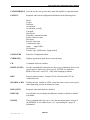
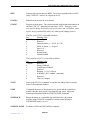
5.1.2.1 Commands for Normal Mode
AOT?
Queries the amplifier over temperature status.
ACCEL:XXXXX
Sets the commanded acceleration rate in RPM/sec. XXXXX is a number
from 1 to 65535. Note that 0 is invalid. Only valid if ramping is enabled.
ACCEL?
Returns the value of ACCEL:XXXXX command.
ATSPD?
Returns a "YES" if the motor is rotating at the correct speed as set by the
SPD:XXXXX command.
CCW
Commands counterclockwise rotation.
CLAMP
Causes the motor or spindle chuck clamp to lock down onto the work
piece or disk.
CLAMPRUN
Performs a CLAMP and a RUN command in sequence.
PAGE 21
1405260 Rev. D
MCS LA2000 GEN 2 AMPLIFIER USER'S MANUAL
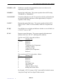
CLEARZEROPOS Exits the encoder set-up state and returns the amplifier to operation mode.
CONFIG?
Responds with system configuration information in the following form:
Speed:
Torque:
Direction:
Acceleration:
Acceleration: (on/off)
Topspeed:
Stop Speed:
Frequency: (internal/external)
System Control: remote
Polecount:
Encoder Linecount:
Commutation Type:
Angle:
Angle Offset:
Deceleration:
Encoder Type: (Differential / Single-ended)
CONFIGURE
Enters the Configuration Mode.
CURRENTQ
Displays approximate peak motor current in Amps.
CW
Commands clockwise rotation.
DECEL:XXXXX
Sets the commanded deceleration rate after a stop command is given or the
speed request is reduced to a lower speed. XXXXX is a number in
RPM/sec between 1 and 65535. Only valid if ramping is enabled.
DIR?
Requests direction status. Returns CW for clockwise and CCW for
counterclockwise.
DISABLE or DIS
Disables the unit. Similar to STOP, except the motor coasts to zero speed,
rather than being actively decelerated to a stop.
DISFAULTS?
Responds with which faults are disabled.
DISFLTQ?
Lists all faults in a text display and indicates whether each fault is enabled
or disabled.
DUMPX
These commands allow the user to view the internal parameter settings of
the EEPROM. X is a number from 1 to 5, representing the 5 pages of
information.
PAGE 22
1405260 Rev. D
MCS LA2000 GEN 2 AMPLIFIER USER'S MANUAL
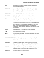
ENABLE or EN
Enables the controller and commands the motor to accelerate to the
requested speed. Same as RUN.
ENABLE?
Requests the enable status. The system responds with an ASCII string:
"ENABLED" or "DISABLED."
FAN:ON/OFF
Turns the cooling fan on or off. For protection, the drive will turn the fan
on when the heatsink temperature reaches approximately 50 degrees C,
regardless of this setting.
FAULT?
Requests the system fault status. The system responds with the ASCII
string "FAULT" if there is a fault condition, otherwise it responds with
"OK."
FLTQ?
Lists all faults in a text display and indicates whether or not each fault is in
a “FAULT” state or “OK”.
FLTA?
Requests system fault status. The system responds with hexadecimal
numbers in the form “XX YY”, indicating fault conditions.
The first word ("XX") is decoded as follows:
Bit
Meaning if Set
7 (MSB)
Reserved
6
Reserved
5
Reserved
4
Transformer Over-Temperature
3
Auxiliary #1 Fault
2
Logic Power Fault
1
Amplifier Over-Temperature
0
Reserved
The second word ("YY") is decoded as follows:
Bit
Meaning if Set
7 (MSB)
Reserved
6
Reserved
5
Reserved
4
Reserved
3
Over Speed Fault
2
Main Air Fault
1
Clamp Air Pressure Fault
0
Bearing Air Pressure Fault
For Example: If FLTA? returns “02 08”, that would be decoded to mean
“Amp Over-Temp” and “Over Speed” faults occurred.
PAGE 23
1405260 Rev. D
MCS LA2000 GEN 2 AMPLIFIER USER'S MANUAL
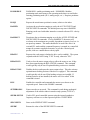
FLT?
Same as the FLTA? command, except that raw binary data is returned
instead of hexadecimal numbers.
FLTQREAD?
Returns the first value of a queue of stored values from previous faults.
The returned values are interpreted just as those returned by the FLT?
Command. This command allows for a review of faults, which occur and
clear before a standard FLT? command can be issued.
FLTQREADQ
Same as FLTQREAD? Except the result is typed out in plain text.
HEATSINKT
Displays the amplifier heat sink temperature, in degrees Celsius
(Centigrade).
ID?
Requests the controller to send back its identification information as an
ASCII string. The system responds with something similar to:
LA-2000;Model: G2;Serial: 6600000;Version: 3.00 ;Configuration: B0000
“Serial:” indicates the drive serial number (also found on the drive serial
label), “Version:” displays the installed software version number and
“Configuration:” shows the amplifier configuration code (also found on the
drive serial label).
IPLIST
Displays the network IP address and other network information.
LPR?
Queries the logic power fault status.
MENU
Provides a list of valid commands. Note: Some commands are valid only in
configuration mode.
MOTORPERIODERROR?
Used only in clocks per rev mode with the auxiliary PLL
option. Responds with the number of counts of error for one motor
revolution.
POS:XXXXX
Used on drives with the positioner option to go to a specified position,
specified in counts. Entering POS:CAP will go to the position that was
captured with the hardware position capture. SC2, Pin 10 is, by default,
configured to capture an actual position when pulled to logic level low.
POSCAP?
Responds with the hardware captured position. SC2, Pin 10 is, by default,
configured to capture an actual position when pulled to logic level low.
POSGAINS?
Lists all gain settings for the positioner option.
PAGE 24
1405260 Rev. D
MCS LA2000 GEN 2 AMPLIFIER USER'S MANUAL
POSMODE:X
POSMODE:1 enables positioning mode. POSMODE:0 disables
positioning mode and returns to the operating mode that was used before
entering positioning mode (FLL, analog torque, etc.). Requires positioner
option.
POSQ?
Reports the actual motor position in counts, relative to the index.
RAMPIN
Activates the acceleration ramping as set by the ACCEL:XXXXX and
DECEL:XXXXX commands. The default power-up state is RAMPIN.
Ramping can be used with either internal or external reference FLL velocity
control.
RAMPOUT
Deactivates the acceleration ramping as set by the ACCEL:XXXXX and
DECEL:XXXXX commands. If set to RAMPOUT, the motor will
accelerate at the maximum rate possible, dependent on inertia, load, etc. in
an open loop manner. This mode should also be used if the drive is in
external FLL mode and the command frequency is ramped in a controlled
manner by customer supplied electronics, to provide a desired speed
profile, such as a constant linear velocity spiral.
READY?
Requests the ready status (whether the drive can be enabled). The system
responds with the ASCII string "YES" if ready, otherwise "NO."
RELAYRUN
Used to close the motor output relays to allow the motor to run, if they
have been opened using the RELAYSTOP command. This command
would typically only be used if optional braking resistors are installed.
RELAYSTOP
Disables the drive and opens the motor output relays. This also activates
optional motor braking resistors if the drive is equipped. This command
would typically only be used if the braking resistors are installed. If
braking resistors are not installed, the motor will “free-wheel” if this
command is issued.
RUN
Enables the controller and commands the motor to accelerate to the
requested speed. Same as the ENABLE command.
SETZEROPOS
Enters encoder set-up mode. This command is used during mechanical
adjustment of the encoder index in encoder-only systems (TYPE:07).
SPEED:XXXXX
Used in FLL speed controlled systems using the internal synthesizer
frequency reference to set the requested speed to XXXXX RPM.
SPD:XXXXX
Same as the SPEED:XXXXX command.
SPEED?
Returns the value of the SPEED:XXXXX command.
PAGE 25
1405260 Rev. D
MCS LA2000 GEN 2 AMPLIFIER USER'S MANUAL
SPD?
Requests the current speed, in RPM. The system responds with an ASCII
string "XXXXX", where X is a digit from 0 to 9.
STATQ?
Requests system status in a text format.
STATA?
Requests system status. The system responds with hexadecimal numbers in
the form “XX YY”, indicating current status. NOTE: ‘Ramping’ status
only applies during deceleration and acceleration, and ‘In Window’ status
applies during external FLL mode, only when speed ramping is active.
The first word ("XX") is decoded as follows
Bit
Meaning if Set
7 (MSB)
System Fault
6
Reserved
5
Direction Status, 1 = CCW, 0 = CW
4
Motor at Speed, 1 = at speed
3
Speed = 0
2
Reserved
1
System Ready
0
System Enabled
The second word ("YY") is decoded as follows
Bit
Meaning if Set
7 (MSB)
Reserved
6
Energy Foldback
5
Temperature Foldback
4
Reserved
3
Ramping, 1= Up, 0=Down
2
In Window (See ‘winlimit’ command)
1
Reserved
0
Chuck is Clamped
STAT?
Same as the STATA? command, except that raw binary data is returned
instead of hexadecimal numbers.
STOP
Commands the motor to decelerate to zero speed and the controller to
disable when the motor speed is less than the stop speed. Adjust the
disable speed threshold with the STOPS:XXXXX command.
STOPLOCK
Brings the motor to a controlled stop and then locks it in position.
Requires using UNLOCK command to resume normal operation.
LOCKMODE must be set to ‘1’.
STOPUNCLAMP
Performs a STOP and UNCLAMP in sequence.
PAGE 26
1405260 Rev. D
MCS LA2000 GEN 2 AMPLIFIER USER'S MANUAL
TORQUE:XXX
Sets the torque limit to XXX percent of full scale. XXX is a number from
1 to 100. The torque limit circuit can optionally be configured by MCS to
function as a torque scaling circuit. This is desirable for analog torque
control systems as it can provide a means of programming the current
scaling. Consult MCS for more information.
TORQ:XXX
Same as the TORQUE:XXX command.
TORQUE?
Returns the value of the TORQUE:XXX command.
UNCLAMP
Causes the motor or spindle chuck to open or unclamp the disk or work
piece. Sending this command while the motor or spindle is rotating results
in an error.
UNLOCK
Releases the lock on the motor caused by issuing the STOPLOCK
command. The motor will now be in a disabled state (Internal Enable
systems) or resume external control (Torque or External Enable systems).
UNLOCK or UNLOCKRUN must be used to clear a STOPLOCK before
normal operation may resume!
UNLOCKRUN
Same as UNLOCK, except also executes a run after unlocking.
ZERO?
Requests the zero speed status. The system responds with the ASCII
string "YES" if the system speed is zero and "NO" if the motor is still
turning.
PAGE 27
1405260 Rev. D
MCS LA2000 GEN 2 AMPLIFIER USER'S MANUAL
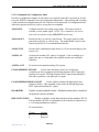
5.1.2.2 Commands for Configuration Mode
In order for configuration changes to take effect every time the controller is powered up, be sure
to use the WRITE command to save the configuration information. After entering and executing
a valid command in configuration mode, the controller will respond with ‘In Configuration State’.
After this response, the drive is ready to accept the next command.
ANALOGIN
Configures the drive for analog torque mode. The torque request is
external, as is the enable signal. NOTE: This command is not used in
units with the optional analog VELOCITY control loop.
ANALOGOUT
Returns the drive to velocity control mode. The torque request is then
generated by the FLL or velocity loop. The enable/disable control is also
returned to the RS-232 or communication interface.
ANGLE:XXX
Sets the motor commutation angle from 0 to 359 in electrical degrees (See
section 4.4).
AUXPLL:IN
Activates the auxiliary PLL option, if equipped. Used to multiply up a
single pulse per rev command to the required encoder rate command
frequency.
AUXPLL:OUT
De-activates the optional auxiliary PLL option.
CLOCKSPERREV:XXXXXX
Used to enter the master clock rate, in clocks per
revolution, on drives equipped with the high frequency PECL input and
auxiliary PLL option. The high frequency PECL input is then divided by
this value to generate a one pulse per rev signal.
CLOCKSPERREVMODE:ON/OFF
Used to enable or disable the high speed clock
frequency divider. This command is only used with the high frequency
PECL input and auxiliary PLL option.
DISABLEHH
Disables optional handheld terminal. Handheld terminal must be disabled if
the positioner option is installed.
DISFAULTS:WXYZ
Enables or disables certain faults based on the hex numbers WXYZ.
The hex numbers WXYZ are transmitted to the controller as characters (09, A-F) using standard hex notation.
W corresponds to:
Weight
8
4
Meaning
Reserved
Reserved
PAGE 28
1405260 Rev. D
MCS LA2000 GEN 2 AMPLIFIER USER'S MANUAL
2
1
Reserved
Reserved
X corresponds to:
Weight
8
4
2
1
Meaning
Auxiliary Fault
Reserved
Reserved
Reserved
Y corresponds to:
Weight
8
4
2
1
Meaning
Reserved
Reserved
Reserved
Reserved
Z corresponds to:
Weight
8
4
2
1
Meaning
Over Speed
Main air Fault
Clamp Air Pressure Fault
Bearing Air Pressure Fault
To disable a fault, add up the weights of the faults you want to disable for
each of the four hexadecimal characters. Check System Configuration
(Section 10) for the faults that were installed when unit was shipped.
DNSADDR:xxx.yyy.zzz.xyz
Enters the Domain Name Server IP address for the Ethernet
network in dotted decimal format.
ENABLEHH
Enables the optional handheld terminal. The handheld terminal must be
disabled if the positioner option is installed.
ENCODERCOUNT:XXXXX
Sets the encoder line count.
ENCODERTYPE:X Selects whether the encoder is single-ended or differential. If X is an S
then the drive is in single-ended mode, and if X is a D the drive will be
configured for differential inputs.
EXTEN
External enable mode. Causes the drive to be enabled using the external
enable signal on SC2, pin 6. A TTL low will enable the amplifier. If FLL
PAGE 29
1405260 Rev. D
MCS LA2000 GEN 2 AMPLIFIER USER'S MANUAL
speed control is used, the amplifier will also use the external direction input
on SC2, pin 13 to determine what direction to run. A TTL low on the
direction input selects CW rotation, a TTL high, or floating, selects CCW.
EXIT
Exits from the Configuration mode back to the Normal mode.
FEEDDIV:X
Used to add a divisor to the FLL velocity control loop feedback when in
external FLL mode. This is used if the maximum frequency available to the
LA2000 is limited. Setting FEEDDIV to anything other than 1 allows a
higher speed for a given input frequency, but reduces performance,
particularly low speed jitter. Choices are 1, 2, 4, and 8, with a default of 1.
FLLEXTERNAL
Sets the FLL request frequency input to the optional BNC jack or BDC
compatibility connector. The relationship of input frequency to motor
speed is given in Section 7.1.1 (FLL Velocity Loop Control).
FLLGAIN:X
Used to adjust the proportional gain of the digital portion of the FLL loop.
Valid range is -3 to 3, expressed in powers of two to result in gain settings
from 1/8 to 8. The default and recommended setting is 0 for unity digital
gain.
FLLINTERNAL
Sets the FLL request frequency input to the internal synthesizer.
GWADDR:xxx.yyy.zzz.xyz Enters the network gateway address in dotted decimal format.
INTEN
Internal enable mode. Causes the system to accept enable and direction
commands over the RS232 or communication interface as opposed to the
external TTL interface.
IPADDR:xxx.yyy.zzz.xyz
Sets the IP address of the drive, in dotted decimal format.
JERK:xxxx
Enters the Jerk setting for s-curve positioning with the positioner option.
Units are RPM / second squared.
LOCKMODE
LOCKMODE1 enables stop and lock operation (see STOPLOCK
command). LOCKMODE0 disables stop and lock operation which is
required for other options, such as angle offset.
MINSPDIN
Configures the drive for a special mode that is applicable only when the
drive is in external frequency input mode. The command allows the user to
use the stop speed to set up a minimum speed at which the drive will
enable. If the external frequency is above the stop speed, the drive will
enable and operate normally; frequencies below this speed will stop the
drive.
PAGE 30
1405260 Rev. D
MCS LA2000 GEN 2 AMPLIFIER USER'S MANUAL
MINSPDOUT
Configures the drive for normal operation with external frequency.
OFFSET:XX
Sets a direction dependent amount of angle offset from 0 to 99 degrees to
be added or subtracted to the base motor commutation angle as input with
the ANGLE:XXX command. OFFSET is added to ANGLE for CW motor
rotation and subtracted from ANGLE for CCW motor rotation (See
section 4.2.2). Requires disabling of Stop and Lock operation
(LOCKMODE0).
OVERSPEED:XXXXX
POLES:XX
Sets the speed in RPM at which an over speed fault will occur.
Sets the motor pole count.
POSACCEL:XXXXX
Sets the acceleration rate (in RPM / second) for positioning mode,
if equipped with the positioner option.
POSDECEL:XXXXX
Sets the deceleration rate (in RPM / second) for positioning mode,
if equipped with the positioner option.
POSDGAIN:XXXX
Enters the derivative gain for the positioner option.
POSDSAMPLE:XXXX
Enters the derivative sample time for the positioner option.
POSIGAIN:XXXX
Enters the integral gain for the positioner option.
POSILGAIN:XXXX
Enters the integration limit for the positioner option.
POSMAXVEL:XXXXX
Enters the maximum velocity for positioning mode, if equipped
with the positioner option.
POSPGAIN:XXXX Enters the proportional gain for the positioner option.
READ
Retrieves old configuration data and wipes out any new configuration data.
SAVE
Writes the new values of the configuration to the EEPROM. Use this
before exiting the Configuration mode. The unit must be powered down
and powered back up again for the new configuration to be valid. Same as
the WRITE command. All changes made to any operating or setup
parameters must be saved before turning off power or else they will revert
to their last saved settings.
STARTS:XXXXX
Sets the speed at which the motor controller enables when in minimum
speed detection mode (MINSPDIN).
PAGE 31
1405260 Rev. D
MCS LA2000 GEN 2 AMPLIFIER USER'S MANUAL
STOPS:XXXXX
Sets the speed at which the motor controller disables after a receiving a
STOP command. XXXXX is the motor speed in RPM. The default value is
30 RPM.
SUBMASK:xxx.yyy.zzz.xyz Enters the subnet mask for the Ethernet network in dotted decimal
format.
TOPSPEED:XXXXX
Selects type of commutation. If you are using a motor with an encoder and
Hall Effect devices, this number is 06. If you are using a motor with only
an encoder, the commutation type is 07.
TYPE:XX
!
Sets the top selectable speed for the motor.
CAUTION: It is important that this number is correct. The amplifier employs a
different commutation scheme for a motor with Hall Effect devices.
ATTENTION : il est important que ce nombre soit correct. L’amplificateur utilise un
schéma de commutation différent pour les dispositifs à effet Hall.
WINLIMIT:XX
Sets the window for speed ramping in external FLL mode. Entered in
tenths of a percent. I.E., if WINLIMIT is set to 30, a change in the
reference frequency of 3% or more will cause the drive to perform a
controlled ramp to the new velocity, and a step of less than 3% will cause a
step response in the velocity. WINLIMIT has no effect in internal FLL
mode or if ramping is turned off.
WRITE
Same as SAVE.
PAGE 32
1405260 Rev. D
MCS LA2000 GEN 2 AMPLIFIER USER'S MANUAL
5.2
Hardware Interface
NOTE: For operation of communications controlled systems, see section 6.2.1.
5.2.1 TTL Interface
The LA2000 Gen. 2 has the ability to accept external direction, enable, and frequency request
signals. This allows for a very simple user interface to the drive. In order to configure the drive
for using the external enable and direction signals, use the EXTEN command in the configuration
mode. If the drive is also configured for external frequency operation (FLLEXTERNAL) then
the speed will correspond to the external frequency input (see Section 7.1.1 FLL Velocity Control
Loop). If the internal frequency synthesizer is selected (FLLINTERNAL) the motor controller
will go to whatever speed is the power-up default. To enable the drive pull SC2, pin 6 to logic
common. An open or logic 1 (+5V) on SC2, pin 6 will disable the drive. A logic 1 (+5V), or
open, on SC2, pin 13 corresponds to CCW rotation, while a 0, or logic common, will cause CW
rotation. On drives using the STOPLOCK command and external enable input, the enable line
must be grounded during the entire time the motor is in the locked condition, or else the
controller will disable. This is to provide an emergency way to disable the amplifier without a
software command. If the drive does become disabled, issue the UNLOCK command prior to reenabling, otherwise undesired operation may occur.
5.2.2 Analog Interface (Analog Torque mode control)
The analog interface option allows the drive to be interfaced through a +/- 10V single-ended
analog signal. Control loops must be closed external to the drive. The input command voltage
corresponds to the amplitude level of the current in the motor. The default scaling is 1V = 1.5A
peak. If the drive is equipped with the optional SCALE potentiometer, the scaling can be
adjusted to produce a lower current for a given command voltage. If the drive has been
optionally configured such that the Torque Limit circuitry provides a current scaling rather than a
limit, the TORQUE command can be used to remotely reprogram the drive’s current scaling.
Positive signals cause CCW rotation, and negative signals cause CW rotation. ANALOGIN is
the command which puts the drive into this mode. The drive is enabled through SC2, pin 6, as
above, and the torque command is input at SC, pin 5.
5.2.3 Analog Interface (Analog Velocity mode control)
An analog velocity loop option is available to enable speed control through a +/- 10V singleended analog signal. This option must be installed at MCS. The amplifier must be configured
using the ANALOGOUT and EXTEN commands when velocity control is desired (as opposed
to torque mode control). The drive is enabled through SC2, pin 6, as above, and the velocity
command is input at SC2, pin 5. Contact MCS for more information on this option if required.
PAGE 33
1405260 Rev. D
MCS LA2000 GEN 2 AMPLIFIER USER'S MANUAL
5.3
Error Messages And Their Meanings
When entering commands, the system may not be able to process the command for various
reasons. The table below describes the error codes and the probable cause of the error.
Error code
0?
2?
3?
6?
Error message
Unrecognized command
Invalid request
Unable to change setup
Command string too long
Possible Cause
____________
Spelling of command incorrect
Input data out of acceptable range
Drive needs to be disabled
PAGE 34
1405260 Rev. D
MCS LA2000 GEN 2 AMPLIFIER USER'S MANUAL
Part 6
OPERATION
6.1
Power Up
F
!
WARNING: Before powering up for the first time, ensure that the system has
been installed and wired correctly. Refer to Part 3: Installation.
AVERTISSEMENT : Avant la première mise sous tension, s’assurer que le
système a été installé et câblé correctement. Consulter la partie 3 : Installation.
CAUTION: Improper installation may cause damage to the unit.
ATTENTION : Une installation incorrecte peut endommager l’unité.
Applying power sets the internal scale factors and auxiliary outputs to the power-up
configuration. The drive is not ready for operation until approximately 2-3 seconds have elapsed.
The configuration is dependent on the default settings for your system. You are able to change
the default Speed, Acceleration, Torque, Direction, and other parameter values by using the
WRITE command in configuration mode. See Section 5.1.2 Command Summary.
In encoder-only equipped systems, when the unit is enabled after power-up, it goes into an
encoder initialization state. In this state, the motor is locked in a known position to initialize the
position counter. This state lasts a few seconds, after which the commutation logic automatically
goes into its normal operating mode.
!
CAUTION: After the lockup state the motor could turn in the wrong direction
momentarily. If this is not allowable in the system, MCS suggests using Hall Effect
devices along with the encoder to ensure proper startup.
ATTENTION : Après un blocage, le moteur peut temporairement tourner dans le
mauvais sens. Si le système ne le permet pas, MCS recommande l'utilisation de
dispositifs à effet Hall avec le codeur afin de garantir un démarrage correct.
This does not apply to systems using Hall Effects, since absolute position is always known.
PAGE 35
1405260 Rev. D
MCS LA2000 GEN 2 AMPLIFIER USER'S MANUAL
6.2 Normal Operation
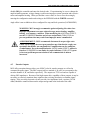
6.2.1 Communications Controlled Systems
After the amplifier has powered up, and the communications interface has transmitted
“Configuration Complete” (approximately 2-3 seconds), it is ready to accept commands. Refer to
Section 5.1.2 Command Summary. Input a speed (SPEED:XXXXX) and direction (CW or
CCW) command, followed by a RUN command in order to start motor rotation.
Under normal operation, the amplifier can be in either an Enabled, a Stop, or a Disabled state.
When Enabled, the system is in servo and the amplifier is controlling motor currents in such a way
as to hold the motor at or accelerate it to its set speed.
When a STOP command is issued, the motor is commanded to decelerate to the stop speed (see
STOPS:XXXXX command description) and then disable. If the motor kicks back in the wrong
direction at the end of a stop, increase the stop speed. If the motor spins down too long, decrease
the stop speed.
When in the Disabled state, the amplifier is effectively commanding zero motor current, allowing
the motor to spin freely. In this state, the amplifier does not transfer power to or from the motor.
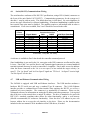
6.2.2 Interlocks and Faults
Interlock circuits continually monitor certain conditions external and internal to the unit. The
interlocks disable the amplifier if these conditions stray outside of specified limits. In addition to
the standard interlocks, the user can configure auxiliary inputs to monitor specific external
conditions. Those conditions that cause the interlocks to disable the amplifier are called FAULT
conditions. After receiving a fault condition, the LA2000 will disable or stop and enter a FAULT
state.
The FAULT state is latching: the unit will stay in this state, even after the removal of the faultcausing condition. While in the FAULT state, the LA2000 will not accept a RUN or ENABLE
command until a STOP or DISABLE command is issued. If, after a STOP or DISABLE
command, the amplifier is still in FAULT mode, the fault is still present in the system.
There are two types of interlocks, internal and external. Internal interlocks are those protecting
the motor controller. External interlocks are those related to the user's equipment and are
connected to the drive through the SC2 connector. All interrupts are active high, which means
that for a no-fault condition there must be 0V (logic common) at the input of the controller.
Unused interlocks can be disabled by connecting them to common or using the
"DISFAULTS:WXYZ" command (see Section 5.1.2.2 Commands for the Configuration Mode).
The following table shows the pin outs of the interlocks and their functions.
PAGE 36
1405260 Rev. D
MCS LA2000 GEN 2 AMPLIFIER USER'S MANUAL
Interlock
Auxiliary Interlock
Main Air Sense
Bearing Air Sense
Clamp Air Sense
Amp Overtemp
Logic Power Fault
Transformer Overtemp
Pin
SC2-7
SC2-14
SC2-18
SC2-19
Internal
Internal
Internal
Function
Disables the controller
Stops the controller
Stops the controller
Disables the controller
Disables the controller
Disables the controller
Disables the controller
NOTE: Logic Common is available on SC2, pins 9 and 25. Analog Ground is available on
SC2, pin 8.
Auxiliary Interlock: The normal use for this interlock is to run wires from pin 7 and logic
common (or analog ground) out along any cable connected to SC2 and connect the wires after the
last connector. This will cause the system to fault if the cable becomes disconnected or severed.
This interlock is also compatible with a PTC motor thermistor, or a normally closed thermal
switch, if the motor is equipped with this type of over temperature detector.
Main Air Sense, Bearing Air Sense, and Clamp Air Sense: These are all customer
configurable interlocks. If not used, they may be tied to logic common or disabled through the
"DISFAULTS:WXYZ" command. Note: The Clamp Air Sense input will not create a fault
while the amplifier is disabled, so that the chuck can be unclamped without creating a fault
condition. The Clamp Air Sense input must be driven low prior to enabling the amplifier,
otherwise a fault condition will result.
The amplifier internal faults are as follows:
Amp Overtemp - This is an internal fault, which will disable the controller if the temperature on
the heatsink reaches 80°C. If this fault occurs, verify that the fan inlet or outlet is not obstructed
and that the ambient temperature does not exceed 40°C.
Logic Power Fault - This fault occurs if the internal logic voltages exceed their limits.
Transformer Overtemp - This fault disables the amplifier if the transformer reaches
approximately 120 °C.
Overspeed – This fault occurs when the motor speed exceeds the overspeed threshold (see
OVERSPEED:XXXXX command).
PAGE 37
1405260 Rev. D
MCS LA2000 GEN 2 AMPLIFIER USER'S MANUAL
Part 7
THEORY OF OPERATION
The amplifier can be thought of as consisting of two sections: control and power. The power
section channels energy from the power input to the motor; the control section directs the power.
These sections are further explained below.
7.1 Control Section
See Drawing #1405190, Control Level Schematic for more information.
7.1.1 FLL Velocity Control Loop
The Frequency Lock Velocity Control provides extremely accurate speed control using a
combination of frequency and phase lock methods. Frequency and phase comparisons between a
reference pulse-train and a feedback pulse-train result in internal command voltages that control
the motor speed. The Frequency Lock Velocity Control generates a torque command voltage that
is proportional to the difference between the two frequencies, causing the motor to accelerate or
decelerate until the two frequencies are equal.
In most systems that use the Frequency Lock Velocity Control, incremental encoders are used to
generate the feedback pulse-train. The reference pulse-train is generated by either an internal
frequency synthesizer or an external TTL pulse-train. The external reference is input through an
optional BNC connector or the optional BDC compatibility connector located on the front of the
controller. The selection of the internal synthesizer or external input is made by the
FLLINTERNAL and FLLEXTERNAL commands. Note: Systems equipped with and using
the Auxiliary PLL option should be set to FLLINTERNAL even though the command signal is an
external pulse train.
When using the external FLL mode, the FEEDDIV command allows some flexibility if the
maximum frequency available from the external circuitry is limited. Using a value other than the
default (1) divides down the feedback pulse train (by 2, 4, or 8 with a setting of 2, 4, or 8,
respectively). This lowers the required command frequency for a given motor speed, but
decreases performance, particularly low speed jitter. The FEEDDIV setting can be viewed with
the DUMP4 command.
When using an external reference frequency, the formula for the frequency is f = (speed request in
RPM * encoder line count) / (FEEDDIV * 60 Hz). Example: The external reference frequency
for a system with FEEDDIV = 1, using a 1024 line encoder and rotating at 3600 RPM is 61.440
kHz.
In systems configured for Analog Torque control, the FLL Velocity Control is bypassed to allow
an external controller to close the loop.
PAGE 38
1405260 Rev. D
MCS LA2000 GEN 2 AMPLIFIER USER'S MANUAL
7.1.2 Commutation Section
The LA2000 is a three phase drive for sinusoidally wound DC brushless motors. This means that
the voltage generated across each phase by turning the rotor at a constant speed has a sinusoidal
waveform. The magnitude of the generated voltage is proportional to the angular velocity of the
rotor. Phase V and phase U voltages lag phase W voltage by 120 and 240 electrical degrees,
respectively. In order to develop constant torque from the motor, sinusoidal currents must be
injected into each motor winding in phase with the generated voltages. For this, the angular
position of the rotor must be known at all times. The LA2000 determines the rotor position by
converting the output signals of an encoder to a digital word that represents the absolute rotor
position. This word is then converted to three phase words that are each multiplied with a velocity
error (or torque command) signal to generate the three sinusoidal current request signals.
NOTE: Units equipped with the MCS-installed Sine/Sine+120 option use customersupplied external commutation for the W and V phases. The third phase is generated
internally.
7.1.3 Motor Phase Current Control Loop Section
The current control loops compare the three phase current requests from the velocity loop and
commutation section with the actual motor phase currents and generate three current error signals
that request output voltage from the power stage.
7.2 Power Section
The power section consists of the Main Power Supply and the Power Amplifier Stage.
The Main Power Supply is a transformer-isolated, full-wave rectified, unregulated, bipolar DC
power supply. It provides a source of power for the three motor output phases.
Each motor phase also has its own amplifier stage. These electrically quiet, linear power stages
consist of level-shifting circuitry and power semiconductor devices, which amplify the current
error signals. The voltage that is applied to the motor terminals induces currents, which generate
torque and motor rotation.
PAGE 39
1405260 Rev. D
MCS LA2000 GEN 2 AMPLIFIER USER'S MANUAL
Part 8
SERVICING
Servicing procedures are not recommended. Do not attempt to service without consulting with
MCS first.
F
8.1
WARNING: Dangerous voltages exist at several places within the enclosure.
Disconnect power before and during any disassembly or servicing. Only
qualified personnel should service this product.
ATTENTION : Des tensions dangereuses existent à différents emplacements du
site. Couper l’alimentation avant et pendant toute manipulation ou toute
opération d’entretien. Seul du personnel qualifié peut assurer l’entretien de ce
produit.
Maintenance
LA2000 motor controllers do not require regular maintenance. However, cooling fans and
heatsink fins should be inspected for dust accumulation, which interferes with the air-cooling
system. Dust can be removed from the LA using a clean pressurized (less than 40psi) air stream.
The inspection schedule will depend on the amount of dust in the location of the motor controller.
8.2
Troubleshooting
The purpose of this section is to provide a guide for identifying problems related to installation,
adjustment, or application of the LA2000 motor controller. The guide is not intended as a service
manual for the repair of damaged components. Service procedures should not be attempted
without first consulting with MCS.
*Nothing happens when the power switch is turned on
Problem
No power to the LA2000
Solution
Be sure that one end of the power cord is plugged into the rear panel receptacle
and that the other end is plugged into an appropriate active outlet.
Problem
Fuse is blown
Solution
Disconnect the power to the LA2000 and remove the fuse from the power entry
module. Test the fuse for continuity and replace it if there is none. Check external wiring,
specifically the motor phase outputs. When the controller blows fuses it usually means that
something is shorted out, or the Power Entry Module voltage setting is incorrect. The
replacement must have the same current and voltage rating as the fuse that was removed.
PAGE 40
1405260 Rev. D
MCS LA2000 GEN 2 AMPLIFIER USER'S MANUAL
No serial (RS232) communications
Problem
Incorrect communications parameters
Solution
Verify that the communication parameter settings on the host PC are: a) 8 data
bits, b) 1 stop bit, and c) no parity. Also confirm that the baud rate setting on the host matches
that of the LA2000. The LA2000 does not use handshaking.
Problem
Receive and transmit lines reversed on the communications cable
Solution
Reverse the signals at pins 2 and 3 on the LA2000 side of the cable.
Logic Power Fault
Problem
The internal logic power supplies are outside of specification
Solution
Check all external wiring and make sure that there are no excessive loads on any
of the logic power outputs.
Amp Overtemp Fault
Problem
The amplifier heat sink has exceeded a high temperature threshold
Solution
If the amplifier has recently faulted, determine whether the air exiting from the
rear of the LA2000 is hot or whether it has an unusual smell. At the same time, verify that the
cooling fan is working and unobstructed. Disable the LA2000 and allow the amplifier to cool.
Verify that the motor commutation was adjusted correctly (see Section 4.4), and that the motor
turns smoothly when the LA2000 is enabled
The LA2000 enables but the motor does not turn
Problem
Commanded speed is zero
Solution
See section 5.1.2 and make sure that you have entered a non-zero speed request.
The default speed request is zero.
PAGE 41
1405260 Rev. D
MCS LA2000 GEN 2 AMPLIFIER USER'S MANUAL
Problem
The LA2000 is still in the encoder setup state
Solution
The LA2000 is in a setup state for a few seconds after it has been enabled for
the first time after power-up. During the setup state the motor locks into a position and does
not rotate. The setup state can also be entered indefinitely by entering the SETZEROPOS
command. If in the encoder setup mode, enter the command CLEARZEROPOS to return to
normal operation.
Problem
The motor feedback device (encoder) is not wired to SC2 correctly
Solution
See Section 4.3 and verify connections to SC2.
Problem
The commutation is not adjusted properly
Solution
Verify correct commutation adjustment (see Section 4.4).
Problem
The motor leads are not wired properly
Solution
See Section 4.2 and verify the wiring to the motor.
LA2000 enables, but motor is locked up (shaft will not rotate, even by hand)
Problem
The encoder line count or the pole count does not match the system
requirements.
Solution
system.
Set the encoder line count and motor pole count to the correct values for your
Problem
The phase relationship on the encoder inputs is reversed
Solution
Check to see if the phase relationship between the encoder outputs is correct.
The correct inputs to the amplifier are A leading B when the motor is turning in a clockwise
direction.
Problem
All three Hall Effect devices are not present
Solution
Check system wiring to be sure that all Hall Effect devices are present and
switching. (Refer to section 4.3.3)
PAGE 42
1405260 Rev. D
MCS LA2000 GEN 2 AMPLIFIER USER'S MANUAL
Part 9
SPECIFICATIONS
9.1
General
Fuse/Fusible:
115V: 10A, 250V
230V: 6A, 250V
Power Requirements: 120VAC, 10A or 240VAC, 6A (10%)
Power Output:
15A peak sinewave (intermittent), 8A peak sinewave (continuous), 75V
nominal bus voltage at continuous current rating.
Dimensions:
Width: 7.25”
Height: 6.25”
Depth: 11” (not including optional mounting flange)
Weight: 22 lbs. nominal
Environmental:
Temperature: 0°C to 40°C Ambient Air Temperature
Humidity: 5 to 80%, Non-Condensing
9.2
Connector Definitions
The connector pin definitions follow. Refer to the sections listed for further information about
each connector and signal definitions.
9.2.1 SC-5: RS232 Serial Connector
[From Section 4.6]
Amp DE9
Female
Connector
Signal Name
1
Ground
2
Receive
3
Transmit
4
Handheld Term. RX
5
Ground
6
At Zero Speed
7
Handheld Term. TX
8
At Speed
9
+5V
Connect To Terminal
Standard Serial Port
DE9
DB25
1
3
2
2
3
5
7
-
PAGE 43
1405260 Rev. D
Serial Port Function
Shield
Transmit
Receive
N/A
Ground
N/A
N/A
N/A
N/A
MCS LA2000 GEN 2 AMPLIFIER USER'S MANUAL
9.2.2 SC-2: Commutation (Motor Feedback) Connector
[From Sections 4.3.1 through 4.3.2]
PIN #
1
2
3
4
5
6
7
8
9
10
11
12
13
14
15
16
17
18
19
20
21
22
23
24
25
ENCODER and HED
+5V (Red)*
(250 mA MAX )
A Channel Input
B Channel Input
I Channel Input
External Analog (Torque or Velocity) Input
External Enable Input
Auxiliary Interlock: 0V = OK +5V = Fault
Analog Ground
Logic Common (Black)*
Configuration Specific Input **(See Note Below)
Clamp Output ***(See Note Below)
!I Channel Input
External Direction Input
Main Air Fault Input
H1 (Yellow)*
H2 (Green)*
H3 (White)*
Bearing Air Fault Input
Clamp Air Fault Input
!A Channel Input
!B Channel Input
-15V (125 mA MAX)
+15V (125 mA MAX)
Chassis Ground
Logic Common
*(MCS Motor Wire Colors are given in parentheses)
** Default use is POSITION CAPTURE. May have future functionality for other application-specific functions.
*** 0 V = clamp
*** +15 V = unclamp
9.2.3 Motor Power Connector
Mating Connector: Tyco/AMP P/N: 206044-1
Mating Pins: Tyco/AMP P/N: 66361-2 (14-18 AWG wire) or 66103-2 (20-24 AWG wire)
[From Section 4.2.1]
Pin #
1
6
8
14
3-LEAD MOTOR
Phase Name
Phase W
Phase V
Phase U
GROUND
PAGE 44
1405260 Rev. D
MCS LA2000 GEN 2 AMPLIFIER USER'S MANUAL
Part 10
LIST OF DRAWINGS
The drawings that are referenced in this section are located in the “pdfs” directory on this
CDROM manual.
Outline and Mounting Drawing:
1405210
LA2000 Gen. 2 Outline, Mounting dimensions and Connector Locations
System Wiring Diagrams:
1405150
Connection Diagram for RS-232 Controlled Encoder Commutated Systems
Printed Circuit Board Drawing:
1405180
Control Card Component Layout
Control Level Schematic
1405190
LA2000 Gen. 2 Control Level Schematic
PAGE 45
1405260 Rev. D
MCS LA2000 GEN 2 AMPLIFIER USER'S MANUAL
AVAILABLE OPTIONS (as of 1/5/10)
MCS may add additional options and features in the future. Contact MCS Sales Department for
information on pricing of the following factory installed options:
BDC Compatibility - Includes the BDC compatibility connector and configuration settings
compatible with the legacy BDC-0610 drive. An optional mounting flange is also available.
BNC I/O Connector - Includes BNC panel connectors for encoder and index outputs as well as
the command frequency input.
Positioner - Includes a powerful motion processor to add position loop control to the drive.
Control can be easily switched between positioning and other modes, such as FLL, as needed.
Analog Torque Control - Standard Feature, but specifying this option will include factory
configuration for software control of current scaling and default configuration for torque control.
Please specify whether the command is single-ended or differential.
Analog Velocity Control - Includes internal tach generation circuitry and an analog velocity loop
to accept a +/- 10 V input proportional to velocity. Balance and Scale adjustment potentiometers
are included.
Sine / Sine +120 Commutation - This option bypasses the LA2000’s internal commutation
circuitry for use with special applications or motion controllers that perform commutation. The
user will input +/- 10V analog current request signals for two motor phases. The third phase is
generated internally.
High Frequency PECL-level Command Input / AUX PLL – This option is application specific
and provides a method of locking spindle speed to a “master clock”. An additional connector is
provided to accept a high frequency PECL (differential Positive Emitter Coupled Logic) level
signal for frequency command at a programmable “master clock” rate. This signal is divided
down to a once per revolution pulse. The once per revolution pulse is multiplied up using the
auxiliary PLL to the encoder line rate for FLL velocity control. The connector also includes pins
for an auxiliary analog input for a summing junction, analog outputs for velocity error before and
after the summing junction, and a buffered TTL-level index signal output. This option is
application specific and not available for all encoder counts and speed ranges.
Sinewave (Analog) Encoder Inputs - This option includes interface circuitry to connect a 1V
pk-pk analog output encoder to the drive, instead of the standard digital encoder. This is useful if
an encoder interpolator is required elsewhere in the system for customer supplied motion control
or measurement electronics. It is also useful where EMI is a concern as analog output encoders
eliminate fast rising edges.
Braking Resistors - Consult MCS if command-actuated resistive braking or emergency stopping
in the event of a power failure is desired. The optional resistors are connected by relays between
the motor phases when the “RELAYSTOP” command is issued or if AC power is lost.
PAGE 46
1405260 Rev. D