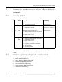
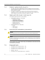
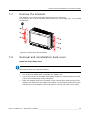
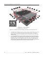
1
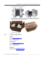
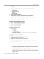
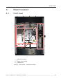
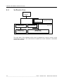
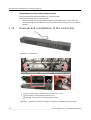
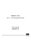
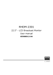
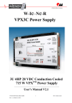
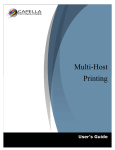
RHDM-1701
16.5" LCD Broadcast Monitor
Maintenance Manual
K5960059-00
Intentionally left blank
2 _______________________________________________ Barco - RHDM-1701 - Maintenance Manual
About the manual
1
About the manual
1.1
Contents of the maintenance manual
This manual consists of the following chapters:
Chapter 1: About the manual
Chapter 2: Important notices, product safety precautions and package
and storage
The chapter contains important notices and safety precautions providing
essential juridical and technical information about the purchased product.
Chapter 3: About the product
Chapter 4: Board location
This chapter gives an overview of the location of the electronic boards within the
unit.
Chapter 5: Hardware and software module overview
A hardware and software module overview plus a list of configuration
possibilities are shown and listed in the chapter.
Chapter 6: Diagnostics
In case the unit does not behave normal, some general tips are listed in this
chapter. By following the Fault Finding Tree, a service engineer will find, on an
easy way, the faulty unit.
Chapter 7: Removal and reinstallation of electronic boards
If a faulty board is detected by means of the previous chapter, then it can be
swapped following the procedures of this chapter.
Chapter 8: Interconnections
This chapter describes the internal connections between the different boards and
modules of the unit.
Chapter 9: Adjustment procedures
After swapping a board, it might be necessary to perform some adjustments, if
this is the case then these adjustments procedures are described here.
Chapter 10: Maintenance
This chapter contains the cleaning instructions of the LCD screen and the cover
of the unit.
It also describes the function and the general operation of the Barco keypad as
maintenance interface (if applicable).
An overview of preventive maintenance to be performed on regular bases is also
given in this chapter.
Chapter 11: List of abbreviations
1.2
Change record
Revision
Date
Description
00
Aug-10
Initial release
Barco - RHDM-1701 - Maintenance Manual _______________________________________________ 3
About the manual
1.3
Notation convention
Following notations are applicable to this manual and should be respected
throughout the manual.
WARNING:
Warnings – presented in this manual, provide information, which if not adhered to, may result
in personal injury or death.
CAUTION:
Cautions – presented in this manual, provide information, which if not adhered to, may result
in damage to the equipment.
NOTE:
Notes – presented in this manual, provide information, which emphasize points, significant to
understand and operate the unit.
IMPORTANT:
Important – presented in this manual, provide information, which is important to highlight.
4 _______________________________________________ Barco - RHDM-1701 - Maintenance Manual
Important notices, product safety precautions and package & storage
2
Important notices, product safety precautions and package & storage
2.1
Read carefully
IMPORTANT:
Please read the important notices and safety precautions, mentioned in the following paragraphs, carefully. They provide essential juridical and technical information about the purchased product.
2.2
Important notice
2.2.1
Copyright
© Barco n.v., All rights reserved.
The information contained herein is Barco confidential information. No part of
the information contained herein may be disclosed outside of the organization of
the recipient, its sub-contractors, and customers in any form or by any means
and/or stored in a database or retrieval system without the prior written consent
of Barco.
2.2.2
Technical accuracy notice
Although every attempt has been made to achieve technical accuracy in this
document, we assume no responsibility for errors that may be found. Our goal is
to provide you with the most accurate and usable documentation possible; if you
discover errors, please let us know.
2.2.3
Federal Communication Commission (FCC) notice
This equipment has been tested and found to comply with the limits of an FCC
class (refer to the technical specifications of the specific unit for more details
about the corresponding class). These limits are designed to provide reasonable
protection against harmful interference when the equipment is operated in a
commercial environment. This equipment generates, uses and can radiate radio
frequency energy and, if not installed and used in accordance with the
instruction manual, may cause harmful interference to radio communications.
Operation of this equipment in a residential area is likely to cause harmful
interference in which case the user will be required to correct the interference at
his own expense.
2.2.4
Warranty
During the warranty period, Barco n.v. will do all repairs free of charge
(material and labor). The faulty parts or units have to be shipped freight
prepaid to a Barco n.v. regional service center. Barco n.v. will pay the
freight charges when the repaired parts are shipped back to the
customer's site.
Damage of equipment due to improper use or negligence of the safety
Barco - RHDM-1701 - Maintenance Manual _______________________________________________ 5
Important notices, product safety precautions and package & storage
precautions incorporated in this manual are not covered by this
warranty.
The warranty does not include the following:
2.2.5
•
Any hardware or software item procured from a source other than Barco n.v.
or their official agent or distributor and integrated by Customer or a third
party into Barco n.v. supplied equipment.
•
Any host or system configuration not explicitly supported by Barco n.v..
•
Consumables such as projector lamps, dust filters, ...
•
All software installed on the system, whether they are acquired from Barco
n.v. or a third party. An exception is made for software delivered by Barco
n.v. that would prove to be a cause for the malfunctioning of the hardware
covered under this Agreement.
•
If any payment remains outstanding from the Purchaser to the Seller.
•
Normal wear and tear, use under circumstances exceeding specifications,
abuse, unauthorized repair or alteration, lack of proper maintenance.
•
In the particular case of LCD displays, to the case of image retention phenomena (shadows, dark lines and other image artifacts), that may result
from a usage outside of the specification.
•
Any failures resulting from an accident, negligence (such as but not limited
to removing or deleting system files & licensed software product files), misuse, circuit failure or any change, damage due to fire, water, thunder or
lightning, power failure or fluctuation, disruption of communication lines or
due to force majeure, or any reason foreign to the equipment.
•
Any specific services or procedures, asked for by the Customer, related to
verification of repaired equipment.
•
If several failures occur which are excluded from warranty due to circumstances such as fire and if Barco n.v.’s understanding that these circumstances may result in damage to other hardware under agreement, then
Barco n.v. is entitled to terminate the contract. No fees will be paid back by
Barco n.v. in this case. Inspection of equipment will be required prior to the
continuation of this Agreement; the same terms and conditions as for the
inspection prior to the contract apply.
Trademarks
Brand and product names mentioned in this manual may be trademarks,
registered trademarks or copyrights of their respective holders. All brand and
product names mentioned in this manual serve as comments or examples and
are not to be understood as advertising for the products or their manufactures.
2.2.6
Open source license
This product contains software components released under an Open Source
license. A copy of the source code is available on request by contacting your
sales representative.
See appendix A for details.
6 _______________________________________________ Barco - RHDM-1701 - Maintenance Manual
Important notices, product safety precautions and package & storage
2.3
Safety precautions
2.3.1
Service safety precautions
WARNING:
Electric shock or fire hazard can be caused if critical components are replaced by nonconforming components. These components are marked in this guide by a
with conforming types only!
2.3.2
sign. Replace
Product safety notice
WARNING:
Many electrical and mechanical parts in display units have special safety-related
characteristics. These characteristics are often not evident from visual inspection nor can the
protection afforded by them necessarily be obtained by using replacement components rated
for higher voltage, wattage, etc. Replacement parts that have these special safety
characteristics are identified in this data and its supplements and bulletins. Electrical
components having such features are identified by
or * on the schematics and on the
parts lists in this data and its supplements and bulletins. The use of a substitute replacement
that does not have the same safety characteristics as the recommended replacement part
shown in the parts lists in this data and its supplements and bulletins, may create shock or fire.
2.3.3
Earthing
WARNING:
The display unit must be earthed correctly. Verify that the power cable is plugged into a
standard 3-pin power outlet which is effectively earthed. When using extension cords, make
sure that they contain a grounded connection. If in doubt, contact a qualified electrician.
Ignoring this warning may lead to personal injury or death.
2.3.4
Electro Static Discharge (ESD) notice
CAUTION:
The unit contains ESD sensitive subassemblies. The equipment has been built in accordance
with the Barco ESD protection procedure. Use an earth strap during service interventions!
2.3.5
Electrical warnings and cautions
•
Do not power the unit with other input sources as specified in the technical
specifications.
•
Always power-down the unit before disconnecting the power cable.
•
Unplug the display unit from the power source when not in use.
Barco - RHDM-1701 - Maintenance Manual _______________________________________________ 7
Important notices, product safety precautions and package & storage
IMPORTANT:
Immediately unplug if:
•
the power supply cord is damaged.
•
the unit has been dropped or the cabinet is damaged.
•
the unit does not operate normally by following the operation instructions.
WARNING:
Do not remove the cover without authorization. Removal of the cover by non-qualified
personnel can cause personal injury.
2.3.6
2.3.7
Environmental cautions
•
Do not use the display unit in a dusty or damp room.
•
Do not submit the display unit to heavy shocks and/or vibrations.
•
Do not cover the display unit while in operation to avoid overheating.
•
Do not expose to direct sunlight.
•
Do not use the display at extreme limits of temperature and humidity range.
Storage and operating limits are specified in the technical specifications of
the unit.
Requirement for dusty environments
The room in which the display unit is installed and operational must be dustfree. The room must comply with a dust class of 8 or better according to
ISO14644-1. If the room in which the display unit is installed does not comply
with the dust class stated above, please contact Barco to discuss possibilities to
protect the display unit against dust.
NOTE:
All construction, reconstruction, decoration activities must be completed before the installation
and operation of the product.
2.3.8
LCD screen
•
Do not apply pressure on the surface of the screen. If ‘waves’ are visible on
the screen below the pressing object (e.g. finger), the pressure is already
too high and the LCD may already break under these circumstances.
•
Do not hit the LCD screen with hard objects.
•
Do not rub the LCD screen with rough materials.
•
Do not touch the LCD screen with hard materials. Hard materials can cause
scratches on the surface of the LCD screen. Examples of hard material are:
fingernails, pencils, pens and styluses, wooden, plastic or metal objects.
•
While moving the display unit manually, hold the LCD screen away from your
body to avoid scratching the LCD screen.
8 _______________________________________________ Barco - RHDM-1701 - Maintenance Manual
Important notices, product safety precautions and package & storage
2.3.9
2.3.10
•
Do not paste or stick objects with glues and/or adhesive tapes on the LCD
screen.
•
Wipe off water droplets or oil immediately. Ignoring this precaution could
lead to staining and/or discoloration of the LCD screen.
•
Do not expose the LCD screen to direct sunlight.
Cover
•
Do not place objects on the cover.
•
Do not spill fluids over the cover or the LCD screen.
•
Do not push objects into ventilation openings of the display unit.
Hazardous materials
WARNING:
The LCD panel is composed of multiple layers of glass and protective glass with a small amount
of liquid in between. Rough handling or dropping can cause the LCD panel to break. If any part
of the skin or body comes in direct contact with the liquid, immediately wash the affected areas
with plenty of water for at least 15 minutes. If any symptoms are present after washing, get
medical care.
2.4
Package and storage
2.4.1
General
A safe transport of the units can only be guaranteed if the original undamaged
package is used for shipping. Handle with care when transporting.
Keep your original packaging. It is designed for this unit and is the ideal
protection during transportation.
2.4.2
Procedure in case of damages
All shipments should be opened and inspected for concealed damage or pilferage
as soon as possible after the arrival at destination. The shipping cartons should
be retained for the surveyor’s inspection and full and accurate reserves must be
made by a letter or a fax message.
Depending upon the used means of transport, the written protest is subject to
different time-rules:
•
by sea: the protest has to be issued against the captain and/or ship within 3
days of the delivery of the goods.
•
by road: the protest has to be issued against the last road-carrier within 7
days after delivery of the goods.
•
by air: the protest has to be issued against the air-carrier within 14 days
after delivery of the goods.
In all cases, a claim or potential claim should be reported as soon as possible
whether or not full documentation is immediately available.
Barco - RHDM-1701 - Maintenance Manual _______________________________________________ 9
Important notices, product safety precautions and package & storage
After completion of all required steps, the claim should normally be finalized
within one month. For more information about the claims handling procedure,
contact Barco n.v.
2.4.3
Storage
It is best to store the display unit in its original packaging in a room that does
not exceed the storage conditions mentioned in the technical specification.
2.4.4
Electrolytic capacitors
The display unit needs to be powered on for a period of 24 hours at least once
every 2 years to allow internal electrolytic capacitors to be reformed. Failure to
do so may lead to compromised reliability.
2.4.5
Packaging
•
Packaging corresponds to standards for international transport by air / sea /
ground.
•
Dimensions:
3
3
3
•
2.4.6
Height: 550 mm
Width: 675 mm
Depth: 400 mm
An optional flight case is available for flexible demo purposes: contact Barco
for more details.
Repack instructions
CAUTION:
To repack the display unit, please use the original packaging material.
•
Place the box with the backside on a stable and flat surface.
•
Make sure the rack brackets are mounted to the display unit and the stand,
if there was one used, is removed.
•
Place the display unit in the plastic bag and seal the plastic bag.
•
Place the 2 protective covers one on the left side of the display and one on
the right side of the display. Note that the left and right side are slightly dif-
10 ______________________________________________ Barco - RHDM-1701 - Maintenance Manual
Important notices, product safety precautions and package & storage
ferent and should be used correctly.
2.5
•
Place the display unit gently in the box. The bottom side of the display facing
down. Include all original items provided with the display unit, including
cables, User manual and guiding sheets.
•
Seal the box with tape.
Contact information
Belgium
Email: [email protected]
Phone: +32 56 262 350
Fax: + 32 56 233 013
United States
Email: [email protected]
Phone: +1 866 992 2726
Fax: + 1 678 475 8124
Web sites
Public Web site: http://www.barco.com
Partner Web site: http://my.barco.com
Barco - RHDM-1701 - Maintenance Manual ______________________________________________ 11
About the product
3
About the product
The RHDM-1701 is a reliable grade-1 reference monitor for color critical
applications in the broadcast and post-production markets, such as:
•
camera control
•
program and distribution monitoring
•
signal QA (Quality Assurance)
•
technical room
•
color grading
•
DI (Digital Intermediate)
The RHDM-1701 reference monitor brings value of trusted reference colors, no
calibration maintenance for a long period, and image quality comparable to CRT.
On top of that, the user-friendly interface and ease of use are unparalleled in
similar LCD monitors.
On the feature level, the color accuracy and stability with time and temperature,
perfect grey scale representation, deep and correct blacks, motion handling with
scanning backlights and a myriad of other features give large benefits to
professionals active in these markets.
The Key features of the display unit are:
LCD panel
•
16.5” (41,9cm) diagonal
•
1920x1080
•
10 bit panel
•
Typical contrast 1000:1
•
Barco guarantees the delivery of a RHDM-1701 monitor equipped with an
LCD panel selected zero dot defects at sparkle mode. Sparkle mode is when
the brightness of a dot is more than 16% at black.
Optical properties
•
Wide gamut LED backlight
Processing of input signals
•
48 bit color processing (16 bit per color)
•
96-120 Hz native LCD driving
•
Genlock and frame sync
•
Quantified latency
•
Scanning backlight functionality
Calibration and stability
•
Compliant with following color standards:
3
3
3
3
3
3
EBU 3213
SMPTE C
ITU BT.709
xvYCC
sRGB
Adobe
12 ______________________________________________ Barco - RHDM-1701 - Maintenance Manual
About the product
3
•
DCI
Selection of different opto-electric transfer functions (‘gamma’)
3
3
3
3
3
3
Rec.709
xvYCC
Pure gamma
Extended gamma
sRGB
SMPTE 240M
•
Factory cross-talk calibration
•
Thermal sensor circuit for LED stabilization with temperature
•
Embedded spectrometer for overall color stabilization over time
•
Embedded special sensors for LED uniformity and color stabilization over
time
•
Front sensor for stabilization of LCD
Modular input configuration (4 slots)
•
Slot 1 - 1 SDI input board (standard)
•
Slot 2 – 1 SDI input board (optional)
•
Slot 3 – future option (DVI)
•
Slot 4 – future option (DVI)
SDI module specifications
•
Possible inputs:
3
3
3
3
3
•
2 x SDSDI
2 x HDSDI
2 x 3Gb/s (option)
Combination of 2 signals out of: SDSDI, HDSDI or 3Gb/s (option)
1 Dual Link (option)
Outputs: 2 loop-through outputs
Control
•
Control panel with main functions and hot keys
•
Ethernet interface with web server
•
RS485 serial and parallel control of Tally/UMD
•
USB: host, peripheral and support of mass storage devices, mouse, etc…
Feature packs and options
•
The RHDM-1701 comes in different flavors. Depending on the specific applications that are targeted by the user, different feature packs can be
selected. Depending on the feature pack, additional options can be available.
•
Broadcast – RHDM-1701/B: standard feature pack
3
3
3
3
Accepts SD and HD-SDI timings (2 inputs with loop-through outputs)
Selectable color space (EBU, SMPTE C, Rec.709 and Native), color temperature and gamma
Configurable aspect ratio and safe area markers
Standard controls (picture, background, saturation, hue, color channel
selection, monochrome, input selection, aspect ratio and picture size,
interlace mode)
Barco - RHDM-1701 - Maintenance Manual ______________________________________________ 13
About the product
3
•
No cooling fans
Post production – RHDM-1701/P has all features of the B version plus:
3
3
3
3
Custom R, G, B primaries (in x,y)
Accepts Dual Link HD-SDI timings
Accepts 3Gb/s SDI timings
No cooling fans
14 ______________________________________________ Barco - RHDM-1701 - Maintenance Manual
Board location
4
Board location
4.1
Front cover
3
2
1
1
LED driver board
2
Panel driver board
3
Control box
Figure 1: Front cover – module overview
Barco - RHDM-1701 - Maintenance Manual ______________________________________________ 15
Board location
4.2
Back cover
1
2
3
5
1
Power supply
2
Power Interface Board
3
Iris board
4
HDSDI input board
5
Communication board
4
Figure 2: Back cover – module overview
16 ______________________________________________ Barco - RHDM-1701 - Maintenance Manual
Spectrometer
B410199
K5831236
UN LED BOARD
K5031235
ASSY BACKLIGHT
ASSY FRONT
K5031233
K5831237
LED Driver Board
K5031232
ASSY MECH/COVER
B563073
K5831235
Power Interface Board
SW APPLIC V3.
K5432074
Power Supply
V3.xx
K9334245
RHDM-1701
K5831238
Main (IRIS) Board
K5831223
Communication
Interface Board
K5831234
SDI input board
K5031237
Q INSTALL sheet
K5960058
Q REF sheet
K5960030
CDR UM RHDM-1701
K59600511
UM RHDM-1701
K5960051
ASSY PACKING
K5031234
ASSY
CONTROL BOX
Hardware & software module overview
5
Hardware & software module overview
5.1
Hardware tree
Figure 3: Hardware tree RHDM-1701
The hardware tree gives a schematic overview of all parts which are present in
the RHDM-1701. Each type of display unit and electronic board receives a unique
Barco number (K9334245).
Barco - RHDM-1701 - Maintenance Manual ______________________________________________ 17
Hardware & software module overview
5.2
Software tree
RHDM-1701
K9334245
V3.xx
K5432074
Application software
SW APPLIC V3.xx
K54320161
POWER BOARD
K54320611
SW APPLIC IRIS
K5831235
K5831238
Power Interface Board
Main (IRIS) Board
Board level
Figure 4: Software tree RHDM-1701
The only part of the software which can be updated at a service center is the
Application Software. The instructions to update the main software is described
in the user manual.
18 ______________________________________________ Barco - RHDM-1701 - Maintenance Manual
Diagnostics
6
Diagnostics
6.1
Fault finding procedure
If you detect a problem with your configuration, please check the items listed in
the user manual first.
In case of malfunction it is important to follow a certain troubleshooting
procedure. Some of the steps in this procedure may seem obvious.
Nevertheless, they are worthwhile checking. As a malfunction on one board
(module) can influence the behavior of other boards (modules), it might be
necessary to replace the same board (module) twice in the same
troubleshooting procedure.
6.2
Start here
Check the fault finding trees as presented in the User manual (included below).
If the fault finding trees of the User manual do not solve the problem, check the
following items listed in this diagnostics chapter:
•
Check if the right connections are present: See the section “Connections”
•
Check if the issue is related to one of the following cases:
3
3
3
3
3
3
In case the monitor power LED stays off, or there is no image even if the
power LED is green.: See the section “Power diagnostics”
In case the monitor is switched on, but nothing is displayed on the
screen: See the section “Light diagnostics”
In case the monitor keeps showing the no valid sync message: See the
section “Image diagnostics”
In case there is no communication with the monitor, and you are sure
there are no network or IP address issues: See the section “Communication diagnostics”
In case color is not correct or color is unstable: See the section “Color
diagnostics”
To verify if the IRIS board is defect, see the section “IRIS board diagnostics”
6.3
Fault finding trees User Manual
6.3.1
Description fault finding trees
When the display unit is not working properly or the operation instructions do
not solve the problem, the troubleshooting may allow the user to identify the
source of the problem.
The fault finding trees are divided into three structures. They should be checked
according to the problem observed by the user:
•
“No power” fault finding tree: The display unit does not seem to be powered.
No LEDs are burning and nothing is observed on the screen.
•
“Nothing observed on the screen” fault finding tree: The display unit is powered but no image is shown on the screen.
•
“Verify input signal” fault finding tree: The display unit works correctly, but
the applied input signal is not recognized or not displayed on the screen.
Barco - RHDM-1701 - Maintenance Manual ______________________________________________ 19
Diagnostics
•
6.3.2
Image displayed on the screen is distorted, shows bands or stripes. In this
case something is wrong with the display unit. Contact Barco or your sales
representative.
"No power" fault finding tree
Check power
Power LED
on?
yes
No further action
required
no
Apply a power source
that is conform to the
technical specifications
yes
Power
LED on?
No further action
required
no
no
AC
power source conform
to technical
specifications?
yes
yes
Power
switch on?
Contact Barco
no
AC
power source
applied to display
unit?
yes
Swith power switch on
no
Power
LED on?
yes
No further action
required
no
Contact Barco
Figure 5: “No power” fault finding tree
20 ______________________________________________ Barco - RHDM-1701 - Maintenance Manual
Diagnostics
6.3.3
"Nothing observed on the screen" fault finding tree
Nothing
observed on
screen
Power LED
blinking?
yes
Wait until the display
unit reaches a steady
state (wait 40 seconds)
Steady state
reached?
yes
No further action
required
no
no
Apply a power source
that is conform to the
technical specifications
yes
Power LED
off?
yes
Steady state
reached?
no
Power source
comform to the
technical specifications?
yes
Contact Barco
no
Contact Barco
Unit in hard standby
Power LED
blinking?
green?
Press yes
No further action
required
no
no
yes
Power LED
orange?
Unit in soft standby
Press no
yes
Press Power LED
green?
OSD menu
visible?
no
Contact Barco
no
Contact Barco
yes
Input applied to
the display unit?
LEDs not lighted
Check the “No
Power” fault
finding tree
no
yes
“Verify the input signal”
fault finding tree
Apply an input signal to
the display unit
Figure 6: “Nothing observed on the screen” fault finding tree
Barco - RHDM-1701 - Maintenance Manual ______________________________________________ 21
Diagnostics
6.3.4
"Verify input signal" fault finding tree
Verify input
signal
“Invalid
signal” icon
shown on the
screen?
yes
Apply a valid signal to the
display unit. Check if the
signal is applied to the input
on the SDI board and not to
a loop-through output
Input signal is
displayed on the
screen?
no
yes
No further action
required
no
Verify that the window to be
viewed is highlighted on the
yes
Status bar
shown on the
screen?
no
status bar. Press or to select window. Verify that
the wanted input signal is
selected by the hightlighted
window.
Input signal is
displayed on the
screen?
yes
No further action
required
no
Contact Barco
Set the status bar to
“Always visible” in
the OSD menu
Figure 7: “Verify input signal” fault finding tree
6.4
Connections
Check if the following connections are present:
6.5
•
110V/220V power AC supply
•
Input source cable
•
LAN Network connection
Power diagnostics
In case the display unit power LED stays off, or there is no image even if the
power LED is green:
•
Prepare the display unit for diagnostics
3
3
3
3
3
•
Remove or switch off power connection to the display unit
Remove back cover as described in “Removal and reinstallation back
cover”
Do not disconnect any cables inside the display unit
Check all connections to and from the PIB as listed in “Removal and reinstallation of the power interface board (PIB)”
Apply the power connection to the display unit or switch on the power of
the display unit
AC power supply only:
3
Check if LEDs D16 and D17 are on.
22 ______________________________________________ Barco - RHDM-1701 - Maintenance Manual
Diagnostics
3
•
6.6
If both LEDs D16 and D17 are off, replace PIB as described in “Removal
and reinstallation of the power interface board (PIB)”
Power supply and PIB are working, but still no image is observed on the
screen: See “Light diagnostics”
IRIS board diagnostics
1
3
2
1
FPGA1 LED
2
FPGA2 LED
3
FREESCALE LED
Figure 8: IRIS board indicator LEDs
To verify if the IRIS board is defect, check the FPGA LEDs on the position n°1
and n°2. They light up orange after start-up and should go out when they are
configured. When one of those FPGA indicator LEDs does not go out, the IRIS
board is defect. The display unit should be send back to Barco.
The Freescale LED should light up green during operation. This LED is only for
development purposes and will not be present on the new version of the IRIS
board.
Barco - RHDM-1701 - Maintenance Manual ______________________________________________ 23
Diagnostics
6.7
Light diagnostics
In case the display unit is switched on, but nothing is displayed on the screen,
even after exhausting the “Nothing observed on the screen” fault finding tree in
the User manual:
•
Switch on the display unit. Check if the backlight switches on. (Even black
should become brighter)
If the backlight does not switch on:
•
Prepare the display unit for diagnostics:
3
3
3
3
Remove the power connection to the display unit
Remove back cover as described in “Removal and reinstallation back
cover”
Do not disconnect any cables inside the display unit
Reapply or switch on the power connection to the display unit
•
Check if LEDs D16 and D17 on the PIB are on. If not, replace PIB as
described in “Removal and reinstallation of the Power Interface Board (PIB)”
•
Check if the backlight is connected to the power (Connector J8 on PIB)
The fault is likely to originate in the IRIS board or the backlight board when:
•
the backlight has power but is never switched on
•
the backlight switches on but no menu or other picture can be made visible
on the screen
The IRIS board can only be replaced by Barco qualified personnel. Send the
display unit back to Barco.
6.8
Image diagnostics
In case the display unit shows the no valid sync message and the “Verify input
signal” fault finding tree from the User manual does not resolve the problem:
•
Source validation:
3
3
3
6.9
Check the video source on another input board or on another display
unit
Check if a different video source applied to the same input of this display
unit shows an image on the screen
Check whether your source is a validated input timing for your firmware
version. (User manual)
•
If the source is valid, try to resolve the problem by installing a new/different
input board as described in “ Removal and reinstallation of HDSDI board”
•
If installing a new/different input board is unsuccessful, the IRIS board is the
most likely to cause the problem. The IRIS board can only be replaced by
Barco qualified personnel. Send the display unit back to Barco.
Communication diagnostics
In case there is no communication with the display unit, and the problem is not
related to the network or the IP address, then the problem can be related to the
communication board. Replace the communication board as described in
“Removal and reinstallation of the communication board”.
24 ______________________________________________ Barco - RHDM-1701 - Maintenance Manual
Diagnostics
If installing a new communication board does not solve the issue, the IRIS board
is the most likely cause of the problem. The IRIS board can only be replaced by
Barco qualified personnel. Send the display unit back to Barco.
6.10
Color diagnostics
Each display unit is calibrated in the factory with the highest precision to the
correct white point, primaries and gamma. Two main issues can cause color
problems:
•
Defects
•
Matching between the display unit and other types of displays (e.g. CRT
technology based display units)
Defects
Make a visual inspection of the displayed image. Check for the problems
described below:
•
One horizontal stripe of the display unit has a different color than the rest of
the screen
•
The whole image as an extreme color (such as purple, green, red, etc…)
If one of the problems described above occurs, follow the diagnostics procedure
below:
•
Restart the display unit
•
If the problem persists or occurs frequently, try an update to the latest firmware
•
If the above checks do not resolve the issue, the display unit will have to be
serviced and/or send back to Barco.
Matching problems
If the display color resembles the needed color (e.g. compared to a CRT), but is
slightly ‘off’ (white point slightly reddish, greenish, purplish etc) from the
expected color, several settings can be checked to obtain a better matching. The
points below describe the possible steps that can be taken to reach the desired
color matching:
•
Make sure the display is warmed up (wait at least 20 minutes)
•
Press the CAL button and select the appropriate color space (e.g. Rec.709
for HD content, EBU 3213 for European SD content, SMPTE C for US SD content, etc…)
•
Check in the color working space menu () if the white point, gamma and/
or RGB primaries correspond to the standard values as specified in the User
Manual
•
The white point of the RHDM can still differ slightly with respect to another
display unit (e.g. a reference CRT monitor). Try to manually adjust the white
point of the display unit. Differences in white point can be related to:
3
3
3
different technologies
different calibration sensors
metameric difference of a human observer because of difference
between LED and phosphor spectra
Barco - RHDM-1701 - Maintenance Manual ______________________________________________ 25
Diagnostics
NOTE:
When the colors of the display unit seem ‘greenish’, decrease the y coordinate of the white
point from 0.329 down to a value as low as 0.315 and increase the x coordinate of the white
point from 0.3127 up to a value of 0.315.
IMPORTANT:
Do not measure the display unit with a colorimeter such as DK Technologies, Konica Minolta CA
210, Thoma, Klein K-10 etc. These probes will give erroneous results because the display unit
is a LED-based display. The color filters do not match. It is recommended to use a spectrophotometer for reliable results.
NOTE:
The CRT can be measured with a corresponding probe (such as mentioned above). Use the
obtained values to manually adjust the (x,y) coordinates of the display unit.
If the above checks do not resolve the color matching issue, contact Barco for
further assistance. A display swap would probably not solve the problem as the
problem is related to the difficulty in matching different technologies.
26 ______________________________________________ Barco - RHDM-1701 - Maintenance Manual
Removal and reinstallation of electronic boards
7
Removal and reinstallation of electronic
boards
7.1
Service levels
Maintenance levels:
Level
Swap
level
Description
1
NONE
2
LRU
Technical Services:
• Swap of electronic boards described in
maintenance manual
• Calibration of display unit
Product training
Certified “customer
personnel” or “partner”
3
LRU
Qualified regional service center:
• Swap of electronic boards described in
maintenance manual
• Repair of electronics
• Calibration of display unit
Repair training
4
LRU
+
SRU
Product base:
• Swap of electronic boards described in
maintenance manual
• Repair of electronics
• Calibration of display unit
• Panel swap, optics and backlights
repair
• Iris board swap
• Firmware uploads
Repair training
•
•
User level – adjustments
User software uploads
Required level and/
or training
User
Product training
Table 1: Maintenance levels
The Maintenance manual may only be used by personnel with a level of 2 or
higher.
7.2
Module replacements (level 2 and level 3)
The following boards can be replaced at an authorized service center:
•
Power supply (B563073)
•
Power Interface Board (K5831235)
•
HDSDI Input Board (K5831223)
•
DVI Input Board (K5831220)
•
Communication Board (K5831234)
•
Control Box (K5031237)
Barco - RHDM-1701 - Maintenance Manual ______________________________________________ 27
Removal and reinstallation of electronic boards
7.3
7.4
Module replacements (level 4)
•
The Main (Iris) board (K5831238) cannot be replaced at a service center.
When the Main (Iris) board is defect, the whole display unit should be send
back to Barco for repair.
•
The panel, the panel driver board and the LED driver board cannot be
replaced at a service center. When a part of the front cover is defect, the
whole display unit should be send back to Barco for repair.
Spare part kits (level 2 and level 3)
The following spare part kits can be ordered:
•
RHDM Starter Spare kit – K5031254
3
3
3
3
3
3
•
Power Supply
Power Interface Board
HDSDI Input Board
Communication Board
Control box
Accessory kit
RHDM Accessory kit – K5031253
3
3
3
7.5
RHDM
RHDM
RHDM
RHDM
RHDM
RHDM
Knobs
VESA screws
User manual
Removal and installation precautions
WARNING:
Always disconnect the unit from mains before removing covers and/or replacing boards!
CAUTION:
The units contain ESD sensitive subassemblies. Before commencing the removal/reinstallation
procedure of modules and/or boards, place the unit on an ESD safe work mat, the back cover
of the unit facing upwards.
Do not loosen any screws unless they are mentioned in the removal and
reinstallation procedure
7.6
Required tools
•
Screwdriver for torx head screws – T20
•
Screwdriver for torx head screws – T10
•
Screwdriver for torx head screws – T7
•
Wrench – size 16
•
Screwdriver for crossed head screws – type PH0
28 ______________________________________________ Barco - RHDM-1701 - Maintenance Manual
Removal and reinstallation of electronic boards
7.7
Remove the brackets
The display unit is delivered with brackets for rack mounting.
First remove the 2 rack brackets with handles by unscrewing (2x) 3 torx head
screws T20.
1
Figure 9: Removal of rack brackets
7.8
Removal and reinstallation back cover
Removal of the back cover
IMPORTANT:
Removing the back cover voids the warranty.
•
Use a flat and stable table to handle the display unit
•
Cover the surface of the table with bubble wrap or a similar protective material to avoid scratching of the LCD panel.
•
Place the display with the LCD panel (front) facing down and the top of the
display unit away from the edge of the table. You should be positioned at the
bottom side of the display unit to be able to remove the back cover easily.
Barco - RHDM-1701 - Maintenance Manual ______________________________________________ 29
Removal and reinstallation of electronic boards
2
2
2
2
2
2
2
1
1
2
2
2
2
2
1
2
1
2
2
2
2
1
2
2
1
Screws (4x) - remove completely
2
Screws (18x) - loosen only
Figure 10: Location of the screws that fix the back cover to the front cover
•
The back cover is fixed to the front cover with 22 screws in total. Use a T10
torx screwdriver to loosen the screws. The screws of type 1 (see figure
above) must be removed completely, while the screws of type 2 should be
loosened only.
•
To remove the back cover, do not force anything. Do not pull-off the back
cover completely, since several wires are connecting the electronic boards in
the back cover to electronic boards in the front cover. Lift-up the cover by
pulling at all sides evenly. When the back cover has lost contact with the
front cover, put the bottom side of the back cover on the edge of the front as
in figure below. Watch out that the back cover does not fall.
30 ______________________________________________ Barco - RHDM-1701 - Maintenance Manual
Removal and reinstallation of electronic boards
1
5
2
3
4
6
8
7
1
Open cover from the top
2
J8 - Power connection to LED driver board (J1)
3
J7 - USB connection to control box
4
J11 - flat cable from Iris board to LED driver board (J8)
5
J11 - Communication board connector to control box
6
LVDS cable connection area on the panel driver board
7
LVDS cable connection to panel driver board
8
Screws (2x) that fix the LVDS cables to the LED driver board
8
7
Figure 11: Location of cables that connect the electronic boards in the back
cover with the electronic boards in the front cover.
•
Remove the cables that connect the electronic boards in the back cover to
the electronic boards in the front cover
3
3
3
3
3
3
Disconnect the cable of the power interface board connected to the LED
driver board (n°2 in the figure above)
Disconnect the cable of the main (Iris) board connected to the control
box (n°3 in the figure above)
Disconnect the flat cable of the main (Iris) board connected to the LED
driver board (n°4 in the figure above)
Disconnect the cable of the I/O board connector J11 connected to the
control box (n°5 in the figure above)
Disconnect the LVDS cables (2x) of the main (Iris) board connected to
the panel driver board (n°7 in the figure above).
Remove the clamps (2x) that fix the LVDS cables (n°8 in the figure
above).
Barco - RHDM-1701 - Maintenance Manual ______________________________________________ 31
Removal and reinstallation of electronic boards
•
The back cover is now disconnected and is ready for further maintenance
actions.
Reinstallation of the back cover
Execute all actions mentioned above in the reverse order.
Take the following points into account:
•
After connecting the LVDS cables to the panel driver board, verify that the
clamps are placed over the stripped part of the LVDS cables.
2
1
1
Stripped part of LVDS cable
2
Copper clamp fixation
Figure 12: Correct clamping of the LVDS cables
7.9
Removal and reinstallation of the power supply
Figure 13: Top view of the power supply
Removal of the power supply
•
Follow the removal instructions of the back cover to remove the back cover.
•
Place the back cover on the table with the inside facing up.
32 ______________________________________________ Barco - RHDM-1701 - Maintenance Manual
Removal and reinstallation of electronic boards
3
4
5
3
2
6
6
6
6
1
1
J1 - Input AC power from AC input at the back
2
J204 - Output to PIB
3
J3 - Connection area J14 and J15 to the PIB
4
J14 - (+) Output to the PIB (red wire)
5
J15 - (-) Output to the PIB (black wire)
6
Screws (4x) that fix the power supply to the back cover
Figure 14: Location of screws and connectors of the power supply
•
Place the back cover upright
•
Remove the crossed head screws (4x) located at the backside of the back
cover (n°6 in the figure above).
•
Disconnect the cables connected to the power supply:
3
3
3
3
Cable from the AC input connector, connected to J1 (n°1 in the figure
above)
Cable to the power interface board, connected to J204 (n°2 in the figure
above)
Unscrew the red cable (J14) to the power interface board (n°4 in the figure above)
Unscrew the black cable (J15) to the power interface board (n°5 in the
figure above)
Barco - RHDM-1701 - Maintenance Manual ______________________________________________ 33
Removal and reinstallation of electronic boards
Reinstallation of the power supply
•
7.10
Execute all actions described above in reverse order. It is convenient to connect the cables to the power supply before fixing the power supply to the
back cover.
Removal and reinstallation of the power interface
board
Figure 15: Front view of the Power Interface Board
The Power Interface Board contains indicator LEDs that provide valuable
information about the status of the power distribution to the display unit.
Figure 16: Indicator LEDs on the Power Interface Board
•
D16 – 12 V power supply: power conversion check
•
D17 – 5 V power supply: power conversion check
Removal of the Power Interface Board
•
Follow the removal instructions of the back cover to remove the back cover.
•
Place the back cover on the table with inside facing up.
•
Remove the screws (3x) that connect the power board to the back cover
(n°1 in the figure below)
•
Disconnect the cables on the power board:
3
3
3
3
From
From
From
From
power supply to J4 on PIB (n°2 in the figure below)
power supply to J6 on PIB (n°3 in the figure below)
J9 on PIB (n°4 in the figure below) to Iris board
J10 on PIB (n°5 in the figure below) to Iris board
34 ______________________________________________ Barco - RHDM-1701 - Maintenance Manual
Removal and reinstallation of electronic boards
2
1
3
1
5
6
4
1
1
Screws (3x) that fix PIB to the back cover
2
J4 - 24 Vdc input to PIB from AC power supply
3
J6 - XPPower
4
J9 - Power to Iris board
5
J10 - Communication to Iris board
6
LED indicators on the PIB
Figure 17: Location of screws, cables and indicator LEDs on the Power Interface
Board
Reinstallation of the Power Interface Board
Execute all actions described above in reverse order.
Barco - RHDM-1701 - Maintenance Manual ______________________________________________ 35
Removal and reinstallation of electronic boards
7.11
Removal and reinstallation of HDSDI board
Removal of HDSDI input board
1
Outside back cover
2
3
4
Inside back cover
5
5
1
Connectors on the HDSDI input board - back cover
2
Loosen or tighten the nuts (4x) with a size 16 wrench
3
Location of the crincle washer at the HDSDI input connectors
4
Connector socket for HDSDI board on Iris board
5
Screws (2x) that fix the HDSDI board to the Iris board
Figure 18: Location of screws to remove/mount the HDSDI input board
•
Follow the removal instructions of the back cover to remove the back cover.
•
Place the back cover upright.
•
Unscrew and remove the nuts (4x) at the outside of the back cover with a
wrench (n°2 in the figure above).
•
Place the back cover on the table with the inside facing up.
•
Remove the screws (2x) that fix the HDSDI input board to the main (Iris)
board (n°5 in the figure above).
•
Pull the HDSDI board gently from the slot.
36 ______________________________________________ Barco - RHDM-1701 - Maintenance Manual
Removal and reinstallation of electronic boards
Reinstallation of HDSDI input board
Execute all actions described above in reverse order.
Take the following points into account:
•
7.12
Before fixing the HDSDI board to the back cover with the nuts, verify that at
all the BNC connectors, the crinkle washer is placed between the back cover
and the nut (n°3 in the figure above).
Removal and reinstallation of the communication
board
Removal of the communication board
Outside back cover
2
1
1
1
3
Inside back cover
4
5
5
1
Torx (3x T10) that fix the communication board to the back cover
2
Torx (1x T7) screw that fixes the communication board to the back cover
3
Metal housing of USB connectors
4
Connector socket for communication board on Iris board
5
Screws that fix the communication board to the Iris board
Figure 19: Location of screws to replace the communication board
•
Follow the removal instructions of the back cover to remove the back cover.
•
Place the back cover on the table with the outside facing up.
•
Remove the screws (4 in total) (n°1 torx T10 and n°2 torx T7, in the figure
above) that fix the communication board to the back cover.
•
Flip-over the back cover and remove the screws (2x) that fix the communication board to the main (Iris) board (n°5 in the figure above).
•
Pull the communication board gently out of the socket.
Barco - RHDM-1701 - Maintenance Manual ______________________________________________ 37
Removal and reinstallation of electronic boards
Reinstallation of the communication board
Execute all actions described above in reverse order.
Take the following points into account:
•
7.13
When placing the communication board in the back cover, verify that the
metal housing of the USB ports is nicely fitting in the holes (n°3 in the figure
above).
Removal and reinstallation of the control box
Figure 20: Control box
1
1
1
1
2
1
Torx (4x T10) that fix the control box to the front cover
2
Control panel removed from the front cover
3
Cable gap in front cover for control panel cables
3
Figure 21: Location of screws, cables to remove or install the control box
38 ______________________________________________ Barco - RHDM-1701 - Maintenance Manual
Removal and reinstallation of electronic boards
Removal of the control box:
•
Follow the removal instructions of the back cover to remove the back cover.
•
Place the front cover on the table with the inside facing upwards.
•
Remove the control box by unscrewing 4 screws that fix the control panel to
the bottom of the display unit (n°1 in the figure above).
•
Slide the cables through the cable gap (n°3 on the figure above), so that the
control box can be completely removed.
Reinstallation of the control box:
Execute all actions described above in reverse order.
Take the following points into account:
•
To fasten the control box to the cover. First place the 4 fixation screws in the
front cover and then locate the box on the front so that the screws fit in the
foreseen holes in the control box. Fasten the screws one by one.
Barco - RHDM-1701 - Maintenance Manual ______________________________________________ 39
Interconnections
8
Interconnections
Figure 22: Interconnection drawing
40 ______________________________________________ Barco - RHDM-1701 - Maintenance Manual
Adjustments
9
Adjustments
No specific adjustments are needed after replacement or reinstallation of a new
module.
It is recommended to update the software of the display unit to the newest
version after replacement of new electronic modules.
The IRIS board and the front cover of the display unit are the only parts that
need adjustment. Those parts have to be send back to Barco and will be
recalibrated and updated where needed in the factory.
Barco - RHDM-1701 - Maintenance Manual ______________________________________________ 41
Maintenance
10
Maintenance
10.1
Cleaning precautions
10.2
•
Take care not to damage or scratch the LCD surface. Be carefull with rings,
jewellery and rough materials. Handle the LCD with care to avoid scratches.
•
Do not apply pressure on the LCD surface.
•
Do not apply or spray liquid directly to the LCD surface or cover as excess
liquid may cause damage to internal electronics. Instead apply the liquid to
the cleaning cloth.
•
Avoid dirt of fingerprints, oil, and fat staining on the LCD surface as they will
harm the LCD. Remove dirt by following the cleaning instructions below.
Cleaning instructions (for CIVIL)
Before cleaning:
•
Switch off the display unit.
•
Remove the power cord from the mains.
Cleaning the LCD screen:
•
Wipe the screen surface with a soft cleaning cloth.
•
To remove stains, use a damp cloth with non-aggressive cleaning products:
3
3
3
•
Do NOT use abrasive cleaning agents, glass cleaner or tissue paper.
Do NOT use alcohol/solvents at higher concentration > 5%.
Use non-aggressive cleaning products (water or a solution of distilled
water and IsoPropyl Alcohol).
Do not rub or push on the LCD screen. Rubbing with tissue can degrade the
performance of the LCD screen.
Cleaning the cover:
•
Use a soft cloth to remove dust. If necessary, a vacuum cleaner can be used
to clean the ventilation openings (if applicable).
•
Use a damp cloth (if necessary with some mild detergent) to remove stains.
•
Do not use a scouring pad, or other tools that my scratch and damage the
cover.
•
Do not use strong detergents such as alcohol and thinner.
42 ______________________________________________ Barco - RHDM-1701 - Maintenance Manual
Abbreviations and acronyms
11
Abbreviations and acronyms
°C
Degrees Celsius
°F
Degrees Fahrenheit
A
ActEv
Actions + Events (name of a Barco software product)
AGC
Automatic Gain Control
ALC
Automatic Light Control
AMLCD
Active Matrix Liquid Crystal Display
ANSI
American National Standards Institute
APA
Automatic Phase Adjustment
AR
Anti Reflective
a-Si TFT
Amorphous Silicone Thin-Film Transistor
AWG
American Wire Gauge
B
BARCO
Belgian-American Radio Corporation
BCM
Barco wall Control Manager
C
CAN
Controller Area Network
CCFL
Cold Cathode Fluorescent Lamp
CCIR
Consulting Committee International
cd
candela
CE
Conducted Emissions, Conformity European (safety)
CIE
Commission International de l’Éclairage (Illumination)
CM
Console Mount
cm
centimeter
CMS
Control room Management Software
CoG
Combined sync on Green
CR
Contrast Ratio
CS
Combined Sync
CS
Conducted Susceptibility
CVBS
Composite Video Blanking Sync
D
DAC
Digital to Analog Converter
DC
Direct Current
DDC
Display Data Channel
Barco - RHDM-1701 - Maintenance Manual ______________________________________________ 43
Abbreviations and acronyms
DM
Display Module
E
EBU
European Broadcast Union
EDID
Extended Display Identification Data
EIA
Electronic Industries Association
EMI / EMC
Electromagnetic Interference / Electromagnetic Compatibility
EN
European Norms
EOTF
Electro Optical Transfer Function
ESD
Electrostatic Discharge
F
FD
Full Duplex
FLIR
Forward Looking Infrared
FPDM
Flat Panel Display Measurements
G
GPI
General Purpose Interface
H
HD
Half Duplex
HDMI
High Definition Multimedia Interface
HDSDI
High Definition Serial Digital Interface
HE
Highly Efficient
HEA
High Efficiency Antireflective
HID
Human Interface Device
HMI
Human-Machine Interface
I
ICD
Interface Control Document
IEC
International Electrotechnical Commission
IP
Ingress Protection
ISO
International Standard Organization
ITO
Indium Tin Oxide
ITU
International Telecommunications Union
K
kg
kilogram
L
L
Luminance
LCD
Liquid Crystal Display
LFC
LCD Flicker Compensation
LRU
Line Replaceable Unit
44 ______________________________________________ Barco - RHDM-1701 - Maintenance Manual
Abbreviations and acronyms
LUT
Look Up Table
Lux
Measure of illumination (lumens per meter squared)
M
mm
millimeter
ms
milliseconds
MTBF
Mean-Time-Between-Failures
MTTR
Mean-Time-To-Repair
N
NEMA
National Electronics Manufacturers Association
NSL
Near Seamless LCD
NTSC
National Television Systems Committee
O
OSD
On-Screen Display
P
PAL
Phase Alternating Lines
ppi
pixels per inch
PVA
Patterned Vertical Alignment
PVC
polyvinyl chloride
R
RE
Radiated Emissions
RFU
Reserved for Future Use
RGB
Red, Green, Blue (letters/colors also referenced separately)
RH
Relative Humidity
RHDM
Reference High Definition Monitor
RM
Rack Mount
ROT
Rotator
RoHS
Restrictions of Hazardous Substances
RS
Radiated Susceptibility
S
SDI
Serial Digital Interface
SDSDI
Standard Definition Serial Digital Interface
SG
Symbol Generator
SMPTE
Society of Motion Picture and Television Engineers
SS
Separate Sync
STANAG
Standardization Agreement
SVGA
Super Video Graphics Array
SXGA
Super eXtended Graphics Array
T
Barco - RHDM-1701 - Maintenance Manual ______________________________________________ 45
Abbreviations and acronyms
TBC
To Be Confirmed
TBD
To Be Defined
TBM
To be Measured
TBT
To Be Tested
TTL
Transistor Transistor Logic
U
UMD
Under Monitor Display
V
VDC
Volts Direct Current
VESA
Video Electronics Standards Association
VM
VESA Mount
W
W
Watt
46 ______________________________________________ Barco - RHDM-1701 - Maintenance Manual
Table of contents
12
Table of contents
1 About the manual.............................................................................. 3
1.1 Contents of the maintenance manual ................................................... 3
1.2 Change record .................................................................................. 3
1.3 Notation convention .......................................................................... 4
2 Important notices, product safety precautions and package & storage ...... 5
2.1 Read carefully .................................................................................. 5
2.2 Important notice ............................................................................... 5
2.2.1
2.2.2
2.2.3
2.2.4
2.2.5
2.2.6
Copyright .......................................................................................... 5
Technical accuracy notice .................................................................... 5
Federal Communication Commission (FCC) notice ................................... 5
Warranty........................................................................................... 5
Trademarks ....................................................................................... 6
Open source license............................................................................ 6
2.3 Safety precautions ............................................................................ 7
2.3.1 Service safety precautions ................................................................... 7
2.3.2 Product safety notice .......................................................................... 7
2.3.3 Earthing ............................................................................................ 7
2.3.4 Electro Static Discharge (ESD) notice .................................................... 7
2.3.5 Electrical warnings and cautions ........................................................... 7
2.3.6 Environmental cautions ....................................................................... 8
2.3.7 Requirement for dusty environments .................................................... 8
2.3.8 LCD screen ........................................................................................ 8
2.3.9 Cover ............................................................................................... 9
2.3.10 Hazardous materials ......................................................................... 9
2.4 Package and storage ......................................................................... 9
2.4.1
2.4.2
2.4.3
2.4.4
2.4.5
2.4.6
General............................................................................................. 9
Procedure in case of damages .............................................................. 9
Storage........................................................................................... 10
Electrolytic capacitors ....................................................................... 10
Packaging ....................................................................................... 10
Repack instructions .......................................................................... 10
2.5 Contact information......................................................................... 11
3 About the product ........................................................................... 12
4 Board location ................................................................................ 15
4.1 Front cover .................................................................................... 15
4.2 Back cover ..................................................................................... 16
5 Hardware & software module overview............................................... 17
5.1 Hardware tree ................................................................................ 17
5.2 Software tree ................................................................................. 18
6 Diagnostics .................................................................................... 19
6.1 Fault finding procedure .................................................................... 19
6.2 Start here ...................................................................................... 19
6.3 Fault finding trees User Manual ......................................................... 19
6.3.1
6.3.2
6.3.3
6.3.4
Description fault finding trees ............................................................ 19
"No power" fault finding tree.............................................................. 20
"Nothing observed on the screen" fault finding tree............................... 21
"Verify input signal" fault finding tree .................................................. 22
6.4 Connections ................................................................................... 22
Barco - RHDM-1701 - Maintenance Manual ______________________________________________ 47
Table of contents
6.5 Power diagnostics ...........................................................................
6.6 IRIS board diagnostics .....................................................................
6.7 Light diagnostics .............................................................................
6.8 Image diagnostics ...........................................................................
6.9 Communication diagnostics ..............................................................
6.10 Color diagnostics ...........................................................................
22
23
24
24
24
25
7.1 Service levels .................................................................................
7.2 Module replacements (level 2 and level 3) ..........................................
7.3 Module replacements (level 4) ..........................................................
7.4 Spare part kits (level 2 and level 3) ...................................................
7.5 Removal and installation precautions .................................................
7.6 Required tools ................................................................................
7.7 Remove the brackets .......................................................................
7.8 Removal and reinstallation back cover ...............................................
7.9 Removal and reinstallation of the power supply ...................................
7.10 Removal and reinstallation of the power interface board .....................
7.11 Removal and reinstallation of HDSDI board.......................................
7.12 Removal and reinstallation of the communication board......................
7.13 Removal and reinstallation of the control box ....................................
27
27
28
28
28
28
29
29
32
34
36
37
38
7 Removal and reinstallation of electronic boards ................................... 27
8 Interconnections ............................................................................. 40
9 Adjustments ................................................................................... 41
10 Maintenance ................................................................................. 42
10.1 Cleaning precautions ..................................................................... 42
10.2 Cleaning instructions (for CIVIL)...................................................... 42
11 Abbreviations and acronyms ........................................................... 43
12.1
List of figures
Figure 1: Front cover – module overview .................................................................... 15
Figure 2: Back cover – module overview .................................................................... 16
Figure 3: Hardware tree RHDM-1701 ......................................................................... 17
Figure 4: Software tree RHDM-1701 .......................................................................... 18
Figure 5: “No power” fault finding tree ....................................................................... 20
Figure 6: “Nothing observed on the screen” fault finding tree ........................................ 21
Figure 7: “Verify input signal” fault finding tree ........................................................... 22
Figure 8: IRIS board indicator LEDs ........................................................................... 23
Figure 9: Removal of rack brackets ............................................................................ 29
Figure 10: Location of the screws that fix the back cover to the front cover ..................... 30
Figure 11: Location of cables that connect the electronic boards in the back cover with the electronic boards in the front cover. ................................................................................. 31
Figure 12: Correct clamping of the LVDS cables .......................................................... 32
Figure 13: Top view of the power supply .................................................................... 32
Figure 14: Location of screws and connectors of the power supply ................................. 33
Figure 15: Front view of the Power Interface Board ...................................................... 34
Figure 16: Indicator LEDs on the Power Interface Board ............................................... 34
Figure 17: Location of screws, cables and indicator LEDs on the Power Interface Board .... 35
Figure 18: Location of screws to remove/mount the HDSDI input board .......................... 36
Figure 19: Location of screws to replace the communication board ................................. 37
Figure 20: Control box ............................................................................................. 38
Figure 21: Location of screws, cables to remove or install the control box ....................... 38
48 ______________________________________________ Barco - RHDM-1701 - Maintenance Manual
Table of contents
Figure 22: Interconnection drawing ........................................................................... 40
12.2
List of tables
Table 1:Maintenance levels ....................................................................................... 27
Barco - RHDM-1701 - Maintenance Manual ______________________________________________ 49
Table of contents
End of document
50 ______________________________________________ Barco - RHDM-1701 - Maintenance Manual


![Overview cPR67 and cPR84 [v00]](http://vs1.manualzilla.com/store/data/005648847_1-d158a5d3d4b92d14c7a3179652b88ffd-150x150.png)