1
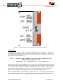
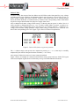
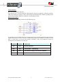
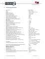
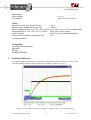
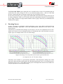
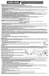
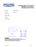
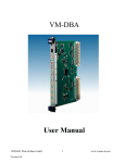
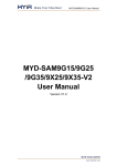
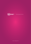
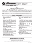
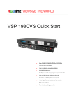
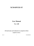
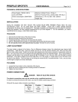
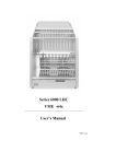
W-Ie–Ne-R
VPX3C Power Supply
3U 4HP 28 VDC Conduction Cooled
715 W VPXTM Power Supply
User’s Manual V2.1
W-IE-NE-R Plein & Baus GmbH
Rev. 2.1, March 13, 2015
1
www.wiener-d.com
General Remarks
The only purpose of this manual is a description of the product. It must not be interpreted as a
declaration of conformity for this product including the product and software.
W-Ie-Ne-R revises this product and manual without notice. Differences between the description
in manual and the product are possible.
W-Ie-Ne-R excludes completely any liability for loss of profits, loss of business, loss of use or
data, interrupt of business, or for indirect, special incidental, or consequential damages of any
kind, even if
W-Ie-Ne-R has been advises of the possibility of such damages arising from any defect or error
in this manual or product.
Any use of the product which may influence health of human beings requires the express written
permission of W-Ie-Ne-R.
Products mentioned in this manual are mentioned for identification purposes only. Product names
appearing in this manual may or may not be registered trademarks or copyrights of their respective
companies.
No part of this product, including the product and the software may be reproduced, transmitted,
transcribed, stored in a retrieval system, or translated into any language in any form by any means
without the express written permission of W-Ie-Ne-R.
W-IE-NE-R Plein & Baus GmbH
2
www.wiener-d.com
Table of contents:
1
GENERAL DESCRIPTION .................................................................. 4
2
MAIN FEATURES.................................................................................. 5
3
FUNCTIONAL DESCRIPTION ........................................................... 5
4
TECHNICAL SPECIFICATION.......................................................... 9
5
SWITCH-ON BEHAVIOR .................................................................. 10
6
DERATING CURVES .......................................................................... 11
W-IE-NE-R Plein & Baus GmbH
3
www.wiener-d.com
1
General Description
The W-Ie-Ne-R VPX3C is a high power density power supply in a 3U height 4HP width VPX
form factor designed according to VITA 62.0 VPX conduction cooled standard and largely to
VITA 46.0 VPX. It provides with 715W more than sufficient power to all main and auxiliary
power rails deliverable by VPX at high efficiency and of low ripple and noise.
Efficiencies up to 93% are reached by using newest zero voltage switching (ZVS) technologies for
the conduction cooled converters. Hence lower power losses can be more effectively distributed
through the highly heat conductive aluminum case to the wedge locks to the outer ATR case. An
integrated load sharing device allows for paralleling of two or more power supplies on customized
VPX backplanes when even more power is needed.
Our Phoenix Mecano partner HARTMANN Electronic offers a wide range of air and conduction
cooled U3 ATR chassis and backplanes for laboratory, test and also professional use for airborne
equipment. Please refer to http://www.hartmann-elektronik.de/ for more information.
Additional input filters like the DSF500 from XPPOWER™ will allow to upgrade input protection
to military levels MIL-STD 1275A-D, MIL-STD-461F, DEF-STAN 61-5 Pt 6.
W-IE-NE-R Plein & Baus GmbH
4
www.wiener-d.com
2
Main Features
• 715W continuous wattage, low noise power supply acc. to VITA 62/46 VPX specification
• 3U (half height) 4HP (slim size, 0.8” pitch) conduction cooled VPX form factor
• Zero Voltage Switching Converter Design with up to 93% efficiency @ 28V DC input
• VS1: 21A @ 12 V, VS2: 50A @ 3V3, VS3: 40A @ 5V
• AUX1: 7A @ 3V3 aux, AUX2: 4.2A @ +12Vaux, AUX3: 4.2A @ -12Vaux
• Industrial storage and operating temperatures
• Fully overall and individual power rail protections:
o Over Temperature OVT
o Over Voltage OFLW
o Under Voltage UFLW
o Over Current OC
• No input current protection, input overvoltage protection, input surge protection, reverse
polarity protection – individual external protections needed acc. to the diverse applications
3
Functional Description
All voltage ZVS converters are isolated (1500V isolation voltage) and fed via a common Filter
Network from the same 28V main supply (20V – 35V). 3V3aux is not independent but protected
by a resettable fuse (PTC). All individual output voltages (6x) are sensed by window comparators
for over- and under voltages which are monitored from a central control logic device (CPLD).
Any failure on the output voltages are signaled on the front panel by corresponding FAIL LEDs
and lead to a switch off of all voltages (by default). If all internals are normal the blue READY
LED is working. Figure 1 shows gives an overview over the front panel elements.
W-IE-NE-R Plein & Baus GmbH
5
www.wiener-d.com
Figure 1: Front panel functional elements of the VPX3C Power Supply
Control Logic:
Depending on the main bus signals also the green RUN LED goes on and the power supply tries to
start working. According to VITA 62 and VITA 46 the logic run line condition is – when “#” is
nomenclature for the negative logic main bus signals, logic negation is signaled by the “¬” sign,
and a positive logic transition by “↑”:
RUN = ( ¬ #ENABLE AND #INHIBIT AND #FAIL AND ¬INTERNAL_FAIL )
“REFRESHED AFTER FAIL WHEN”
↑ ( ¬ #SYSRESET OR ¬ #RESET_BUTTON OR POWER_ON )
This means that the if the global inhibit is not set (= released to H), whether no internal or external
failure occurs (both are released to H) the power supply starts. After some kind of failure (internal
or external) the power supply restarts by one of the following three conditions: A power cycle, a
push onto the front panel button or a remote reset via the main bus system reset (#SYSRESET).
By default all voltages go down promptly if one of the run line conditions is not met.
When an internal failure occurs the delay or failure hold time to a complete switch off of the
power supply is a half second to a second. This logic prevents any hardware from defects caused
by unsymmetrical power faults (analogue operational circuits) or partial power faults (CPUs).
W-IE-NE-R Plein & Baus GmbH
6
www.wiener-d.com
Failure LEDs:
To know exactly the reason of the last failure two fail LEDs on the front panel for every voltage
will indicate the origin. Window discriminators directly steer the upper or lower LEDs if over- or
under voltage actually takes place (OFLW, UFLW). This actual state can be watched shortly
before the failure hold time is reached and/or by flickers of the corresponding LEDs. If the failure
origin lasts longer than the hold time the power supply shuts down.
After a shutdown all under voltage LEDs must go on showing that no power is online. Now it is
easily possible to distinguish where an over- or under voltage failure occurred: A steady overvoltage LED at the corresponding power rail shows an over voltage problem, a blinking overvoltage LED an under-voltage problem. Largely under-voltage is caused by over current or over
heat of the corresponding power rail. Figure 2 gives the list of failure interpretations.
Figure 2: Failure LED failure origin interpretation
The +/- window range of the power rail is adjusted by factory to +/- 5..7 % and may be carefully
readjusted by the named front panel trimmer elements (+/- 0%..50%).
After origin of failure has removed a reset restarts the module.
Figure 3 shows an example of a manual control PCB to easily operate and view all the VPX (open
collector) backplane signals from our laboratory test rig from HARTMANN Electronic.
Figure 3: Example of a manually operated VPX bus controller
W-IE-NE-R Plein & Baus GmbH
7
www.wiener-d.com
JTAG Interface:
No USB communication interface!
The Control Logic is stored within the CPLD firmware and can be updated via the factory Micro
USB JTAG firmware connector. Hence other custom configurations like another grouping for the
power rails and failure shutdown conditions are principally possible.
DIP Switch Features:
DIP Switch S1 is internally connected in the following way:
IO1 and IO2 go to the CPLD and can be selected exclusively to install connections to the main bus
signals #GA0, UD1 or #GA1, UD2 for customization purposes (it should be avoided to switch
both 3, 4 and both 5, 6 into the ON position). Switches 1 and 2 are thought for factory or
functional test and should not be used else:
CALIBRATE LEDTEST
FUNCTION
OFF
OFF
Normal Operation
OFF
ON
Test of LEDs - 1 Hz blinking
ON
OFF
Turn OFF all voltages for external calibration
ON
ON
Override Mode: Turn on all voltages what happens
W-IE-NE-R Plein & Baus GmbH
8
www.wiener-d.com
4
Technical Specification
Form Factor
Pitch
Weight
Storage Temperature
Operating Temperature
Input to Output Insulation
Input to Output Isolation with Case
Input to Case Ground Isolation
Output to Case Ground Isolation
Case Ground to Safety Ground Resistance
Main Power
Maximum Output Power
Maximum Input Power
Maximum Dissipated Power @ max. Power
Minimum Turn ON Voltage:
Minimum Turn OFF Voltage
Hysteresis
Maximum Continuous Input Voltage
Maximum/Minimum Short Time Input Voltage (15 s)
Maximum Currents: 12V / 3V3 / 5V
Fixed Switching Frequencies: 12V / 3V3 / 5V
Peak Efficiencies: 12V / 3V3 / 5V
Minimum Capacitive Loading: 12V / 3V3 / 5V
Maximum Capacitive Loading: 12V / 3V3 / 5V
Typical Output Ripple and Noise: 12V / 3V3 / 5V
(0-20 MHz Bandwidth, 2-3x of min. capacitive loading)
Line Regulation: 12V / 3V3 / 5V
Vin=Vin,min to Vin,max, Io and Tc fixed
Load Regulation: 12V / 3V3 / 5V
Vin=Vin,nom, Io=Io,min to Io,max, Tc fixed
Controlled Overvoltage Protection: +/-12V / 3V3 / 5V
Uncontrolled
Controlled Undervoltage Protection: +/-12V / 3V3 / 5V
Temperature Protection Sensing Point (identical to case)
Maximum Internal Working Temperatures
Auxiliary +/-12V Power
Maximum Current
Fixed Switching Frequency
Peak Efficiency
Min./Max. Capacitive Loading
Typ. Output Ripple and Noise (0-20 MHz Bandwidth, 220µF load)
Load Transient Recovery Time
W-IE-NE-R Plein & Baus GmbH
9
3U VPX CC
4HP / 0.8 inch
0.6 kg / 1.23 Lbs / 21.2 oz.
-55°C to 105°C
-40°C to 85°C
1500V
550V
500V
50V
< 10 mΩ
715W
~760W
~45W
20 V
19 V
1V
35 V
36 V / - 0.5 V
21 A / 50 A / 40 A
120 kHz / 125 kHz / 130 kHz
94% / 92% / 92%
220 µF / 470 µF / 470 µF
5 mF / 50 mF / 40 mF
15 mVrms / 4 mVrms / 4 mVrms
65 mVpp / 27 mVrms / 27 mVpp
40 mV / 2 mV / 4 mV
< 0.1%
70 mV / 2 mV / 4 mV
< 0.1%
+ 0 %..+ 50 % variable by trimmer
+ 5..7 % per factory setup
14.4 V / 4.1 V / 6.1 V (hardware)
- 0 %..- 50 % variable by trimmer
- 5..7 % per factory setup
85°C
(Latching)
125°C
4.2 A
900 kHz
88%
100 µF / 4700 µF
120 mVpp / 30 mVrms
100 µs
www.wiener-d.com
Control Logic
Failure hold time
Full* Shutdown
0.5..1 s*
OVC, OVT, OFLW, UFLW
Timing
Minimum Hold up Time (at max. Power)
Minimum Input Voltage start up rise time
Output Voltage rise time: 12 V / 3V3 / 5V / 12Vaux
Startup Delay time: 12 V / 3V3 / 5V / +/- 12Vaux
Inrush Transient
Inrush Current at 500V/s Voltage Rise Time
~ 1 ms
> 50 V/s
38 V/s, 30 V/s, 27 V/s, 30 V/s (exponential)
30 ms, 28 ms, 30 ms, 80 ms
0.07 A²s || 3,3 mF external capacitance
<2A
*by default firmware
Compatibility
UL 60950 (US and Canada)
VDE 0805
IEC 950
CE Mark (EN60950)
5
Switch-On Behavior
All voltage outputs are switched on exponentially with relatively slow rise times of 30-80 ms and
do settle smooth to the final voltage without any overshoot or glitch, see fig. 3 e.g.
Figure 3: Startup Delay and Exponential Rise (orange) of VS1 = 12V Output Voltage
W-IE-NE-R Plein & Baus GmbH
10
www.wiener-d.com
The W-Ie-Ne-R VPX3C power supply has to be switched on by a source of a minimum ramp up
speed of the 28V source voltage of > 50 V/s or a maximum ramp up time < ~500 ms. If the ramp
up time is longer than half a second the control logic may stall during switch on.
If sourced by a laboratory power supply with manual hand wheels this short ramp up time may not
be safely guaranteed. In this case if possible invoke the enable/disable function of the laboratory
power supply. Instead use a high current manual switch or plug to short the just established 28V
with the power supply.
6
Derating Curves
At time of writing no conduction cooled performance curves exist which would describe the
thermal performance independent of the final implementation indifferent of the kind of ATR
chassis chosen.
Alternatively as orientation the derating of power plays a role for case temperatures above 60°C
which can be derived as rule of thumb from the air-conditioned data of the individual converters.
Figure 4 gives an example for the VS1 12V main voltage.
Figure 4: Derating curves dependent on the airflow speed and direction
by example for the 12V VS1 main voltage
Laboratory tests resulted in a good thermal performance with temperature settling times about
much more than 10 minutes and possible safe annealing temperatures at 65°C for maximum power
and power losses. For e.g. only 500W of input power consumption the heat has been found to be
easily dissipated also for non-optimal setups.
W-IE-NE-R Plein & Baus GmbH
11
www.wiener-d.com