1
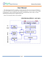
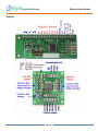
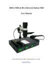
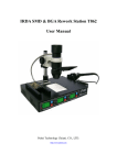
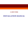
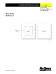
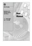
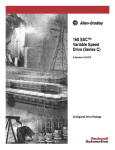
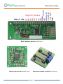
Digital Solutions Pattern Drive Module Basic Pattern Driver(60x22mm) Pattern Dirver Mini(30x30mm) Page 1 Extension Board for Mini(30x30mm) Digital Solutions Pattern Drive Module User Manual The designing idea of the module is simple, but with the use of concept of "Pattern", it give the module much powerful than original designing, it can be used in wide range of applications, such as LED strobe and drift, encode/decode, drive relay or motor according the analog input or digital input, etc. Here is the function block in the module: Page 2 Digital Solutions Pattern Drive Module The basic function is send a byte to digital output port and delay a period then output another byte to port, the current sink and source on each output BIT is @25mA, it is enough to drive a bright LED, small rely or motor, but if you need to drive high current device, you can use our Extension Board, which can drive up to 2A/20V on each channel as open source. The user can define the output value and time of the period, then upload it to module by UART/I2C/SPI communication port. A set of string that define output and delay period value are called as pattern, a pattern is start with “[“ and end with “]”, the inner of square brackets are HEX value and parentheses, 2 letters make a byte of HEX value, the parentheses are used to define the repeat partial pattern, in the following patterns, “O” represents OUTPUT value, “D” represents DELAY value,”R” represents REPEAT value,”I” represents INDEX value, must be “0~9” or “A~F”: “[OODD]”----Simplest pattern, eg. [AA03], this pattern will let module output HEX value of AA (BIN: 10101010) to output port then delay 3 circles (usually 25ms/circle), then endless to repeat the whole pattern. “[OODDOODD…]”----Serial Pattern, eg. [AA035516], this pattern will output HEX AA, delay 3 circle, then output HEX 55, delay HEX 16 circle (or 22 circles in decimal) ), then endless to repeat the whole pattern. Use “(“ and “)”, you can repeat a partial of pattern: “[(OODD…)RR…]”----Repeating Pattern, eg. [(AA035516)08(011AF23BAA01)8A], repeat 08 times of :output AAdelay 03 circlesoutput 55 delay 22 (HEX 16) circles, then repeat 138 (HEX8A) times of: output 01delay 26 circles (HEX 1A)output F2delay circles 59 (3B)output AA delay 01 circles, then endless to repeat the whole pattern. “II[(OODD…)RR…OODD…]”----Indexed Pattern, you can define a Hex number for each pattern, e.g.: FA[….], that will define the following pattern as index of 0xFA, you can run this pattern just send the index value via communication port or A/D port. You can define a very complex pattern as you wanted and needed. We also provide a tool to simulate the pattern you designed in internet browser, but we recommend use it in Microsoft IE: Pattern Drive Module Simulator The module can store up to 5KB size of pattern in its flash memory, that means it keep your pattern even power off. Page 3 Digital Solutions Pattern Drive Module The maximum useable patterns is the 256 patterns at the beginning due to it use a byte of RAM to count patterns, all patterns after 256’s are ignored. In additional of 8 BIT of output port, this module also config:1 analog input channel, 2 push button inputs and UART/I2C/SPI communication ports. 1. The analog input is a 8bit A/D converter, the A/D result can control the pattern picker to select which pattern in memory, so, use analog input can pick up one of 256 different patterns, you can use this function to make the product as such: level detector, level controller, music lighting, sound sensitive switch and more. If there are less than 256 patterns in module, the module will map the A/D result to patterns, e.g.: if only 128 patterns available, A/D result 0 and 1 will pick up pattern 0, 2 and 3 will pick up pattern 1… You also can define an index with a pattern, the first pattern without index always map to index 0, and the last pattern without index always map to index 255(0xFF). The patterns without index between 2 indexed patterns will be mapped to equal step:|e.q.: 10[A…][B…][C…][D…]20[E…], in this pattern string, the index of 1st indexed pattern is 0x10, and next indexed is 0x20, and between them, there are 3 patterns, so, the step is: (0x20-0x10)/4=4, so the 3 index mapped to 3 no index patterns are:0X14,0X18,0X1C, all A/D value between 0x14 and 0x18(exclude 0x18) will let Pattern Picker to pick [B…] pattern. 2. The 2 push button inputs are used to select or control the working mode of module, one button names “UP”, and another names “DOWN”, the 8 bit output will display the current mode when any push button pushed down: 2.1. Mode 0: Pattern Picker will pick up a pattern according the data received from communication port, then run this pattern until received new data or mode changed by press button, module will not accept save patterns command at this Page 4 Digital Solutions Pattern Drive Module mode. 2.2. Mode 1: Pattern Picker will pick up a pattern by random after each pattern displayed. 2.3. Mode 2: Run the last saved pattern, it was saved by press down both of “UP” and “DOWN” buttons. 2.4. Mode 3: Pattern Picker will pick up a pattern according the A/D result, if total patterns in memory lest then 256, it will do pattern mapping. 2.5. Mode 4 to 255: Pattern Picker will run pattern number: Mode-4, so you can choose pattern 0 to 251 use push button, but if less than 251 patterns in memory, the maximum mode will be 3+number of patterns. 3. UART/I2C/SPI communication ports: There are 3 mode on communication port that can be set by jumper on board: UART, I2C and SPI, at UART mode, it configured as 8N1 at 2400bps, at I2C mode, it configured as Slave and 7bit address is 0x27. There are 2 functions with communication ports: 3.1. Control the Pattern Picker: when module at Mode 0, all received data from communication port will drive the Pattern Picker to pick a corresponding pattern from memory, the pattern in this mode is little bit different with regular, you should define an INDEX HEX number for each pattern like this: 0A[AA05……], the number of 0A is the index of the following pattern, when module received data 0A from communication port, the Pattern Picker will pick up this pattern, if there are not find the index as same as received data in patterns, it will pick up first pattern. You can’t send command to module at this mode. 3.2. Accept command: When module Mode is other than 0, you can send command to module to configure it, few commands are available: 3.2.1. “Saveme”: This command used to upload new patterns to module, the new patterns will Page 5 Digital Solutions Pattern Drive Module overwrite the old in module, following the command key words of ”Saveme” are patterns then affix letter “X” to indicate data end: e.g.: “Saveme[AA05BB33]…..]X”. 3.2.2.“SetDely”: Set the delay circle, following 2 bytes of hex value that represent of an integer using 4 letters: e.g.: 06F4 represent the integer of 1780, the delay circle will be 25ms after sending: “SetDely06F4”, the pre-set value is 1780. 3.2.3.“SetMode”: Set the module Mode, it is same function as using push buttons, but it will give you a shortcut to set the Mode you want. 3.2.4.“SetI2CA”: This command will change the I2C address for this module, for 7 bits I2C mode, the available range of address is:0x08 to 0x78. 3.2.5.“SetSped”: Set the module internal crystal frequency, the available speeds are: 31.25KHz, 62.5KHz, 125KHz, 250KHz, 500KHz, 1MHz, 2MHz, 4MHz, 8MHz, 16MHz, 32MHz, lower frequency, lower power consumption, “0” represents 31.25KHz, “A” represents 32MHz, so the available values are:”0”,”1”,”2”,”3”,”4”,”5”,”6”,”7”,”8”,”9” and “A”. The default value is 7 (4MHz), send “SetSpedA” to module, will set the frequency to 32MHz. Please note: if the frequency of crystal changed, the delay circle period will be changed accordingly, the 25ms delay with 1780 value is under 4MHz, if you change crystal to 1MHz, the value of 1780 will delay: 25ms*4=100ms, because the frequency is 4 time slower than 4MHz. The UART speed will be changed also, it will be 300bps in speed 0 to 3 and 2400bps in speed 4 to A. Important: any push button pressed or new data received from communication port will drive the module exit running current pattern immediately. The total space used for storing patterns is 5kB, we already write some car strobe and drift patterns in it. Page 6 Digital Solutions Pattern Drive Module FEATURES: Pattern Driver: Power Supply: 3.3V to 9V. Power consumption of adapter:2mA @ 5.0V, 4MHz. Communication mode: UART/I2C/SPI, detect your setting automatically. Receiving buffer: 64 bytes. Communication signal can work on 3.3V and 5.0V TTL. Default setting: UART: baud 2400bps 8N1, I2C: 0x27 7 bits address . Extension Board: Power Supply: 5V to 20V Current: 0 to 2A open Source/Channel Page 7 8 channels digital output, current sink/source @25 mA/25 mA. 2 push button input. 1 analog input. Preloaded patterns: RC Car LED lights strobe. Patterns can be rewrite by using communication ports Pattern design/simulation tool at here Digital Solutions Pattern Drive Module Pinout: Page 8 Digital Solutions Pattern Drive Module Example Patterns: Drive 8 led drift: [000301030203040308031003200340038003] Drive 8 led strobe: [(fc01ff01)13(0301ff01)13] Drive Step motor(Bipolar, BIT0=A, BIT1=A-,BIT2=B, BIT3=B-): Set Mode to 0 (“SetMode00”), send parse number by communication port: 00[0000]01[0101]02[0501]03[0401]04[0601]05[0201]06[0A01]07[0801]08[090 1] This pattern drive step motor turn a circle, this “((0000)FF)FF” will let the module hold output 00 for a long time, you can modify it to meet you need, if the module received a new data, it will exit from this loop immediately, Use mode 0, send 01 to drive the motor forward and 02 for backward: 00[ff00]01[0101090108010A010201060104010501((0000)FF)FF]02[0101050104 01060102010A0108010901((0000)FF)FF] Turn power on/off according the analog input: 00[0000]3A[FFFF], this pattern string output 0 when A/D less 0x3A, and output 0xFF when A/D great equal than 0x3A, the output can connect a relay or DC motor, if you want drive a step motor, the pattern string should like this: 00[0000]3A[0101090108010A010201060104010501]. In order to use A/D, you need set mode of module to 3: “SetMode03”. It can be used in more applications such as music lighting, encode/decode, simple PLD, just open your idea and build that with fun. Page 9