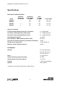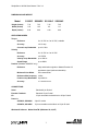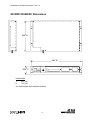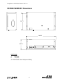
1
SimpleServo 100/200 User Manual Rev 3.4
SimpleServo®
Digital Servo Amplifier
USER'S MANUAL
MODELS:
SS108DC
SS208DC
SS108AC
SS208AC
1
SimpleServo 100/200 User Manual Rev 3.4
Copyright ©2001 by AC Technology Corporation
All rights reserved. No part of this manual may be reproduced or transmitted in any form without written
permission from AC Technology Corporation. The information and technical data in this manual are
subject to change without notice. AC Technology Corporation and its Divisions make no warranty of any
kind with respect to this material, including, but not limited to, the implied warranties of its merchantability
and fitness for a given purpose. AC Technology Corporation and its Divisions assume no responsibility for
any errors that may appear in this manual and make no commitment to update or to keep current the
information in this manual.
MotionView, SimpleServo, and all related indicia are either registered trademarks or trademarks of AC
Technology Corporation in the United States and other countries.
Printed in the United States of America.
2
SimpleServo 100/200 User Manual Rev 3.4
Table Of Contents
General Information ...................................................................................................................................... 5
Specifications ................................................................................................................................................ 6
Electrical Characteristics ........................................................................................................................... 6
Environment .............................................................................................................................................. 6
Dimensions and Weight............................................................................................................................. 7
Operating Modes ....................................................................................................................................... 7
Connections............................................................................................................................................... 7
SS108DC/SS208DC Dimensions ................................................................................................................. 8
SS108AC/SS208AC Dimensions.................................................................................................................. 9
Installation ................................................................................................................................................... 10
Wiring .......................................................................................................................................................... 11
Shielding and grounding.......................................................................................................................... 11
EMI Protection ......................................................................................................................................... 12
Enclosure................................................................................................................................................. 12
Line filtering ............................................................................................................................................. 12
Heat sinking............................................................................................................................................. 12
Line fusing ............................................................................................................................................... 13
SimpleServo Connections ....................................................................................................................... 13
Encoder Feedback .................................................................................................................................. 13
Wire size.................................................................................................................................................. 13
Connectors .............................................................................................................................................. 14
I/O details ................................................................................................................................................ 19
Operations................................................................................................................................................... 21
Configure the SimpleServo ..................................................................................................................... 21
Diagnostic LED........................................................................................................................................ 22
Enabling the drive.................................................................................................................................... 22
Appendix A.................................................................................................................................................. 23
A1. SimpleServo connections ................................................................................................................ 23
A2. SimpleServo Indexer Follower (SS208XX models only)................................................................... 26
Appendix B.................................................................................................................................................. 28
Troubleshooting....................................................................................................................................... 28
Warranty and Other Info.............................................................................................................................. 30
A. WARRANTY........................................................................................................................................ 30
B. PRODUCT CHANGES........................................................................................................................ 30
C. RECEIVING ........................................................................................................................................ 30
D. CUSTOMER MODIFICATION ............................................................................................................ 30
3
SimpleServo 100/200 User Manual Rev 3.4
Safety Warnings
• The symbol shown at left indicates an important safety consideration. Please read
this manual carefully before performing any of the procedures contained herein.
Failure to follow these instructions may result in equipment damage, fire, severe
injury, or fatality.
• Have a qualified electrical maintenance technician install, adjust and service this
equipment. Follow the National Electrical Code and all other applicable electrical and
safety codes, including the provisions of the Occupational Safety and Health Act
(OSHA), when installing equipment.
• The symbol shown at left indicates additional information, shortcuts, or tips that do
not affect the safe operation of the drive.
• Reduce the chance of an electrical fire, shock, or explosion by proper grounding,
over-current protection, thermal protection, and enclosure. Follow sound maintenance
procedures.
• It is possible for a drive to run at full speed as a result of a component failure. Please
ensure that a master switch has been placed in the AC line to stop the drive in an
emergency.
WARNING!
Hazard of electrical shock! Circuit potentials are at 115 VAC or 230 VAC above earth
ground. Avoid direct contact with the printed circuit board or with circuit elements to
prevent the risk of serious injury or fatality. Disconnect incoming power and wait 60
seconds before servicing drive. Capacitors retain charge after power is removed.
4
SimpleServo 100/200 User Manual Rev 3.4
General Information
The SimpleServo family of servo amplifiers is an economical solution to today's complex motioncontrol needs. The SimpleServo combines a Digital Signal Processor (DSP), controller, heat sink and
power supply in one standalone, DIN-rail mountable or panel-mounted unit. The SimpleServo can be
operated as a stand-alone unit or as a digital amplifier.
The SimpleServo controls brushless motors with a high switching (carrier) frequency for virtually silent
operation. Most servomotors used today require high precision control and a smooth, sinusoidally
commutated signal. An on-board DSP provides commutation by generating the three-phase sine wave,
using feedback information from an optical encoder.
The servo will accept feedback from an encoder that includes Hall sensor feedback information. It
accepts commands from a variety of sources, including analog voltage, PWM and internal reference
signals. The control will operate in current mode (torque), velocity mode, or position mode (step and
direction). Upon initial start up, the motor is commutated using the hall sensors-for the first two or three
mechanical degrees of motor rotation-to map the encoder; the Hall-effect information is unnecessary
thereafter.
The SimpleServo's built-in RS-232 serial communications port and servo control program,
MotionView™, make programming extremely simple. In fact, you could be up and running in less
than thirty minutes! Each SimpleServo unit is an amplifier, power supply, controller and heat sink
integrated into a single standalone package. The SimpleServo will only accept an encoder with Hall or an
encoder with hall-commutation tracks encoded on the feedback device.
5
SimpleServo 100/200 User Manual Rev 3.4
Specifications
ELECTRICAL CHARACTERISTICS
Drive
SS108DC
SS208DC
SS108AC
SS208AC
Maximum
Continuous
Current (AC)
5
5
Continuous
Phase Current
(AC RMS)
8A
8A
8A
8A
Peak
Current
(AC RMS)
12A
12A
12A
12A
Input Voltage
80 - 170
80 - 170
60 - 120
60 - 120
Applies to all models:
AC Output Voltage Range (Sinusoidal, Three-Phase)
0 - 120 VAC RMS
Acceleration Time Range (Zero to Max Speed)
0.1 - 5000000 Rpm/sec
Deceleration Time Range (Max Speed to Zero)
0.1 - 5000000 Rpm/sec
Speed Regulation (typical)
± 0.5 RPM
Input Impedance (+REF to COM and +REF to -REF)
47 kohms
Power Device Switching Frequency (sinusoidal commutation)
16 kHz
Encoder power supply (max)
+5 VDC @ 300 mA
Maximum encoder feedback frequency
2.5 MHz
ENVIRONMENT
Vibration
0.1 G (all frequencies)
0.5G max (20 - 50 Hz)
0.1G max (>50 Hz)
Shock
1.0 g @10 m/sec
Ambient Operating Temperature Range
0 to 40ºC
Ambient Storage Temperature Range
-10 to 70ºC
Humidity
5 - 90% non-condensing
Altitude**
1500 m/5000 ft
**derate by 1% per 300m (1000 ft) above 1500m (5000 ft)
6
SimpleServo 100/200 User Manual Rev 3.4
DIMENSIONS AND WEIGHT
Model
S108DC SS208DC SS108AC SS208AC
Height (inches)
7.35
7.35
7.35
7.35
Width (inches)
1.25
1.25
2.5
2.5
Depth (inches)
4.40
4.40
4.40
4.40
OPERATING MODES
Torque
Reference
0 ± 10 VDC or 0 to 10 VDC, scalable
Accuracy
± 0.01 amp
Current-Loop Bandwidth
up to 2.5 kHz
Velocity
Reference
0 ± 10 VDC or 0 to 10 VDC
Accuracy
± 0.5 RPM
Velocity-Loop Bandwidth
up to 300 Hz
Speed Range
up to 8000:1
Position (SS208AC SS208DC only)
Reference
Step and direction signals or Master Encoder full
quadrature signal (software selectable).
Minimum Pulse Width
250 nanoseconds
Reference Max frequency 2 MHz
Position-Loop Bandwidth Up to200 Hz
Accuracy
±1 encoder count
CONNECTIONS
Serial
Standard 9-pin D-shell
Encoder Feedback
Standard 15-pin D-shell
I/O
15-pin removable terminal block or 25-pin D-shell
Power in
SS108AC, SS208AC
3-pin AC socket
SS108DC, SS108DC
15-pin removable terminal block or 25-pin D-shell
Windows® Software: MotionViewTM (Windows 95, 98, NT)
7
SimpleServo 100/200 User Manual Rev 3.4
SS108DC/SS208DC Dimensions
DIM "A"
DIM "B"
DIM "C"
DIMENSIONS
A
4.25 [108]
B
7.25 [185]
ALL DIMENSIONS IN INCHES [MILLIMTERS]
8
SimpleServo 100/200 User Manual Rev 3.4
SS108AC/SS208AC Dimensions
DIM "A"
DIM "B"
DIM "C"
DIMENSIONS
A
4.25 [108]
B
7.25 [185]
ALL DIMENSIONS IN INCHES [MILLIMTERS]
9
SimpleServo 100/200 User Manual Rev 3.4
Installation
WARNING!
Hazard of electrical shock! Circuit potentials are at 115 VAC or 230 VAC above earth
ground. Avoid direct contact with the printed circuit board or with circuit elements to
prevent the risk of serious injury or fatality. Disconnect incoming power and wait 60
seconds before servicing drive. Capacitors retain charge after power is removed.
• The SimpleServo must be mounted vertically for safe operation at the maximum
current rating.
• Printed circuit board components are sensitive to electrostatic fields. Avoid contact
with the printed circuit board directly. Hold the SimpleServo by the case only.
• Protect the control from dirt, filings, airborne particles, moisture, and accidental
contact. Provide sufficient room for access to the terminal block.
• Mount the control away from other heat sources. Operate within the specified
ambient operating temperature range. Additional cooling with an external fan may be
recommended in certain applications.
• Avoid excessive vibration to prevent intermittent connections.
• DO NOT connect incoming power to the output motor terminals (U, V, W)! Severe
damage to the SimpleServo will result.
• Do not disconnect any of the motor leads from the SimpleServo unless power is
removed or the control is disabled. Opening any one motor lead may cause failure.
10
SimpleServo 100/200 User Manual Rev 3.4
Wiring
WARNING!
Hazard of electrical shock! Circuit potentials are at 115 VAC or 230 VAC above earth
ground. Avoid direct contact with the printed circuit board or with circuit elements to
prevent the risk of serious injury or fatality. Disconnect incoming power and wait 60
seconds before servicing drive. Capacitors retain charge after power is removed.
• Under no circumstances should power and logic wiring be bundled together.
Induced voltage can cause unpredictable behavior in any electronic device, including
motor controls.
• Use 18-28 AWG wire for reference and analog signal wiring. Use 12-16 AWG wire
for AC line (L1 and L2) and motor (Phase U, V and W) wiring.
SHIELDING AND GROUNDING
AC Technology Corp recommends the use of single-point grounding (SPG) for panel-mounted controls.
Serial grounding (a "daisy chain") is not recommended. The SPG for all enclosures must be tied to earth
ground at the same point. The system ground and equipment grounds for all panel-mounted enclosures
must be individually connected to the SPG for that panel using 14 AWG (5.5 mm) or larger wire. Refer to
Figure 6 for wiring guidelines.
In order to minimize EMI, the chassis must be grounded to the mounting panel (Figure 6). Use 14 AWG
(1.6 mm) or larger wire to join the enclosure to earth ground. A lock washer must be installed between the
enclosure and ground terminal. To ensure maximum contact between the terminal and enclosure, remove
paint in a minimum radius of 0.25 in (6 mm) around the screw hole of the enclosure.
AC Technology Corp recommends the use of the special servo cables provided by AC Technology Corp.
If you specify cables other than those provided by AC Technology Corp, please make sure all cables are
shielded and properly grounded.
It may be necessary to earth ground the shielded cable (Figure 6). Ground the shield at the SimpleServo
end and at the motor end.
If the SimpleServo continues to pick up noise after grounding the shield, it may be necessary to add an
AC line filtering devices and/or an output filter (between drive and servomotor).
11
SimpleServo 100/200 User Manual Rev 3.4
EMI PROTECTION
Electromagnetic interference (EMI) is an important concern for users of digital servo control systems. EMI
will cause control systems to behave in unexpected and sometimes dangerous ways. Therefore, reducing
EMI is of primary concern not only for servo control manufacturers such as AC Technology Corp, but the
user as well. Proper shielding, grounding and installation practices are critical to EMI reduction.
ENCLOSURE
The panel in which the servo is mounted must be made of metal, and must be grounded using the SPG
method outlined above.
Proper wire routing inside the panel is critical; power and logic leads must be routed in different avenues
inside the panel.
If you use drives that output over 8 amps, you must ensure that the panel contains sufficient clearance
above and below for the cooling fan to circulate air. Refer to Figure 3 for minimum suggested cooling air
clearance.
LINE FILTERING
In addition to EMI/RFI internal filter in the SimpleServo SS108AC/SS208AC, external filtering may be
required. High frequency energy can be coupled between the circuits via radiation or conduction. The AC
power wiring is one of the most important paths for both types of coupling mechanisms. There are many
AC line filter manufacturers whose filters can be successively integrated. AC Technology Corp
recommends Schaffner filters based on our test results.
HEAT SINKING
SimpleServos contain sufficient heat sinking in their basic configuration. There is no need for additional
heat sinking. However, drives that output more than 8 amps incorporate a heat sink cooling fan; you must
ensure that there is sufficient clearance for the cooling fan to circulate air (Figure 3). As a minimum, you
must allow an air gap of 1 inch above and below the drive.
12
SimpleServo 100/200 User Manual Rev 3.4
LINE FUSING
External line fuses must be installed on all SimpleServos. Connect the external line fuse in series with the
AC line voltage input. Table 3 lists the recommended line fuse sizes. Use fast acting fuses rated for 250
VAC or higher, and approximately 200% of the maximum phase current.
Table 2. Recommended Line Fuse Sizes.
MODEL
AC LINE FUSE SIZE
NUMBER
(AC Amps)
SS108/200
25
SIMPLESERVO CONNECTIONS
Prefabricated cable assemblies may be purchased from AC Technology Corp to facilitate wiring the
control, motor and host computer. Contact your AC Technology Corp sales representative for assistance.
ENCODER FEEDBACK
An encoder needs to have power supplied to it. SimpleServo has a +5 VDC supply voltage that is used to
power the encoder. If front-end controller power supply needs to be used to power the encoder one has
to be disconnected from SimpleServo power supply by removing connections to PWR +5V pins.
WARNING!
Use only +5 VDC encoders. Do not connect any other type of encoder to the
SimpleServo reference voltage terminals. When using a front-end controller, it is
critical that the +5 VDC supply on the front-end controller NOT be connected to the +5
VDC supply on the SimpleServo, as this will result in damage to the SimpleServo.
Note:
AC Technology Corp recommends an encoder resolution of 2000 PPR or higher for
optimum performance.
WIRE SIZE
If current draw is less than 8 amps:
16 AWG (1.0 mm) or 14 AWG (1.6 mm)
If current draw is greater than 8 amps, but less than 12 amps:
14 AWG (1.6 mm) or 12 AWG (2.6 mm)
If current draw is greater than 12 amps:
12 AWG (2.6 mm).
13
SimpleServo 100/200 User Manual Rev 3.4
CONNECTORS
AC power in (AC models only)
This power entry connector located on the bottom and made to accommodate standard 3-prong computer
AC cable plug.
WARNING!
DO NOT connect incoming power to the output motor terminals (U, V, W)!
Severe damage to the SimpleServo will result.
Note:
All conductors must be enclosed in one shield and jacket around them. The shield on
the amplifier end must be terminated at the case (chassis ground); the other end
should be properly terminated at the motor shield. To satisfy CE requirements, AC
Technology Corp recommends that you purchase SimpleServo cables for both the
motor and AC line. Contact your AC Technology Corp representative for assistance.
DC power in (DC models only)
DC power is connected via terminals 1 and 2 on TB1 connector. See description of TB1 functions below.
WARNING!
DO NOT connect incoming power to the output motor terminals (U, V, W)!
Severe damage to the SimpleServo will result.
TB1 - Power (DC units only), Motor and Fuse Connections
Table 3. TB1 Pin Assignments
Terminal Block Pin #
Name
FUNCTION
1
W (T)
+DC in (DC models only)
2
V (S)
-DC in (DC models only)
3
W (T)
Motor Power Out
4
V (S)
Motor Power Out
5
U (R)
Motor Power Out
14
SimpleServo 100/200 User Manual Rev 3.4
TB2 - Analog/Digital I/O Terminal Block
TB502 is a 15-pin quick-connect header used for analog and digital I/O functions. Refer to Table 4 for
connector pin assignments.
Table 4. TB2 Pin Assignments
Terminal Block Pin #
Name
Function
1
+Vcc
+Vcc (5mA)
2
AGND
3
-Vcc
+Vcc (5mA)
4
REF+
Positive reference input (differential)
5
REF-
Negative reference input (differential)
6
Shield
Shield connection
7
Analog Output 1
Programmable analog output
8
Analog Output 2
Programmable analog output
9
Enable
10
5 VDC out
11
GND
12
MA-/Step+
Step- (or master encoder channel A-) input2
13
MA+/Step-
Step+ (or master encoder channel A+) input2
14
MB+/Dir+
DIR+ (or master encoder channel B+) input2
15
MB-/Dir-
DIR- (or master encoder channel B-) input2
16
Ready/Fault output
Analog ground (Attach shield from signal source here)
Enable Input1
5VDC @ 10mA power out
Logic common
Ready/Fault output TTL 5V
15
SimpleServo 100/200 User Manual Rev 3.4
DS1 - Motor Feedback Input from Motor
DS1 is a 15-pin DB connector that contains connections for Hall effect sensors and encoder feedback.
Refer to Table 5 for connector pin assignments.
All conductors must be enclosed in one shield and jacket around them. AC Technology Corp
recommends that each and every pair (for example, EA+ and EA-) be twisted. In order to satisfy CE
requirements, AC Technology Corp recommends using OEM cable. Contact your AC Technology Corp
representative for assistance.
Table 5. DS1 Pin Assignments
"D"-Sub Pin #
Name
Function
1
EA+
Encoder Channel A
2
EA-
Encoder Channel A Not3
3
EB+
Encoder Channel B
4
EB-
Encoder Channel B Not
5
EZ+
Encoder Channel Z
6
EZ-
Encoder Channel Z Not
7
GND
Drive Common/Encoder Ground
8
SHLD
Shield
9
PWR
Encoder supply (+5VDC)4
10
HA-
Hall Sensor A-
11
HA+
Hall Sensor A+
12
HB+
Hall Sensor B+
13
HC+
Hall Sensor C+
14
HB-
Hall Sensor B-
15
HC-
Hall Sensor C-
16
SimpleServo 100/200 User Manual Rev 3.4
DS2 (Serial Communications Port input to Servo)
DS2 is a 9-pin DB connector that is used to communicate with a host computer. All levels must be RS232C compliant.
Table 6. TB505 Pin Assignments
"D"-Sub Pin #
Name
Function
1
Reserved
2
TX
RS232 TX
3
RX
RS232 RX
4
Reserved
5
GND
6
Reserved
7
Reserved
8
Reserved
9
Reserved
Common
WARNING!
Do not make any connection to Reserved pins!
Note:
If you purchase serial cables from a third party, you must use pass-through cable, not
Null-Modem (not crossover).
17
SimpleServo 100/200 User Manual Rev 3.4
Connectors and Wiring Notes
Note 1
The enable (Enable) pin, TB2 pin 9, must be wired to one of the output terminals on the front-end
controller, i.e., if the controller is present, it must supervise the enable function on the SimpleServo. The
SimpleServo will accept open-collector outputs for use as a switch, TTL or CMOS outputs (5V)
programmed for active low operation.
Note 2
An external pulse train signal (for "step") supplied by an external device, such as a PLC or stepper
indexer, can control the speed and position of the servomotor. The speed of the motor is controlled by the
frequency of the step signal, while the number of pulses that are supplied to the SimpleServo determines
the position of the servomotor. "DIR" input controls direction of the motion.
Note 3
The complement of A is sometimes written as not A. The B, C and Z encoder channels are annotated in a
similar fashion.
Note 4
The encoder needs to have power supplied to it. The SimpleServo has a +5 VDC supply voltage that may
be used to power the encoder.
WARNING!
Use only +5 VDC encoders. Do not connect any other type of encoder to the
SimpleServo reference voltage terminals. When using a front-end controller, it is
critical that the +5 VDC supply on the front-end controller NOT be connected to the +5
VDC supply on the SimpleServo, as this will result in damage to the SimpleServo.
18
SimpleServo 100/200 User Manual Rev 3.4
I/O DETAILS
1. Step and Direction/ Master Encoder Inputs: TB2-12,13,14,15
You can connect a master encoder with quadrature outputs or a step and direction to control position in
step/direction operating mode. You can connect a single ended or differential TTL or CMOS compatible
5V sourcing signals to the inputs. You can also connect sink open collector outputs to these inputs. See
application note in "Section A" of this manual for the connection guidelines. The function of these inputs
"Master Encoder" or "Step and Direction" is software selectable. Use MotionView set up program to
choose desirable function.
WARNING!
Inputs compatible only with 5V logic or open collector outputs. Higher voltages will
damage drive's circuit.
+5V
U1
16
R1
5.11K
R2
1K
STEP+ (TB2-12)
R3
C1
180pF
20K
R4
1K
4
12
STEP- (TB2-13)
R5
-INA
+INA
-INB
+INB
-INC
+INC
-IND
+IND
VC
C
OUTA
OUTB
OUTC
OUTD
3
13
5
11
To drive's
GN
ENABLE
ENABLE D
DS26LS32AC 8
C4
180pF
20K
1
2
15
14
6
7
9
10
R6
5.11K
R7
1K
R9
1K
DIRECTION+ (TB2-14)
R8
C5
180pF
20K
DIRECTION- (TB2-15)
R10
20K
C6
180pF
Master encoder/step and direction input circuit. (SS208 drives only)
19
SimpleServo 100/200 User Manual Rev 3.4
2. Fault Digital Output
On hardware revisions 1.06 and earlier:
TTL compatible OC output (5V logic). High when drive is at fault, low otherwise.
On hardware revision 1.07
TTL compatible output (5V logic). High when drive at fault or disabled, low otherwise.
3. Enabled digital input
This is a single-ended input, compatible with 5V TTL, open-collector sink output, and switch or relay
contacts. The input is referenced to drive logic common. These inputs are active low, i.e., connecting it to
drive logic common or supplying logic "0" referenced to drive logic common activates this input. For
connection guidelines see application note in Appendix A. See figure below for electrical diagram.
4. Analog reference input
IN+, IN- (TB2-4,TB2-5)
Analog differential input. This input will accept +/-10V single-ended voltage on IN+ or IN- input or +/-5V
differential voltage between IN+ and IN-. Both connections must be referenced to Analog Common
(TB2-2) of the drive. This input is used to control speed or torque of the motor in velocity or torque
mode. The total reference voltage as seen by the drive is the voltage difference between IN+ and IN-. If
used in single-ended mode one of the inputs must be connected to voltage source while the other one
must be connected to Analog Common. If used in differential mode, the voltage source is connected
across IN+ and IN- inputs and driving circuit common (if any) needs to be connected to drive Analog
Common terminal.
Reference as seen by drive:
Example #1:
Vin+ = 2V
Vin- =0
(connected to analog ground)
Vref = (2V) - (0V) = 2V (as seen by drive)
Example #2:
Vin+ = 2V
Vin- = -1V
Vref= (2V) - (-1V) = 3V (as seen by drive)
Example #3:
Vin+ = 2V
Vin- = 1V
Vref = (2V) - (1V) = 1V (as seen by drive)
20
Vref = (VIN+) - (VIN-)
SimpleServo 100/200 User Manual Rev 3.4
Operations
CONFIGURE THE SIMPLESERVO
Regardless of the mode in which you wish to operate, you must first configure the SimpleServo for your
particular motor, mode of operation and additional features if used.
1. Ensure that the control is properly installed and mounted. Refer to "INSTALLATION" section early in
this manual for installation instructions.
2. Perform wiring to the motor and external equipment suitable for desired operating mode and your
system requirements. Refer to system configurations diagram in Section A for various system
configuration examples.
3. Connect drive serial port DS2 to your PC serial port.
4. Turn power to the drive ON.
5. Make sure that the drive is disabled.
6. Launch MotionView software on your computer.
7. From the MotionView menu, select <Project> <Connection setup> and select "RS-232" radio button on
opened connection dialog. Click <Properties> and select the serial port number to which the drive is
connected. Leave the rest of the settings unchanged. Click <OK> to close dialogs.
8. From menu, click <Node> then <Connect drive>.
9. Set parameters for the drive according to the section "Drive configuration procedure" in MotionView
Help file. (Select <Help> <Help Topics>; expand <Quick Start> book; and select "Drive configuration
procedure").
10. After you configure the drive, proceed to tuning procedure if operating in Velocity or Step & Direction
mode. Torque Mode doesn't require additional tuning or calibration. Refer to MotionView Help file book
"Tuning" for instructions on how to tune for Velocity or Step & Direction mode.
21
SimpleServo 100/200 User Manual Rev 3.4
DIAGNOSTIC LED
There is a bi-color diagnostic LED mounted between TB1 and TB2 connectors. LED is designed to help
you monitor system status and troubleshoot any faults.
LED functions:
GREEN Blinking
- Power ON, no fault, drive disabled
GREEN Solid
- Power ON, no faults, drive enabled
RED Solid
- General Fault
RED Blinking
- Under voltage
ENABLING THE DRIVE
Regardless of selected operating mode, the SimpleServo must be enabled before it can operate.
Refer to drawing A1.3 in Appendix A for various enabling options.
22
SimpleServo 100/200 User Manual Rev 3.4
Appendix A
SIMPLESERVO SYSTEM CONNECTION EXAMPLES
A1. SIMPLESERVO CONNECTIONS
SS108
DS2
RX
RS-232 INTERFACE
RS-232
1
6
2
7
3
8
4
9
5
TX
PC COMPUTER
CONNECTOR DB9
DS1
1
9
2
10
3
11
4
12
5
13
6
14
7
15
8
A+
+5VDC (Encoder Power)
AHall AB+
Hall A+
BHall B+
Z+
Hall C+
ZHall BEncoder COM
Hall C-
CONNECTOR DB15
Motor Feedback
TB2
ANALOG/DIGITAL I/O
1
2
3
4
5
6
7
8
9
10
11
12
13
14
15
16
TB1
5
4
3
2
1
U
V
W
Motor Power
A1.1 Motor and Host computer connection
23
BLDC
MOTOR
SimpleServo 100/200 User Manual Rev 3.4
WARNING!
Hazard of electrical shock! Circuit potentials are at 115 VAC or 230 VAC above earth
ground. Avoid direct contact with the printed circuit board or with circuit elements to
prevent the risk of serious injury or fatality. Disconnect incoming power and wait 60
seconds before servicing drive. Capacitors retain charge after power is removed.o
DO NOT connect incoming power to the output motor terminals (U, V, W)! Severe
damage to the SimpleServo will result.
SS108/208DC
SS108/208AC
TB1
5
4
3
2
1
TB1
DCDC+
3
2
1
80-170VDC
100-120VAC
A1.2 Incoming power connection
24
SimpleServo 100/200 User Manual Rev 3.4
Enable options
SS108/208DC
9
TB2
1
2
3
4
5
6
7
8
9
10
11
12
13
14
15
16
PLC output
11
ENABLE
9
Relay
output
11
5V TTL/CMOS LOGIC
9
11
Controller
logic
common
A1.3 Enable options
SS108/208
SS108/208
TB2
1
2
3
4
5
6
7
8
9
10
11
12
13
14
15
16
TB2
1
2
3
4
5
6
7
8
9
10
11
12
13
14
15
16
R?
5-25K
BI-DIRECTIONAL REFERENCE
CONNECTION
R?
5-25K
SINGLE DIRECTION
REFERENCE
CONNECTION
A1.4 Analog reference for torque or velocity
25
SimpleServo 100/200 User Manual Rev 3.4
A2. SIMPLESERVO INDEXER FOLLOWER (SS208XX MODELS ONLY)
SS208
TB2
1
2
3
4
5
6
7
8
9
10
11
12
13
14
15
16
S+
STEP
S-
D+
D-
INDEXER WITH
DIFFERENTIAL
OUTPUTS
DIRECTION
A2.1 Indexer connections (differential outputs)
26
SimpleServo 100/200 User Manual Rev 3.4
SS208
TB2
1
2
3
4
5
6
7
8
9
10
11
12
13
14
15
16
STEP
OPTO OR OPEN
COLLECTOR
OUTPUTS
DIRECTION
A2.2 Indexer connections (single ended Open Collector outputs)
27
SimpleServo 100/200 User Manual Rev 3.4
Appendix B
TROUBLESHOOTING
WARNING!
Hazard of electrical shock! Circuit potentials are at 115 VAC or 230 VAC above earth
ground. Avoid direct contact with the printed circuit board or with circuit elements to
prevent the risk of serious injury or fatality. Disconnect incoming power and wait 60
seconds before servicing drive. Capacitors retain charge after power is removed.
Before troubleshooting
•
Perform the following steps before starting any procedure in this section:
•
Disconnect AC or DC voltage input from the SimpleServo. Wait 3 minutes for power to discharge.
•
Check the SimpleServo closely for damaged components.
•
Check that no foreign material has become lodged on, or fallen into, the SimpleServo.
•
Verify that every connection is correct and in good condition.
•
Verify that there are no short circuits or grounded connections.
•
Check that the drive's rated phase current and RMS voltage are consistent with the motor ratings.
For additional assistance, contact your local SimpleServo® authorized distributor.
PROBLEM
External line fuse blows
POSSIBLE CAUSE
•
Line fuses are the wrong size.
•
Motor leads or incoming power leads are shorted to ground.
•
Nuisance tripping caused by EMI noise spikes caused by poor grounding and/or shielding.
POSSIBLE CAUSE
•
Check that line fuses are properly sized for the motor being used.
•
Check motor cable and incoming power for shorts.
•
Check that you followed recommendations for proper shielding and grounding listed in section
"shielding and grounding" earlier in this manual.
28
SimpleServo 100/200 User Manual Rev 3.4
PROBLEM
Diagnostic LED is steady GREEN (enabled status) but motor does not run.
SUGGESTED SOLUTION
•
If in torque or velocity mode:
•
Reference voltage input signal is not applied.
•
Reference signal is not connected to the SimpleServo input properly; connections are open.
•
In MotionView program check <Parameters> <Reference> set to <External>
•
For Velocity mode only: In Motion View check <Parameters> <Compensation> <Velocity loop
filter> P-gain must be set to value more then 100 in order to run. Without load, motor will run with
P-gain set as low as 20, but may not run under load. If P-gain is set to 0 motor will not run at all.
•
In step and direction mode:
•
Step and Direction inputs are not wired correctly.
•
In MotionView program check <Parameters> <Step input type> is set for <S/D> if you use a stepand-direction indexer output, and <Master Encoder> if you use quadrature type output from a
master motor encoder or indexer.
•
Position loop P-gain set to 0. Set P-gain to 200 and D-gain to 200 initially to get motion. Tune
them afterwards for best performance.
PROBLEM
In velocity mode, the motor runs away.
POSSIBLE CAUSE
•
Hall sensors or encoder mis-wired.
•
SimpleServo not programmed for the connected motor.
SUGGESTED SOLUTION
•
Check Hall sensor and encoder connections.
•
Check that the proper motor is selected.
For more troubleshooting tips check our website: http://www.SimpleServo.com
29
SimpleServo 100/200 User Manual Rev 3.4
Warranty and Other Info
A. WARRANTY
AC Technology Corporation warrants the SimpleServo control to be free of defects in material and
workmanship for a period of twelve months from the date of sale to the user, or eighteen months from the
date of shipment, which ever occurs first. If the amplifier, under normal use, becomes defective within the
stated warranty time period, contact AC Technology's Service Department for instructions on obtaining a
warranty replacement unit. AC Technology Corporation reserves the right to make the final determination
as to the validity of a warranty claim, and sole obligation is to repair or replace only components that have
been rendered defective due to faulty material or workmanship. No warranty claim will be accepted for
components which have been damaged due to mishandling, improper installation, unauthorized repair
and/or alteration of the product, operation in excess of design specifications or other misuse, or improper
maintenance. AC Technology Corporation makes no warranty that its products are compatible with any
third party equipment, or to any specific application, to which they may be applied and shall not be held
liable for any other consequential damage or injury arising from the use of its products.
This warranty is in lieu of all other warranties, expressed or implied. No other person, firm or
corporation is authorized to assume, for AC Technology Corporation, any other liability in
connection with the demonstration or sale of its products.
B. PRODUCT CHANGES
AC Technology Corporation reserves the right to discontinue or make modifications to the design of its
products without prior notice, and holds no obligation to make modifications to products sold previously.
AC Technology Corporation also holds no liability for losses of any kind which may result from this action.
Instruction manuals with the most up-to-date information are available for download from the SimpleServo
website (www.simpleservo.com).
C. RECEIVING
Inspect all cartons for damage which may have occurred during shipping. Carefully unpack equipment
and inspect thoroughly for damage or shortage. Report any damage to carrier and/or shortages to
supplier. All major components and connections should be examined for damage and tightness, with
special attention given to PC boards, plugs, knobs and switches.
D. CUSTOMER MODIFICATION
AC Technology Corporation, its sales representatives and distributors, welcome the opportunity to assist
our customers in applying our products. Many customizing options are available to aid in this function.
AC Technology Corporation cannot assume responsibility for any modifications not authorized by its
engineering department.
30
SimpleServo 100/200 User Manual Rev 3.4
AC TECHNOLOGY CORPORATION
member of the Lenze Group
630 Douglas Street
Uxbridge, MA 01569
Telephone: (508) 278-9100
Facsimile: (508) 278-7873
Visit us on the web: www.SimpleServo.com
$12.00 (USA) $15.00 (Outside USA)
31