1
Indexer-Programmer-Manual.pdf REV 1.3
Indexing Digital Servo Drive
Programmer's Manual
Applied to Models:
SSi1004
SSi1004-3P
SSi1008
SSi1008-3P
SSi1010
SSi1010-3P
SSi1012-3P
1
Indexer-Programmer-Manual.pdf REV 1.3
TABLE OF CONTENTS
1. GETTING STARTED ............................................................................................................................... 4
1.1 Introduction......................................................................................................................................... 4
1.2
Programming flow overview ........................................................................................................... 7
1.3
MotionView Studio .......................................................................................................................... 8
1.4
Programming Basics....................................................................................................................... 9
1.5
Using advanced debugging features ............................................................................................ 13
1.6
Inputs and Outputs ....................................................................................................................... 14
1.7
Events ........................................................................................................................................... 18
1.8
Variables and Define statement ................................................................................................... 19
1.9
IF/ELSE statements...................................................................................................................... 20
1.10
Motion ....................................................................................................................................... 21
1.11
Subroutines and Loops ............................................................................................................. 25
2.
3.
PROGRAMMING ............................................................................................................................. 26
2.1
Introduction ................................................................................................................................... 26
2.2
User Variables .............................................................................................................................. 27
2.3
Arithmetic's ................................................................................................................................... 28
2.4
Logical expressions and operators............................................................................................... 28
2.5
Bitwise operators .......................................................................................................................... 29
2.6
Boolean Operators........................................................................................................................ 29
2.7
Comparison operators .................................................................................................................. 30
2.8
Summary of User Variables.......................................................................................................... 30
2.9
System Variables and Flags......................................................................................................... 30
2.10
System Variables and Flags Summary..................................................................................... 31
2.12
Scanned Event Statements ...................................................................................................... 39
2.13
Motion ....................................................................................................................................... 40
2.14
System Status Register (DSTATUS register) ........................................................................... 47
2.15
Fault Codes (DFAULTS register).............................................................................................. 48
2.16
Limitations and restrictions ....................................................................................................... 49
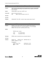
LANGUAGE REFERENCE ............................................................................................................. 50
KEYWORD
Long Name Type........................................................................................................ 50
ASSIGN
Assign Input As Index Bit Statement.................................................................................. 51
DEFINE
Define name
Pseudo-statement....................................................................................... 51
DISABLE
Turns servo OFF Statement .......................................................................................... 52
DO UNTIL
Do/Until
ENABLE
Enables servo
END
END program
Statement........................................................................................................ 52
Statement............................................................................................. 53
Statement................................................................................................... 53
2
Indexer-Programmer-Manual.pdf REV 1.3
EVENT
Starts Event handler Statement ........................................................................................ 53
ENDEVENT
End of Event handler Statement ................................................................................. 55
EVENT ON/OFF
Turn events on or off Statement............................................................................ 56
EVENTS ON/OFF
FAULT
Globally Enables/disables events Statement...................................................... 56
User generate fault
GEAR ON/OFF
Gearing Mode
GOTO
Go To
GOSUB
Go to subroutine
HALT
Statement ...................................................................................... 58
Statement ............................................................................................................ 58
Statement ............................................................................................. 59
Halt the program execution Statement .................................................................................. 59
ICONTROL ON/OFF
IF
Statement ......................................................................................... 57
Enables interface control Statement............................................................... 60
If/Then/Else
Statement .......................................................................................................... 61
MOVE
Move
Statement ............................................................................................................. 62
MOVED
Move Distance
MOVEP
Move to Position
Statement ............................................................................................... 63
Statement ............................................................................................ 64
MOVEDR
Registered Distance Move
Statement ........................................................................... 64
MOVEPR
Registered Position Move
Statement ............................................................................ 65
MDV
Segment Move
MOTION SUSPEND
Suspend
MOTION RESUME
Resume
ON FAULT/ENDFAULT
REGISTRATION ON
RESUME
RETURN
Statement..................................................................................... 66
Statement ....................................................................................... 67
On Fault
Statement ................................................................................... 68
Registration On Statement ........................................................................... 69
Resume
Statement ................................................................................................. 69
Return from subroutine
SEND/SENDTO
VELOCITY ON/OFF
Wait
WHILE/ENDWHILE
Statement ............................................................................... 70
Send network variable(s) value
STOP MOTION [QUICK]
WAIT
Statement ................................................................................................. 66
Stop Motion
Velocity Mode
Statement ......................................................... 70
Statement............................................................................. 71
Statement................................................................................ 71
Statement ................................................................................................................ 72
While
Statement ............................................................................................ 72
3
Indexer-Programmer-Manual.pdf REV 1.3
1. Getting Started
1.1 Introduction
Definitions
The SimpleServo Indexer (SSI) is a digital motion controller that will process commands within the
hardware and software limits dictated by user (wiring, configuration, parameters, program statements,
events, etc.). The output of the system is the motion(s) created in response to the command(s) input.
The SimpleServo SimpleMotion programming language (SML) provides a very flexible development
environment for creating solution to motion application. As opposed to indexers with simple command
interpreting mode, language based indexer allows you to create complex and intelligent motion, flexible
processing of inputs, complex logic decision making and program branching, timed events processing
and number of functions mostly found in PLC controllers.
The MotionView is a universal setup and configuration program used for all SimpleServo products. It has
self-configuration mechanism that adapts it to particular product automatically.
The MotionView Studio tools suite contains all the software tools needed to program and debug a
SimpleServo Indexer. MotionView Studio is a part of MotionView program. It constrains a full-screen text
editor, program compiler, status and monitor information and debugger (the tool allows you to step
through program you are developing).
The User Program (or Indexer Program) is user-developed program describing programmatic behavior
of the SSi. User Program can be stored in the text file on your PC or in SSi's memory. User Program
needs to be compiled (translated) in binary form before SSi can execute it with aid of MotionView Studio
tools.
Safety Warnings
Warning!
• Hazard of unexpected motor starting! When using the MotionView software, or otherwise
operating the SSi drive over RS-232/485 or Ethernet, the motor may start unexpectedly,
which may result in damage to equipment and/or injury to personnel. Make sure the
equipment is free to operate in this manner, and that all guards and covers are in place to
protect personnel.
Warning!
• Hazard of electrical shock! Circuit potentials are at 115 VAC or 230 VAC above earth
ground. Avoid direct contact with the printed circuit board or with circuit elements to prevent
the risk of serious injury or fatality. Disconnect incoming power and wait 60 seconds before
servicing drive. Capacitors retain charge after power is removed.
4
Indexer-Programmer-Manual.pdf REV 1.3
Getting started with SSi
Before SSi can execute motion program it has to be properly installed and configured. First time users are
encouraged to read through the appropriate sections in this manual and in SimpleServo User's Manual for
proper hardware installation and configuration.SSi programmable features and parameters
SSi drives have a number of features and parameters which can be programmed via MotionView
Software. Below is a list of programmable features and parameters specific for SSi drives in order they
appear in left tree of the MotionView. Please refer to User's Manual for details on these parameters.
Motor folder
This folder contains action button to choose particular motor. The rest of the fields contain information
about selected motor. See MotionView Help on detailed information how to setup motor.
Parameters
•
Drive mode
PIVFF mode. P(roportional) I(ntgral) V(elocity F(eed) F(orward) regulator configuration. This
mode using tunable position loop. Velocity feedback is used as dumping term and adjusted
automatically. Velocity feed forward gain is adjustable.
•
P+V mode. P(osition) +V(elocity) regulator configuration. This mode is generally slower than
PIVFF and used with lower performance mechanics. Regulator consists of outer position loop
followed by independent velocity loop followed by current loop. Position and velocity loop gains
are in tacked in this mode.
•
Current Limit
Sets RMS motor current limit. Settings per phase Amps RMS
•
Peak Current Limit
Sets RMS per phase peak current limit. This current limit is allowed for 2 Seconds. After that it will
be folded back to the level that is set by Current limit parameter.
•
Autoboot
If this option is selected after Power Up SSi will start execution of the user program. Otherwise
the program must be started manually via MotionView software or via Host Interface.
Warning!
• Hazard of unexpected motor starting! When using the MotionView software, or otherwise
operating the SSi drive over RS-232/485 or Ethernet, the motor may start unexpectedly,
which may result in damage to equipment and/or injury to personnel. Make sure the
equipment is free to operate in this manner, and that all guards and covers are in place to
protect personnel.
•
Feedback loss detection
When this option is enabled SSI will detect feedback loss, then consequently disable, and
generate fault.
•
RS485 configuration
Switches between different protocols can be used over RS485 interface. In normal mode, PPP
protocol (described in Host Interface manual) is used. "Modbus slave" is another alternative
protocol can be used to communicate with SSI drive. Modbus primarily supported for compatibility
with industry standard operator interfaces and terminals. For all other control tasks, PPP is
recommended.
5
Indexer-Programmer-Manual.pdf REV 1.3
•
Group ID
This parameter is used to combine different SSIs in functional groups. SSIs with the same group
ID can be communicated simultaneously with statement SENDTO. See statements SEND and
SENDTO for farther explanations.
•
IP Properties
Displays properties and settings for Ethernet communication port.
•
Output 0 (1,2,3) function
Every digital output except output #4 can be assigned special function
Refer to Section 1.6 to see list of available functions.
•
Hard limit switches action.
Inputs A0 and A1 serve as Hard Limit switches inputs. If <No Action> option is selected then
inputs have no effect on SSi operation as can be used as general-purpose inputs. Refer to
Section 1.6 for detail on each action item.
I/O
Limits
Position Limits
•
Position error
This parameter sets maximum allowable position error before "Position Excess Error" fault will be
generated. This parameter works in conjunction with "Max Error Time". Position Error is set in
primary motor encoder quadrature counts.
•
Position error time
This parameter sets time how long position error allowed to be bigger then limit set by "Position
error" parameter until "Position Excess Error" fault will be generated.
Compensation
Velocity Loop filter
These parameters have an effect on velocity regulator behavior when SSi placed in V+P mode. It
has no effect in PIVFF mode
•
P-gain
Velocity loop Proportional gain
•
I-gain
Velocity loop Integral gain
Refer to Section 1.10 for details on SSi position and velocity regulators behavior in both P+V and
PIVFF mode.
Position Loop filter
This parameters have an effect on position loop regulator and
•
P-gain
Position loop Proportional gain
•
I-gain
Position loop Integral gain
•
D-gain
Position loop Derivative gain
•
VFF-gain
Position loop velocity feed forward gain
•
I-limit
Position loop Integral gain influence limit
Refer to Section 1.10 for details on SSi position and velocity regulators and regulation diagrams.
6
Indexer-Programmer-Manual.pdf REV 1.3
Indexer Program
This will select the MotionView Studio section of the MotionView. Right panel is used to enter edit and
debug User Programs. Menu and toolbar will display additional features needed for program preparation
compiling debugging and loading to the SSi's memory. Motion View Studio tools and operations are
described in details in Section 1.3
Security
This option will protect source code of the User Program with password. If password was set then SSi will
ask for password before displaying User Program text. Password can be any alphanumeric string.
1.2
Programming flow overview
Welcome to SimpleServo SimpleMotion programming language (SML) - the quick and easy way to create
powerful motion application. With SML you describe your system logistics, motion, I/O processing and
user interaction programmatically i.e. creating program. The program consists from list of statements with
optional parameter(s). There are different statements for motion, processing I/O, events, program flow
control, and full set of arithmetic and logical operators. For more detail, refer to "Language Specification"
Appendix A on the back of this manual.
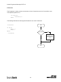
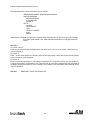
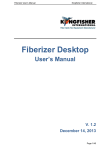
In order for SSI to understand statements, they need to be compiled (translated) to the binary machine
code. This happens when you done writing program and hit toolbar button "compile" in the MotionView
Studio environment. After compilation (translation), the binary machine codes and program text (source
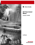
code) are both loaded into the SSI memory and stored in the internal SSI's flash memory. Fig. 2.1 below
summarizes program preparation process.
Fig. 2.1 Indexer program preparation flowchart
7
Indexer-Programmer-Manual.pdf REV 1.3
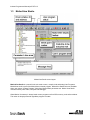
1.3
MotionView Studio
MotionView Studio screen layout
MotionView Studio is a powerful tool suite used to enter, compile, load and debug User Programs.
MotionView studio is part of the MotionView universal program. MotionView Studio becomes available
when user selects "Indexer Program" folder from MotionView's parameter tree. Motion View Studio
consists of three parts: Editor, Compiler and Debugger.
When Motion View starts, it always loads current program text from SSi's memory to the editor window.
This action is always performed regardless program run state.
8
Indexer-Programmer-Manual.pdf REV 1.3
MotionView Studio toolbar Icons From Left to Right:
Compile, Compile and load, Run, Reset Program, Stop and Disable, Single Step (Step Over), Single Step
(Step Into), Set Breakpoint, Remove breakpoint, Display Watch Window.
To load User program from PC use <Edit> <Import program from file> menu. Executing this menu loads
program from file to editor window. It doesn't load it to SSi memory yet.
To compile program and load it to SSi's memory use <Indexer> <Compile and load> menu. You can use
<Indexer> <Compile> menu to compile and check syntax errors without loading program to the SSi'
memory. If the compiler finds any syntax error, compilation stops and program will not be loaded to drive's
memory. Errors are reported in bottom portion of the screen in message area.
To save program on PC disk use <Edit> <Export program to file >.
To execute program use <Indexer> <Run> menu.
To execute program step by step use <Indexer> <Step Over> menu. SSi will execute program one
step at the time. Current program statement will be highlighted.
Breakpoint(s). It is convenient to set point in the program where you would like to stop and evaluate
some results. You can do it by pointing to lines of code you would like program to stop and hit
<Indexer><Set Breakpoint>. Red dot will mark the line showing that program will be stopped if it reaches
this line before executing it. Executing stop doesn't disable drive and all position variables are valid.
To Stop program execution and disable drive use <Indexer><Stop>. Program will stop after completing
current statement. You can resume program by hitting <Indexer><Run>.
To Reset Program execution from the beginning use <Indexer><Reset>. Program will be reset and drive
will be disabled. All position variables will no longer be valid.
1.4
Programming Basics
It is usually useful to have all the moves a machine will do, along with I/O statements, etc., in a program.
We will now explore how programs are written and used.
Make sure the indexing drive is connected to your computer and on-line.
Select <Indexer program> on the left tree. MotionView loads program from indexer memory automatically
to the right window. Note that if there is no valid program in the indexer memory window on the right will
be empty. Clear program text on in the right window if any appears then type in following program:
UNITS=1
ACCEL = 5
DECEL = 5
ENABLE
MOVED 10
MOVEDISTANCE
END
-10
9
Indexer-Programmer-Manual.pdf REV 1.3
After the text has been entered, select <Compile and load> from <Indexer> menu. After compilation is
done, message box will be displayed suggesting that our program has errors. Click <OK> to dismiss
dialog. The message window (bottom portion of your screen) will display Compiler error(s). Program line
with an error is highlighted. The line "MOVEDISTANCE -10" generated syntax error because
"MOVEDISTANCE" not a valid command. Change text "MOVEDISTANCE" to "MOVED" :
UNITS=1
ACCEL = 5
DECEL = 5
ENABLE
MOVED 10
MOVED -10
END
Select <Compile and load> again from <Indexer> menu. There should no longer be any errors. Since
program was successfully compiled, it gets loaded to the drive memory and ready to run. Run the
program by selecting <RUN> from <Indexer> menu. After program finishes, drive stays enabled. Click
<Indexer->Restart> to disable the drive and reset program execution from the start. Note that program
doesn't run itself automatically. You have to select <Indexer->Run> to run it again.
After you are done with writing the program and drive setup you can save them by using <Node|Save
configuration As.>. Indexer program is a part of drive configuration and also saved in the same file. There
will be a time when you need to import (or export) program source to the other drive or perhaps you
prepared program off-line and what to load it to drive later. You can use Indexer|Load from text file> menu
to load program source to the drive. You also can open new configuration file by selecting <Node| New
configuration file>, go to "Indexer program" folder on the left tree, and type your program in the right pane,
then save configuration file to the disk and later load it to the drive memory by selecting <Node|Load
configuration file to drive> menu. Remember that when you do so, drive configuration parameters will also
be loaded. If you want to preserve drive configuration and load a program only, use file-importing method
described above.
Units
All motion statements in the drive work with User units. Statement on first line of the test program
UNITS=1, sets the relationship between User units and motor revolutions. It simply answers the question:
"How many User units in one motor shaft revolution?" If this statement is omitted from the program, the
motor will operate with encoder counts as User units.
Time base
Time base always in seconds i.e. all time-related values are set in USER UNITS/SEC.
Enable/Disable
After execution of the statement ENABLE, drive will be enabled. If drive was disabled before execution of
that statement then the absolute position counter will be reset to zero.
Execution of the statement DISABLE will disable the drive and clear motion stack.
Attempt to produce motion when drive is disabled will generate fault.
10
Indexer-Programmer-Manual.pdf REV 1.3
Faults
When fault condition has been detected by the drive, the following events occur:
If a program is executing it is stopped. If fault handler was defined, its code starts execution.
(See below for details on fault handler). If there is no fault handler - user program is
terminated.
Fault code will be written in DFAULTS register and available to user's program. See list of
fault codes in section 2.15
Dedicated "Ready" output will turn OFF.
Any output with assigned special function "fault" will turn ON
Any output with assigned special function "ready/enabled" will turn OFF
LED's located on drive's front panel:
Ready
will turn OFF
Status
will BLINK OUT fault code or stay ON depending on fault type (See
hardware manual section "Faults" for details on fault LED).
Overcurrent will turn ON if fault was "Overcurrent"
Overvoltage will turn ON if fault was "Overvoltage"
Clearing Fault condition can be done one of the following ways:
If user program has Fault Handler section execute RESUME statement at the end (see code
example below).
Press <Indexer->Restart> if in MotionView Studio or
Send "Reset" command (command ID= 78) over the Host Interface or
Cycle power (hard reset).
Note:
You cannot execute "ENABLE" command while executing error handler code
You must leave error handler code by executing first "Reset" or "Resume <label>" statements.
Certain statements are not allowed for use in fault handler. See section 2.1 for additional details and
Language Reference section for statement ON FAULT/ENDFAULT.
11
Indexer-Programmer-Manual.pdf REV 1.3
Here is an example:
;
;This program handles faults correctly
;
UNITS=1
.
.
.
{Some initialization code}
.
PROGRAM_START:
ENABLE
MOVED 10
MOVED -10
.
.
{Program statements}
.
END
;------------------------------------------------------------------------------------;Fault Handler. If any fault occurs following program will run:
;----------------------------------------------------------------------------- ------ON FAULT
;statement starts fault handler
.
;Fault handler program. Motion
;while executing fault handler
;
;Do whatever necessary in your
;after fault is detected. Turn
.
.
{Statements}
.
RESUME PROGRAM_START
;
RESET
ENDFAULT
stopped, Drive disabled, events not scanned
statements
system
ON/OFF some outputs …etc.
;program restarts from label PROGRAM_START
;you can use this statement instead.
;to start program from the beginning
;fault handler MUST end with this statement
12
Indexer-Programmer-Manual.pdf REV 1.3
1.5
Using advanced debugging features
Click on <Indexer><Reset> menu to restart program from the beginning.
To execute program statements one at the time use or toolbar buttons or menu: <Indexer> <Step in> (or
<Step over>).
If you need to execute program up to certain statement and then stop to for example evaluate variable or
check program branching you can set breakpoints.
To set/reset breakpoint click program line you want program to stop at and click toolbar button or use
menu <Indexer><Toggle breakpoint>.
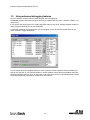
To view system and user variables values use menu <Indexer><Show Variables>. Select variables you
want to see and click on <R> (Refresh) button to refresh variables values. Note that variables values are
refreshed manually when you click on <R> button in the lower right corner or automatically when program
stops when single step completed or breakpoint is encountered.
13
Indexer-Programmer-Manual.pdf REV 1.3
1.6
Inputs and Outputs
Analog Input and Output
SSi has one analog input and one analog output directly accessible from User Program or via Host
Interface. Analog input value contained in AIN System Variable. Value returned in AIN lays in range -10 to
+10 representing voltage on analog input from -10V to +10V. Analog output can be written by writing to
System Variable AOUT. Valid range for AOUT is -10 to +10 resulting in output voltage -10V to +10V
output.
Digital Inputs numbering
SSi has 12 inputs for customer connection. Inputs are separated into three groups: A, B and C. Inputs
within the group share common terminal. Inputs are named by group name: A1-A4, B1-B4, and C1-C4.
In addition to group name, every input has its bit number range from 0 to 11in INPUTS System variable.
Each input allocates 1 bit in INPUTS variable. See table below:
Input Name
System Variable INPUTS bit #
A1
0
A2
1
A3
2
A4
3
B1
4
B2
5
B3
6
B4
7
C1
8
C2
9
C3
10
C4
11
14
Indexer-Programmer-Manual.pdf REV 1.3
Some inputs could have additional special functionality like Travel Limit, Registration etc. Special
functions (if appropriate) are selected in MotionView program for execution by Host Interface
command(s). Input functionality is summarized in the table below. Input current states are available for
programmer through dedicated System Flags or as bits of System Variable INPUTS. Table below
summarizes inputs:
Function
Special function
Input A1
Left limit switch
Input A2
Right limit switch
Input 2 A3
Input 3 A4
Common for A section
Input 4 B1
Input 5 B2
Input 6 B3
Input 7 B4
Common for B section
Input 8 C1
Master encoder input “A”
Input 9 C2
Master Encoder input “B”
Input 10 C3
Registration sensor input
Input 11 C4
Common for C section
15
Indexer-Programmer-Manual.pdf REV 1.3
Read Digital Inputs
We will now modify our test program to look for the input to go on before doing the first move, and wait for
the input to go off before doing second move. Modified program look like this:
;This program looks for the input goes on before making first move
;and looks for the input goes off before making second move
DEFINE
INPUT_ON 1
DEFINE
INPUT_OFF 0
UNITS=1
ENABLE
WAIT UNTIL IN_A1==INPUT_ON
;waits until IN_A1 is ON
;WAIT UNTIL IN_A1 ;you can use this is shorter form ;too
MOVED
10
WAIT UNTIL IN_A1==INPUT_OFF ;waits until IN_A1 is OFF
;WAIT UNTIL !IN_A1
;you can use this is shorter form ;too
MOVED -10
END
NOTE: Newly added statements are in blue.
Using inputs to generate predefined indexes
Sometimes it is convenient to use inputs to perform predefined moves (indexes).
To simplify task of inputs processing for such purposes SSi provides special system variable INDEX and
keyword ASSIGN. Keyword ASSIGN causes specific input act as particular bit of system variable INDEX .
After such assignments changes of input state will cause changes of the particular bit variable INDEX
input is assign to. Variable INDEX could be used then conveniently to select predefined move.
…{statements} …
ASSIGN
ASSIGN
ASSIGN
0 AS BIT 7
1 AS BIT 5
5 AS BIT 4
;input A1
;input A2
;input A4
…{statements} …
Variable INDEX structure after execution of the ASSIGN statements will look like this:
Note that every input can be assigned as any bit position within INDEX variable' lower 8 bits. Bits 8-31 are
not used and always set to 0. Not assign bits in INDEX variable are set to 0s.
BITS 8-31 (not used) A1 0 A2 A4 0 0 0 0
16
Indexer-Programmer-Manual.pdf REV 1.3
Limit switches input functions
Inputs A1 and A2 have secondary functions as Hard Limit Switch Negative and Hard Limit Switch Positive
respectively. From MotionVew's I/O folder you can select what type of action to perform when one of the
inputs is activated. Refer to the table below for list of possible actions.
Action
Description
Not Assigned
No action. Input functioning as regular input
Fault
Input activation cause disable and fault
Stop and Fault
Input activation causes deceleration with rate set by
System Variable QDECEL and then disable and fault
Digital Outputs Control
There are total of 5 outputs. 4 are general purpose programmable and 1 dedicated.
Dedicated output turns ON when system status is READY and cannot be controlled from the program.
The rest of 4 outputs could be assigned special function through MotionView or executing Host Interface
commands. You can turn ON (set) or turn OFF (clear) particular output by writing to corresponding
System Flag or setting particular bit(s) in System Variable OUTPUT. Output can be control by program if
it is not assigned to one of the special functions. In this case, output is controlled internally and changing
its value from within program (or via Host Interface) has no effect on output. Table below summarizes
outputs functions and corresponding flags in DSTATUS System Variables. To set output write to its flag
any non 0 value (TRUE). To clear output write to its flag 0 (FALSE). You also can use flags in expression.
If expression evaluates to TRUE then output will be turned ON. It will be turned OFF otherwise.
Example:
;Following code sets and clears some outputs
;
OUT1 =1
;turn OUT1 ON
OUT2=10
;any value but 0 turns output ON
OUT3=0
;turn OUT3 OFF
OUT2 = APOS>3 && APOS<10
;ON when position within window
;OFF otherwise
Function
Related Flag # from DSTATUS System Variable
Motion Complete
25
In Position Window
5
Fault 3
In Motion
Inverse of flag 25
Ready 0
17
Indexer-Programmer-Manual.pdf REV 1.3
1.7
Events
Scanned Events
A Scanned Event is a small program that runs independently of the main program. To establish Scanned
Event we need to specify condition to scan in event header and write statements to perform when
condition is true. Finally we need to turn Event On by executing Event <eventname> ON statement. To
learn more about Scanned Events refer to the Section 2.12. We will use Scanned Events to implement a
programmable limit switch. A programmable limit switch is a mechanism that can be programmed to turn
on at specific position. We will set up a Scanned Event to check if the current position (system variable
APOS) is greater than or equal to a given value (3) and less than or equal to another given value (6). If it
is, Output 0 is turned ON. Otherwise it is OFF.
UNITS =1
;
;
EVENT
;256uS
InLimits
1==1
; always true so event scanned every
;
OUT1= APOS>=3
&&
APOS<=6
;
ENDEVENT
;
ENABLE
EVENT InLimits ON
;Make some moves so we can go
MAXV=200
ACCEL=10
DECEL=10
;same
ProgramStart:
MOVE 10
MOVE 0
GOTO ProgramStart
END
;APOS and TPOS are initialized to 0
;turns Event InLimits ON
in and out ;of the specified limits of
;200 Rpm
;10 Rps*s
as ACCEL
;move to 10 revs position
;move back to 0
;loop it forever
When this program run motor will move 10 revs CW and than move back to initial position. Output 0 will
be ON during motor shaft position within the window 3 to 6 revs inclusively and low all the other times.
There are certain restrictions when writing code for event handlers. Refer to section 2.1 for additional
information on scanned events.
18
Indexer-Programmer-Manual.pdf REV 1.3
1.8
Variables and Define statement
In the previous program for programmable limit switch we used hard coded numbers 3 and 6 :
EVENT
InLimits
;
OUT1=APOS>=3 &&
ENDEVENT
ALWAYS
;scanned every 256uS
APOS<=6
;Hard Coded Limit values
Using hard coded numbers is fine as long as these numbers are known at the moment when you
preparing program. (Or we call it "at compile time").But what if limits has to be calculated based on some
parameters unknown before program run? (i.e. home origin, material width etc.). Then you can use User
Variables instead of hard coded values. SSi has 32 User Variables available for calculation and storage
of intermediate data. Let's use variable V1 and V2 to hold the values of lower and upper travel limits:
;Modified program:
EVENT
InLimits
ALWAYS
;scanned every 256uS
;
OUT1= APOS>=V1 && APOS<=V2 ;Variables hold Limit values
ENDEVENT
It might be difficult to remember that V1 is the lower and V2 is upper travel limit later on. The DEFINE
statement lets a programmer define a meanful name to a variable. The program looks like this:
DEFINE
DEFINE
Define
EVENT
LowerLimit
UpperLimit
ALWAYS
InLimits
V1
V2
1
ALWAYS
;
OUT0=APOS >= LowerLimit &&
;named by DEFINE statement
ENDEVENT
;name alias for V1
'name alias for V2
;scanned every 256uS
APOS <= UpperLimit ;Variables V1 V2
19
Indexer-Programmer-Manual.pdf REV 1.3
1.9
IF/ELSE statements
IF/ELSE statement allows you to execute one or more statements conditionally. You can use IF or
IF/ELSE construct:
Single IF example:
;Implementing counter modulo reset:
Again:
V1=V1+1
IF
V1>10
V1=0
ENDIF
GOTO Again
END
IF/ELSE example:
;Assign value to variable conditionally
IF V1>3
V2=1
ELSE
V2=0
ENDIF
IF or IF/ELSE construct must end with ENDIF keyword
20
Indexer-Programmer-Manual.pdf REV 1.3
1.10 Motion
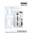
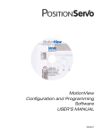
SSi position and velocity regulator's diagram
Position Feedback
Kff term
Position
Command
Current
limiter
P term
I term
I term Limit and
unti wind-up
Biquad
covergence
filter
Scale factor
P+V Mode
PIVFF Mode
PIVFF Mode
To Torque amplifier
P+V Mode
Velocity Command
I term
Biquad
convergence
filter
Current
limiter
P term
I term Limit and
unti wind-up
Velocity
estimator
Mechanical Velocity feedback
Primary
Encoder
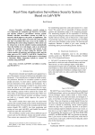
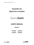
"Position Command" in regulator's diagram is produced by trajectory generator. Trajectory generator
processes generated motion commands, produced by User's program motion statements, in order to
calculate position increment or decrement or also called "index" value for every servo loop. This way
target (or theoretical) position supplied to regulator input. The main job of the regulator is to control motor
shaft torque and velocity such way that actual position of the motor shaft, measured by processing
motor's encoder position feedback, matches target position as closed as possible. Of course there is
always will be the error in position following. Such error called "Position Error" and is expressed as:
Position Error = Target Position - Actual Position
When Position Error exceeds certain threshold value "Position Error Excess" fault #7 will be generated.
You can set allowable Position Error limit and Position Error Time (how long is a delay before fault
generated). These parameters can be set only using MotionView software.
Motion Modes
There is three modes SSi can operate in: Indexing (profiling) mode, Velocity mode and Gear mode.
Indexing is a default mode. All user program generated moves are executed in this mode. Velocity and
Gearing mode are covered in details in section 2.13.
21
Indexer-Programmer-Manual.pdf REV 1.3
Point To Point Moves
SSi supports two types of moves: absolute and incremental. The statement MOVEP (Move to Position) is
used to make absolute move. The statement MOVED (Move Distance) makes incremental (or relative )
move from current position.
MOVEP and MOVED statements generate what is called a trapezoidal point to point motion profile: the
motor accelerate using the current acceleration setting to a default top speed and then decelerate at the
right time to arrive at desired position. If the distance to be moved is fairly small, a triangular move profile
will be used: the motor will accelerate for the half the move and decelerate for the other half of the move,
but never reach the top speed.
Segment moves
MOVED and MOVEP commands are simple and useful, but if the required move profile is more complex
then a simple trapezoid, MDV (segment) moves can be used.
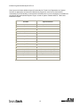
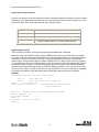
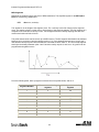
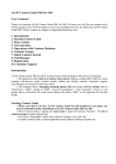
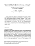
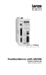
The profile shown below can be broken up to 8 MDV moves. The first segment would define the distance
between point 1 and point 2 and the velocity at point 2. So, if the distance between point 1 and 2 was 3
units and the velocity at point 2 was 56 RPM, the command would be: MDV 3 , 56. The second segment
would give the distance between point 2 and 3 and the velocity at point 3, and so on. Any profile can be
programmed using MDV moves.
22
Indexer-Programmer-Manual.pdf REV 1.3
From the following table, write a program to execute the move profile shown, and run it.
Segment Number
Distance moved during
segment
Velocity at the end of
segment
1
3
56
2
3
12
3
4
16
4
2
57
5
2.5
57
6
3
11
7
5
20
8
5
0
-
-
-
;Segment moves
MDV
3 , 56
MDV
3 , 12
MDV
4 , 16
MDV
2 , 57
MDV
2.5 , 57
MDV
3 , 11
MDV
5 , 20
MDV
5 , 0
END
Registration
Both type of moves absolute and incremental could be used for registration moves. Statements MOVEPR
and MOVEDR perform registration moves. Statements have two arguments. First argument specifies
move distance or position and second specifies displacement from registration position if it is detected.
SSi has input which registration sensor could be connected to. Move initiated by <<MOVEDR 10,30 >>
will result in incremental motion to 10 user units if registration mark is not met. Otherwise motion will
continue to "Registration position" + 30 user units.
23
Indexer-Programmer-Manual.pdf REV 1.3
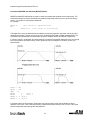
S-Curve Acceleration
Very often it is important for a move profile to be as smooth as possible. This could be to minimize the
wear on a machine, or it could be that a smooth profile is critical to the successful completion of an
operation. To perform smooth motion profiles, the Sis supports S-curve acceleration.
With normal, straight line acceleration, the axis is accelerated to the target velocity in a linear fashion.
S curve acceleration accelerates axis slowly at the first, twice as fast as the straight line acceleration in
the middle, and then slowly stops accelerating. With straight line acceleration, the acceleration changes
abruptly and then at the end of acceleration period, changes abruptly again to no acceleration. With Scurve acceleration the acceleration gradually builds to the peak value the gradually decreases to no
acceleration. The disadvantage with S-curve acceleration is that for the same acceleration distance the
peak acceleration is twice that of straight line acceleration - which often requires twice the peak torque.
Notice that the axis arrive at the target position at the same time regardless which type of acceleration is
used.
To use S-curve acceleration in MOVED,MOVEP or MDV statement requires only the additional ",S" at the
end of the statement.
Examples:
MOVED
10 , S
MOVEP
10 , S
MDV
10,20,S
MDV
10,0,S
Motion Queue
By default when program executes MOVE, MOVED or MOVEP statements, it waits motion complete
before to go to the next statement. This effectively will suspend the program until requested motion is
done. Note that event are not suspended however and keep on executing in parallel. While this is
convenient for simple motion program it could be a troublesome when trying to do monitoring and
controlling I/O at the same time when execute motion. Consider a short program:
;This program monitors I/O in parallel with motion:
START:
MOVED 100,C
;start moving max 100 revs
WHILE FLAG_MOTION
;while moving
IF IN_A2 == 1
;if sensor detected
OUT1=1
;turn ON output for
WAIT TIME 10
;10 mS
OUT1=0
;turn output OFF
ENDIF
ENDWHILE
;Return mechanism back
MOVED
-100
;Return back
WAIT TIME 1000
;wait time
GOTO START
;and start all over
END
This program starts motion and moves for maximum 100 revs. While in motion if it sees sensor (or switch)
it turns output for 10mS. The programs able to look for the sensor while executing motion because of ",C"
modifier for MOVED statement. Without this modifier program would be suspended until all motion is
done making impossible to look for the sensor on input #1. After it travels the full distance it returns back
to initial position and process repeats. This program could be used for simple paint mechanism which
turns ON paint spray as soon as part edge (or part guide) crosses the sensor(s).
24
Indexer-Programmer-Manual.pdf REV 1.3
On the other hand, MDV statement execution never suspends the program because each individual
statement sets portions of motion profile. Every motion profile or portion of (in case of MDV statement)
generated by motion statements MOVEP,MOVED or MDV first go to motion stack and than executed one
by one. In the other hand if statement doesn't have ",C" modifier motion profile generated by this
statement goes to motion stack and program suspended until this profile has been executed.
1.11 Subroutines and Loops
Subroutines
Often it is necessary to repeat a series of steps in several places in a program. Subroutines can be useful
in such situations. The syntax of a subroutine is simple. Subroutines must be placed after the main
program (after END statement), must start with subname: label (where subname is name of subroutine),
and must end with a statement RETURN.
Note that it can be more than one RETURN statement in a subroutine. Subroutines are called using the
GOSUB statement.
Loops
SML language supports WHILE/ENDWHILE block statement which can be used to create repetition
loops. Note that IF-GOTO statements can also be used to create loops.
Following example shows a subroutine called MDS and WHILE/ENDWHILE block statement to implement
looping.
DEFINE
DEFINE
DEFINE
DEFINE
LOOPCOUNT
LOOPS
dist
repetitions
V1
10
V2
V3
repetitions=0
MainLoop:
LOOPCOUNT=LOOPS
dist=10
WHILE
LOOPCOUNT
;inner performs LOOPS times
dist=dist/2
GOSUB MDS
;Call to subroutine
WAIT
100
;this executes when returned
;from subroutine
LOOPCOUNT=LOOPCOUNT-1
;decrement loop counter
ENDWHILE
repetitions=repetitions+1
;outer loop
IF
repetitions < 5
goto main
ENDIF
END
;-------------------Main program End--------------------------------;-------------------------------------------------------------------;Motion subroutine
;----------------------------------------------------------------------------MDS:
V4=dist/3
MDV
V4, 10
MDV
V4,10
MDV
V4,0
RETURN
25
Indexer-Programmer-Manual.pdf REV 1.3
2. Programming
2.1
Introduction
One of the most important aspects of programming is developing a structure for the program. Before you
begin to write a program, you should develop a plan for that program. What tasks must be performed? In
what order do they need to be performed? What things can be done to make the program easy to
understand and to be maintained by others? Are there any procedures that are repetitive?
Most programs are not a simple linear list of instructions where every instruction is executed in exactly the
same order each time program run. Programs need to do different things in response to external events
and operator input. SML contains program control structures instructions and scanned event functions
that may be used to control the flow of execution in an application program.
Control structure instructions are the instructions that cause the program to change the path of execution.
Scanned events are instructions that execute at the same time as the main body of the application
program.
Program Structure
SML programs are divided into four distinct sections:
Header
DEFINE
ASSIGN
name
Vn
Events description
EVENT
name <condition>
…statements
ENDEVENT
Main Program Body
…statements
;End of main body statements
END
Subroutines
SUB
subname
…statements
RETURN
Fault handler
ON FAULT
…statements
RESUME <label>
ENDFAULT
26
Indexer-Programmer-Manual.pdf REV 1.3
The header section of the program contains definitions of the names for user variables and constants
used in the program. If none of these are used in a program the header section is not required.
Events sections contain all scanned events sections. Remember to execute EVENT <eventname> ON
statement in main program to enable events. Not all statements are possible to use within event body.
See EVENT/ENDEVENT statement in Language Reference section for details on the statements
restrictions. While GOTO statement is prohibited within event code, you can use JUMP statement to jump
to code in main program body. You can use such technique if you need to change program flow by
occurrence of the event. See JUMP statement in Language Reference section for details.
The main program body of the program contains the main part of the program, which can include all
motion and math statements, labels, I/O commands and subroutine calls. Main body has to be finished
with END statement.
Subroutines are routines hat are called from the body of the program. When a subroutine is called,
program execution is transferred to the subroutine until a RETURN statement occurs. Then, program
execution returns to the body of the program following the GOSUB statement.
Fault handler is the special section of the program embraced with ON FAULT and ENDFAULT
statements. When any fault occurred normal program flow will be interrupted and statements in fault
handler will start to execute. When fault occurs the motion (if any) will be stopped and drive will be
disabled. Events scanning will be stopped until program exits fault handler. Fault handler can be
terminated two ways:
Using RESUME <label>.Statement will end fault handler end start execute code from location named in
<label>. Using RESET statement. Statement will reset program execution from first statement.
If ENDFAULT statement is met before RESET or RESUME statements user program will be terminated.
Fault handler should be kept as short as possible. If You need extensive processing of the fault create
such code in main program and make RESUME <label> as soon as possible. While fault handler is active
events are not being processed and detection of the other faults is not possible. Not all statements can be
used while program in the fault handler. See ON FAULT/ENDFAULT statement description in Language
Reference section for details.
Comments are allowed in any section of the program and are preceded by a semicolon. They may occur
on the same line as an instruction, or on a line that contains only the comment. Any text following a
semicolon on a line will be ignored by the compiler.
2.2
User Variables
SML supports a fixed set of variables that the programmer can use to store data and perform arithmetic.
All user variables are of a single type(see below). Single type variables facility (typeless variables) relieve
programmer of the task to remember and apply conversion rules between types, thus greatly simplifying
programming.
Since SML is typeless language, there is no special type for Boolean type variables (variables that can be
only 0 or 1). Regular variables are used to facilitate Boolean variables. When assigning 0 value to
variable it is evaluated as "FALSE" in logic equations and non 0 value evaluates as "TRUE".
In addition to the user variables, system variables are also supported.
System variables are dedicated variables that contain particular values. For example, APOS contains
actual position of the motor shaft. System variables are discussed later in chapter "System Variables and
Flags".
Scope
SML variables are available system wide. Each of the variables can be read and set from any user
program, subroutine or Host Language Command at any time. There is no provision to protect a variable
from change. This is referred as global scope.
27
Indexer-Programmer-Manual.pdf REV 1.3
Volatility
All Sis variables are volatile i.e. they don't maintained their values after power is removed. After power up
values of all variables are set to 0. Program load or reset doesn't change variables values.
Flags, Resolution and Accuracy
As mentioned before you can use any variable as flags in logical expressions and as conditions in
conditional expressions. Flags are often used to indicate that some event has occurred, logic state of
input has changed or that the program has executed to a particular point. Variables with non 0 value are
evaluated as "TRUE" and with 0 value as "FALSE".
Variables are stored internally as 4 bytes (double word) for integer portion and 4 bytes (double word) for
fractional portion. This way every variable in SSi system stored as 64 bit in 32.32 fixed point format.
Maximum number can be represented by this format is +/- 2,147,483,648. Variable resolution in this
format is 2.3E-10.
2.3
Arithmetic's
Four arithmetic functions are supported. Constants, User and System variables could be part of arithmetic
expressions.
Examples.
V1 =
V1 =
V2 =
APOS
V5 =
V1+V2
;Add two user variables
V1-1
;Subtract constant from variable
V1+APOS
;Add User and System (actual position) variables
= 20
;Set System variable
V1*(V2+V3*5/2+1) ;Complicated expression
Operator
Symbol
Addition
+
Subtraction
-
Multiplication
*
Division
/
Result overflow for "*" and "/" operations will cause Arithmetic overflow fault # 19. Result
overflow/underflow for "+" and "-" operations does not cause arithmetic fault.
2.4
Logical expressions and operators
Bitwise, Boolean, and comparison operators are considered as Logical Operators. Simply put they are the
operators which operate on logical values of the operands. There are two possible values for logical
operand: TRUE and FALSE. Any value contained in User or System variable or flag treated as TRUE or
FALSE with these types of the operators. If variable value equal 0 it is considered FALSE. All the other
values (non 0) including negative numbers are considered TRUE.
28
Indexer-Programmer-Manual.pdf REV 1.3
2.5
Bitwise operators
The following bitwise operators are supported
Operator
Symbol
AND
&
OR
|
XOR
^
NOT
!
Both User or System variables can be used with these operators.
Examples:
V1
IF
V1
V1
V1
2.6
= V2 & 0xF
;clear all bits but lowest 4
(INPUTS & 0x3)
;check inputs 0 and 1
= V1 | 0xff
;set lowest 8 bits
= INPUTS ^ 0xF
;invert inputs 0-3
= !IN_A1
;invert input 0
Boolean Operators
These operators are used in logical expressions.
Operator
Symbol
AND
&&
OR
||
NOT
!
Examples:
IF APOS >2 && APOS <6 || APOS >10 && APOS <20
. {statements if true}
ENDIF
Above example check if APOS(actual position) within one of two windows:
2 to 6 units or 10 to 20 units. In plain English:
"If
APOS more then 2 AND APOS less then 6
OR
APOS more then 10 AND APOS
less then 20 -----à then evaluate to TRUE. Otherwise it is FALSE"
29
Indexer-Programmer-Manual.pdf REV 1.3
2.7
Comparison operators
Following operators are supported:
Operator
Symbol
more
>
less
<
Equal or
more
>=
Equal or
less
=<
Not Equal
<>
Equal
==
Examples:
IF APOS <=10
IF APOS > 20
IF APOS ==5
IF V1<2 && V2 <>4
2.8
V0-V3
N0-N31
2.9
Summary of User Variables
User defined variables. Variables can hold any numeric value including logic (Boolean
0 - FALSE and non 0 - TRUE) values. They can be used in any valid arithmetic or
logical expressions.
User defined network variables. Variables can hold any numeric value including
logic(Boolean 0 - FALSE and non 0 - TRUE) values. They can be used in any valid
arithmetic or logical expressions. Variables can be shared across Ethernet network
with use of statements SEND and SENDTO.
System Variables and Flags
System variables are variables that have a predefined meaning. In most cases the value of these
variables can be read and set in your program. Many of these variables can be set in folders of Motion
View. Some of the variables are read only write only or read and write. Read only variables cannot be
used as left value of the expression. For instance INPUT = 5 is illegal because you can not set inputs.
System Flags are the special System variables that can only have values 0 or 1. As an example, IN_A1 is
the system flag and reflects state of the digital input1. Input only can be 0 or 1 and therefore flag IN_A1
will have values 0 or 1.
30
Indexer-Programmer-Manual.pdf REV 1.3
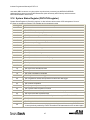
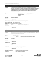
2.10 System Variables and Flags Summary
Below is the table of System Variables and Flags, sorted by type. Variables can be Read-Only (R) or
Read/Write (R/W) types. System Flags are always Read Only (R).
Variable
Access
Variable Description
NOTE 1
User Units scale.**
Units
UNITS
R/W
UserUnits/Rev
APOS
R/W
Actual motor position
User Units
TPOS
R
Theoretical/commanded position
User Units
TV
R
Commanded velocity in
User Units/Sec
RPOS
R
Registration position. Valid when system flag
F_REGISTARTION set
User Units
TA
R
Commanded acceleration
INPOSLIM
R/W
Maximum allowable deviation of position for
INPOSITION Flag to remain to be set
User Units
MAXV
R/W
Maximum velocity for motion commands
User Units/Sec
ACCEL
R/W
Acceleration for motion commands
User Units/Sec
2
DECEL
R/W
Deceleration for motion commands
User Units/Sec
2
QDECEL
R/W
Quick Deceleration for STOP MOTION QUICK
statement
User Units/Sec
2
VEL
R/W
Set Velocity when in velocity mode
User Units/Sec
GRATIO
R/W
Gear Ratio between master encoder
and motor
-
MEPPR
R/W
Master Encoder resolution.
Pulses
PGAIN_P
R/W
Position loop P-gain
-
PGAIN_I
R/W
Position loop I-gain
-
PGAIN_D
R/W
Position loop D-gain
-
PGAIN_VFF
R/W
Position loop VFF (velocity feed forward) gain
-
PGAIN_ILIM
R/W
Position loop I gain limit
-
VGAIN_P
R/W
Velocity loop P-gain
-
VGAIN_I
R/W
Velocity loop I-gain
-
INPUTS
R
Digital Inputs states. First 12 bits corresponds
to 12 SSi inputs
-
OUTPUTS
R/W
Digital outputs. First 5 bits represents outputs
From #0 to #4
-
INDEX
R/W
Lower 8 bits are used. See ASSIGN statement
for details.
-
PHCUR
R
Motor phase current
A(mpere)
DSTATUS
R
Status flags register
-
DFAULTS
R
Fault code register
-
AIN
R
Analog input. Scaled in volts.
Range form –10 to +10
V(olt)
AOUT
R/W
Analog output value in Volts.
NOTE 2
Valid range from –10 to +10 (V)
V(olt)
31
Indexer-Programmer-Manual.pdf REV 1.3
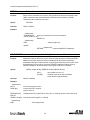
NOTE 1
If 0 (Zero) value assigned to variable UNITS set USER UNITS to QUAD ENCODER COUNTS. This is
default units at the start of the program before UNITS=<value> executed.
NOTE 2
Any value outside +/- 10 range assigned to AOUT will be automatically trimmed to that range.
Example:
AOUT=100 , AOUT will be assigned value of 10.
V0=236
VOUT=V0, VOUT will be assigned 10 and V0 will be unchanged.
System Flags
IN_A1-4, IN_B1-4,
IN_C1-4
R
Digital inputs . TRUE if input active, FALSE
otherwise
OUT1,OUT2,OUT3
OUT4, OUT5
W
Digital outputs OUTPUT1- OUTPUT5
F_ICONTROLOFF
R
Interface Control Status (ON/OFF)
#27 in DSTATUS register
F_IN_POSITION
R
TRUE when Actual Position (APOS) is within limits
NOTE 1
set by INPOSLIM variable and motion completed
F_ENABLED
R
Set when drive is enabled
F_EVENTSOFF
R
Events Disabled Status (ON/OFF)
#30 in DSTATUS register
F_MCOMPLETE
R
Set when motion is completed and there is no motion
commands waiting in the Motion Queue
F_MQUEUE_FULL
R
Motion Queue full
F_MQUEUE_EMPTY
R
Motion Queue empty
F_FAULT
R
Set if any fault detected
F_ARITHMETIC_FLT
R
Arithmetic fault
F_REGISTRATION
R
Set when registration mark was detected. Content
RPOS variable is valid when this flag is active. Flag
resets by any registration moves MOVEPR,MOVEDR
or by command REGISTARTION ON
F_MSUSPENDED
R
Set if motion suspended by statement MOTION
SUSPEND
32
Indexer-Programmer-Manual.pdf REV 1.3
NOTE 1
Flag logic is shown below :
If
TPOS-INPOSLIM < APOS <
TPOS+INPOSLIM
&& F_MCOMPLETE && F_MQUEUE_EMPTY
F_IN_POSITION = TRUE
Else
F_IN_POSITION = FALSE
End If
For VELOCITY and GEAR mode F_MCOMPLETE and F_MQUEUE_EMPTY flags are ignored and
assumed TRUE.
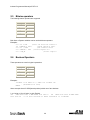
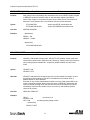
2.11
Control Structures
Control structures allow you to control the flow of your program's execution. Most of the power and utility
of any programming language comes from its ability to change statement order with structure and loops.
DO/UNTIL structures
This statement is used to execute a block of code one time and then continue executing that block until a
condition becomes true (satisfied). The difference between DO/UNTIL and WHILE statements is that the
DO/UNTIL instruction tests the condition after the block is executed so the conditional statements are
always executed at least one time. The syntax for DO/UNTIL statement is:
DO
…statements
UNTIL
<condition>
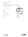
The following flowchart and code segment illustrate the use of the DO/UNTIL statement.
… statements
Start
DO
UNTIL
MOVED 3
WAIT TIME 2000
IN_A3
Move DIstance 3
inches Delay 2
seconds
…statements
Is input 2 ON?
YES
End
33
NO
Indexer-Programmer-Manual.pdf REV 1.3
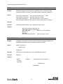
WHILE Structure
This statement is used if you want a block of code to execute while a condition is true.
The syntax for the WHILE instruction is:
Start
WHILE <condition>
…statements
Move DIstance 3
inches Delay 2
seconds
ENDWHILE
…statements
WHILE
IN_A3
Is input 2 ON?
MOVED
3
WAIT TIME
2000
ENDWHILE
YES
…statements
End
34
NO
Indexer-Programmer-Manual.pdf REV 1.3
Subroutines
A subroutine is a group of SML statements that is located at the end of the main body of the program. It
starts with label which is used by GOSUB statement to call this subroutine and ends with RETURN
statement. The subroutine is executed by using GOSUB statement in the main body of the program.
Subroutines can not be called from EVENT or FAULT handlers.
When a GOSUB statement is executed, execution is transferred to the first line of the subroutine. The
subroutine is executed until a RETURN statement is met. When the RETURN is executed, program
execution returns to the program line in the main program following GOSUB statement. Subroutines may
have more then one RETURN statement in its body.
Subroutine may be nested for up to 16 times. Only the remaining body of the program may contain a
GOSUB statement. Refer to Part 3 Language Reference for more detailed information on the GOSUB
and RETURN statements. The following flowchart and code segment illustrate the use of subroutines.
…statements
GOSUB CalcMotionParam
MOVED V1
OUT2=1
…statements
END
;Subs usually located after END
;statement of main program
;
CalcMotionParam:
V1 = (V3*2)/V4
RETURN
35
Indexer-Programmer-Manual.pdf REV 1.3
IF Structure
The if statement is used to execute an instruction or block of instructions one time if a condition is true.
The simplified syntax for IF is:
IF condition
…statement(s)
ENDIF
The following flowchart and code segment illustrate the use of the IF statement.
Start
…statements
IF IN_A2
OUT2 = 1
MOVED 3
ENDIF
Input1 ON?
Yes
..statements
Set Output 2 ON
Move Distance 3
inches
NO
End
36
Indexer-Programmer-Manual.pdf REV 1.3
IF/ELSE Structure
The IF/ELSE statement is used to execute an statement or a block of statements one time if a condition is
true and a different statement or block of statements if condition is false.
The simplified syntax for the IF/ELSE statement is:
IF <condition>
…statement(s)
ELSE
…statement(s)
ENDIF
The following flowchart and code segment illustrate the use of the IF/ELSE instruction.
Start
…statements
IF IN_A2
OUT2=1
Input1 ON?
MOVED 3
Yes
ELSE
OUT2=0
MOVED 5
No
ENDIF
..statements
Set Output 2 OFF
Move Distance 5
inches
WAIT Statement
The WAIT statement is used to suspend program execution until or while a
condition is true. The simplified syntax for this statement is:
WAIT
UNTIL <condition>
WAIT
WHILE <condition>
WAIT
TIME
WAIT
MOTION COMPLETE
<time>
37
End
Set Output 2 ON
Move Distance 3
inches
Indexer-Programmer-Manual.pdf REV 1.3
GOTO/Label
The GOTO statement can be used to transfer program execution to a new point marked by a label. This
statement is often used as the action of an IF statement. The destination label may be above or below the
GOTO statement in the application program.
Labels may be any alphanumeric string 64 characters in length beginning with a letter and followed by a
colon ":".
GOTO TestInputs
…statements
TestInputs:
…statements
IF (IN_A1) GOTO TestInputs
Program Structure Instruction Summary
The following table contains a summary of instructions that relate to program branching.
Name
Description
GOTO
Call a subroutine
DO/UNTIL
Do once and keep doing until conditions
becomes true
IF and IF/ELSE
Execute if condition is true
RETURN
Return from subroutine
WAIT
Wait fixed time or until condition is true
WHILE
Execute while a condition is true
38
Indexer-Programmer-Manual.pdf REV 1.3
2.12 Scanned Event Statements
Scanned event statements establish conditions that are scanned on regular basis. SSi scans events
every 256uS. Scan and Scan rate independent of main program timing or conditions. Once established,
the scanned event can be enabled or disabled in the main body of the application program, in another
event or itself (see explanations below). If condition is true, and the scanned event is enabled, when
scanned, the specific action(s) is (are) executed.
Scanned events are used to record events and perform actions independent of the main body of the
program. For example, if you want output 3 to come ON when the position is greater then 4 inches, or if
you need to turn an output 4 ON whenever input 2 and 3 are ON, you may use the following scanned
event statements.
EVENT
PositionIndicator APOS > 4
OUT3=1
ENDEVENT
EVENT
Inputs3and4
OUT 4=1
IN_A4 & IN_B1
ENDEVENT
…statements
Scanned events may also be used with timer to perform an action on the periodic time basis.
The program statements contained in the action portion of the scanned event can be any legal program
statement except: Subroutine calls (GOSUB), DO/WHILE, WHILE, WAIT, GOTO and also motion
commands: MOVED,MOVEP,MDV,STOP, MOTION SUSPEND/RESUME.
EVENT <name> INPUT <inputname> RISE/FALL
The scanned event statement is used to execute block of code every time when specified input
<inputname> changes its state from low->hi (RISE) or from hi->low (fall).
EVENT <name> TIME <timeout>
The scanned event statement is used to execute block of code with repetition rate specified by <timeout>
argument.
EVENT <name> expression
The scanned event statement is used to execute block of code when expression evaluates to true.
EVENT <name> ON/OFF
This statement is used to enable/disable scanned event. Statement can be used within event's block of
code.
39
Indexer-Programmer-Manual.pdf REV 1.3
Scanned Event Statements Summary
The following table contains a summary of instructions that relate to scanned events.
Refer to Part 5 * Language Reference for more detailed information.
Name
Description
EVENT <name> ON/OFF
enable / disable event
EVENT <name> INPUT <inputname> RISE/FALL
Scanned event on input <#> RISE/fall
EVENT <name> TIME <value>
Periodic event with <value> repetition
rate.
EVENT <name> expression
Scanned event on expression = true
2.13 Motion
Motion modes
There is three modes SSi can operate in:
mode.
Indexing (profiling) mode, Velocity mode and Gear
Indexing (profiling) mode is default SSi mode. In this mode SSi can execute all position commands and
profiled moves described below in this chapter.
In velocity mode SSi moves with designated acceleration deceleration and velocity set by internal user
accessible variables: ACCEL, DECEL and VEL respectively. Current position values are in tacked in this
mode and any calculation based on actual and target position are valid. To place SSi in this mode
execute VELOCITY ON statement. To exit velocity mode execute VELOCITY OFF statement.
In Gear mode SSi follows master encoder connected to SSi dedicated encoder inputs.
User can select resolution of the master encoder and gear ratio. Current position values are valid in this
mode and any calculation based on actual and target position are valid. To place SSi in this mode
execute Gear ON statement. To exit Gear mode execute GEAR OFF statement.
Moves Overview
Position commands that cause motion to be generated comes from profile generator or profiler for short.
The profile generator is used by MOVE, MOVED, MOVEP, MOVEPR, MOVEDR and MDV statements.
MOVE commands generate motion in positive or negative direction while or until conditions are met. For
example you can specify motion until specific input remains ON (or OFF). MOVEP generates move to
specific absolute position. MOVED generates incremental distance move i.e. move some distance from
current position. MOVEPR and MOVEDR are registration moves. MDV commands are used to generate
complicated profiles. Profiles generated by these commands are put into the motion stack which is 32
levels deep. By default when one of these statements (except MDV) is executed, program suspends until
motion generated by that command is done. Motion requests generated by MDV statement or if MOVE
statements with ",C" modifier doesn't suspend the program. They are merely put in the motion stack and
executed by profiler in the order they where put. It is the responsibility of the programmer to check if
space in the motion stack is available by checking appropriate flag in System status register.
40
Indexer-Programmer-Manual.pdf REV 1.3
Incremental (MOVED) and Absolute (MOVEP) Motion
MOVED and MOVEP statements are used to create incremental and absolute moves respectively. The
motion that results from these commands is by default a trapezoidal velocity move or S-curved velocity
move if ",S" modifier is used with the statement,
For example:
MOVEP 10
But
;will result in trapezoidal move
MOVEP 10,S
;will result in S-curved move
The length of the move is determined by an statement's required argument. Argument can be any valid
arithmetic expression. The top velocity of the move is determined by setting system variable MAXV. The
acceleration and deceleration are determined by system variables ACCEL and DECEL respectively.
If values of velocity, acceleration and deceleration are such that for specified distance there is not enough
time to accelerate to specified velocity, motion profile will result in triangular or double S profile. (see
picture below"
ACCEL
DECEL
MAXV
MOVED
MOVED
MOVED
MOVED
= 200
= 200
= 20
4
2
4 , S ;move
2 , S ;move
;move 1
;move 2
3
4
In example above the acceleration, deceleration and velocity where equal, but the distances where
different. In the move 1 and 3 the peak velocity reached the specified velocity of 20. In move 2 and 4 the
profile changed with max velocity less than specified.
41
Indexer-Programmer-Manual.pdf REV 1.3
Incremental (MOVED) motion
Incremental motion is defined as a move of some distance from the current position. Move four
revolutions from the current position is an example of an incremental move.
MOVED is the statement to create incremental moves. The simplified syntax is:
MOVED <+/-distance>
+/- sign will tell the direction motor shaft is moving.
Absolute (MOVEP) move
Absolute motion is defined as a motion to some fixed position from the current position. The fixed position
is defined as a position relative to a fixed zero point. The zero point for a system is established during
homing cycle, typically performed immediately after power-up.
During a homing cycle, the motor will make incremental moves while checking for a physical input, index
mark, or both.
Registration (MOVEDR MOVEPR) moves
MOVEPR and MOVEDR used to move to position or distance respectively just like MOVEP and MOVED.
Difference is that when executed they looking for the registration signal on registration input. If during the
motion registration signal is detected then commands add displacement specified in command parameter
field to position where registration signal is met and modify current move to end at this new position.
Example:
MOVEDR 5, 1 ; Statement move distance of 5 user units or registration position + ;1 user units if
registration input is activated during motion.
There is two exceptions from this behavior.
Exception one:
Move will not be modified to "Registration position +displacement" if registration detected while system
already in decelerating phase to complete motion.
Exception two:
The distance "Registration position+displacement" must be at least more then distance to stop with
selected deceleration rate from velocity at the time when registration occurs.
If this distant is smaller, system will overshoot final desirable position.
Segment moves
In addition to the simple moves that can be generated by MOVED and MOVEP statements, complex
profiles can be generated using segment moves. A segment move represents one portion of a complete
move. A complete move is constructed out of two or more segments, starting and ending at zero velocity.
42
Indexer-Programmer-Manual.pdf REV 1.3
MDV Segments
Segments are created using a sequence of MDV statements. The simplified syntax for the MDV (Move
Distance with Velocity) statement is:
MDV
<distance>,<velocity>
The <distance> is the length of the segment move. The <velocity> is the final velocity for the segment
move. The starting velocity is either zero or final velocity of the previous segment. The final segment in a
complete move must have a velocity of zero. If final segment has final velocity anything else then zero
motion stack underrun fault will occur.
The profile shown below can be broken up to 8 MDV moves. The first segment would define the distance
between point 1 and point 2 and the velocity at point 2. So, if the distance between point 1 and 2 was 3
units and the velocity at point 2 was 56 RPM, the command would be: MDV 3 , 56. The second segment
would give the distance between point 2 and 3 and the velocity at point 3, and so on. Any profile can be
programmed using MDV moves.
From the following table, write a program to execute the move profile shown, and run it.
Segment Number
Distance moved during
segment
Velocity at the end of
segment
1
3
56
2
3
12
3
4
16
4
2
57
5
2.5
57
6
3
11
7
5
20
8
5
0
-
-
-
43
Indexer-Programmer-Manual.pdf REV 1.3
;Segment moves
MDV
3 , 56
MDV
3 , 12
MDV
4 , 16
MDV
2 , 57
MDV
2.5 , 57
MDV
3 , 11
MDV
5 , 20
MDV
5 , 0
END
The following equation can be used to calculate the acceleration that results from segment move.
Accel = (V2f - V20) / 2*D
Vf
-
Final velocity
V0
-
Starting velocity
D
-
Distance
S-curve Acceleration
Instead of using linear acceleration, motion created using segment moves (MDV statements) can use Scurve acceleration. The syntax for MDV move with S-curve acceleration is:
MDV
<distance>,<velocity>,S
Segment using S-curve acceleration will take the same amount of time as linear acceleration segment. Scurve acceleration is useful because it is mach smoother at the beginning and end of the segment,
however, the peak acceleration of the segment will twice as high as the acceleration used in the linear
acceleration segment.
Motion SUSPEND/RESUME.
There is a need sometimes to delay motion by filling motion stack with motion profiles ahead of time and
then execute motion in some predetermined instance. Statement MOTION SUSPEND will suspend
motion until statement MOTION RESUME is executed. When motion is suspended any execution of the
motion statement will place motion segment (profile) to the motion stack. When MOTION RESUME is
executed motion will be started with the first placed segment in motion stack. Here is the example:
MOTION SUSPEND
MOVED 3, C
MDV
10,2
;placed in stack
MDV
20,2
;placed in stack
MDV
2,0
;placed in stack
;must use ",C "modifier. Otherwise dead lock ;will result.
MOTION RESUME
44
Indexer-Programmer-Manual.pdf REV 1.3
Caution should be taken when using MOVED,MOVEP and MOVE statements. If any of the MOVE
instructions without ",C" modifier is executed dead lock will result because it will be placed in the stack
and program will be suspended until it is executed. In the turn execution will not happened until enabled
so program will be waiting infinitely.
Conditional moves (MOVE WHILE/UNTIL)
Statement MOVE UNTIL <expression> or MOVE WHILE <expression> will start motion with set
acceleration and velocity and continues until <expression> became TRUE for MOVE UNTIL or while
<expression> is true for MOVE WHILE. Expression can be any valid arithmetic or logical expressions or
their combination. Here is some examples:
MOVE WHILE APOS<20
deceleration rate.
;Move before position becomes less then 20 , then ;stop with current
MOVE UNTIL APOS<V1
;Move positive until position less the position value contained in user variable V1
MOVE BACK UNTIL APOS<V1
;Same as above but direction of move changed. (Going negative)
MOVE WHILE IN_A1
;Move positive while input 0 is activated.
MOVE WHILE !IN_A1 ;Move positive while input 0 is not activated. The exclamation mark (!) in front of
IN_A1 inverts (or negates) value of IN_A1.
Last example is a convenient way to find a sensor or switch.
Motion Queue and statements execution while in motion
By default when program executes MOVE, MOVED or MOVEP statements it waits until motion complete
before to go to the next statement. This effectively will suspend the program until requested motion is
done. Note those events are not suspended however and keep on executing in parallel. While this is
convenient for simple motion program it could be a troublesome when trying to do monitoring and
controlling I/O at the same time when execute motion. Consider a short program:
;This program monitors I/O in parallel with motion:
START:
MOVED 100,C
;start moving max 100 revs
WHILE FLAG_MOTION
;while moving
IF IN_A2 == 1
;if sensor detected
OUT1=1
;turn ON output for
WAIT TIME 10
;10 mS
OUT1=0
;turn output OFF
ENDIF
ENDWHILE
;Return mechanism back
MOVED -100
;Return back
WAIT TIME 1000
;wait time
GOTO START
;and start all over
END
45
Indexer-Programmer-Manual.pdf REV 1.3
This program starts motion and moves for maximum 100 revs. While in motion if it sees sensor (or switch)
it turns output for 10mS. The programs able to look for the sensor while executing motion because of ",C"
modifier for MOVED statement. Without this modifier program would be suspended until all motion is
done making impossible to look for the sensor on input #1. After it travels the full distance it returns back
to initial position and process repeats. This program could be used for simple paint mechanism which
turns ON paint spray as soon as part edge (or part guide) crosses the sensor(s).
On the other hands MDV statement execution never suspends the program because each individual
statement sets portions of motion profile. Every motion profile or portion of (in case of MDV statement)
generated by motion statements MOVEP,MOVED or MDV first go to Motion Queue and than executed
one by one. In the other hand if statement doesn't have ",C" modifier motion profile generated by this
statement goes to Motion Queue and program suspended until this profile has been executed. Diagram
below shows structure and operation of Motion Queue.
To Motion Profiler
Queue
Empty flag
User Program
{...Statements}
......
MOVED 20,C
MDV 10,5
MDV 20,5
MDV 10,0
MOVEP 0,C
.......
{statements}
Queue INPUT pointer
Queue locations
1
MOVED 20
2
MDV 10,5
3
MDV 20,5
4
MDV 10,0
5
MOVEP 0
6
EMPTY
Pointer alwayes positions to next
avalable location
15
EMPTY
16
EMPTY
Queue Full
flag
Motion Queue is 32 entries deep. System Status Register's flag #7 indicates state of Motion Queue. Flag
is set if there is no more empty space in the Queue. Programmer should check this flag before executing
any MOVE statements if the possibility of overflow exists especially in programs where MOVE statements
executed in lopped fashion. Attempt to execute motion statement while Motion Queue full will result in
fault #23. MDV statements don't have "C" option. Program is never suspended by MDV statements. If last
MDV statement in the Queue is statement specifies non 0 velocity Motion Stack Underflow fault #24 will
occur.
It is essential for program to execute final MDV statement before last motion statement is completed. It is
especially true for very short MDV moves. Since motion starts immediately after first motion statement, in
46
Indexer-Programmer-Manual.pdf REV 1.3
case when MDV moves are very short (take very short time to execute) use MOTION SUSPEND
statement first to execute several MDV statements (witch effectively will fill Queue) and that execute
MOTION RESUME to start motion.
2.14 System Status Register (DSTATUS register)
System Status Register is Read Only register. It's bits indicate various states of SSi subsystems. Some of
the flags are available as System Flag variables and summarized in table
Bit in register
Description
0
Set when drive enabled
1
Set if DSP subsystem at any fault
2
Set if drive has a valid program
3
Set if byte-code or system or DSP at any fault
4
Set if drive has a valid source code
5
Set if motion completed and target position is within specified limits
6
Set when scope is triggered and data collected
7
Set if motion stack is full
8
Set if motion stack is empty
9
Set if byte-code halted
10
Set if byte-code is running
11
Set if byte-code is set to run in step mode
12
Set if byte-code is reached the end of program
13
Set if current limit is reached
14
Set if byte-code at fault
15
Set if no valid motor selected
16
Set if byte-code at arithmetic fault
17
Set if byte-code at user fault
18
Set if DSP initialization completed
19
Set if registration has been triggered
20
Set if registration variable was updated from DSP after last trigger
21
Set if motion module at fault
22
Set if motion suspended
23
Set if program requested to suspend motion
24
Set if system waits completion of motion
25
Set if motion command completed and motion Queue is empty
26
Set if byte-code task requested reset
27
If set interface control is disabled. This flag is set/clear by ICONTROL ON/OFF statement.
28
Set if positive limit switch reached
29
Set if negative limit switch reached
30
Events disabled. All events disabled when this flag is set. After executing EVENTS ON all
events previously enabled by EVENT EventName ON statements become enabled again
47
Indexer-Programmer-Manual.pdf REV 1.3
2.15 Fault Codes (DFAULTS register)
Whenever fault has occurred it will be recorded in special system variable called Fault Register. In
addition specific flags in System Status Register (see next section for details) will be set helping to
indicate what class of faults occurred fault belongs to. Below is the table summarizing possible fault
codes. Codes from 1 to 16 are reserved for DSP subsystem errors. Codes above that range are
generated by various systems of SSi.
Fault
ID
Associated
flags in
status
register
1
1, 3
Overvoltage
2
1, 3
Invalid hall sensors code
3
1, 3
Overcurrent
4
1, 3
Overtemperature
5
1, 3
Reserved
6
1, 3
Overspeed. (Overspeed limit set by motor capability in motor file)
7
1, 3
Position error excess.
8
1, 3
Attempt to enable while motor data array invalid or motor was not selected.
9-16
Description
Reserved
17
3
Unrecoverable error.
18
16
Division by zero
19
16
Arithmetic overflow
20
3
Subroutine stack overflow. Exceeded 16 levels subroutines stack depth.
21
3
Subroutine stack underflow. Attempt to execute RETURN statement without
preceding call to subroutine.
22
3
Variable evaluation stack overflow. Expression too complicated for compiler to
process.
23
21
Motion Queue overflow. 32 levels depth exceeded
24
21
Motion Queue underflow. Last queued MDV statement has non 0 target velocity
25
3
Unknown opcode. Byte code interpreter error
26
3
Unknown byte code. Byte code interpreter error
27
21
Drive disabled. Attempt to execute motion while drive is disabled.
28
16, 21
Accel too big. Motion statement parameters result in calculating too big Accel
value for system to handle
29
16, 21
Accel too small. Motion statement parameters result in calculating too small
Accel value for system to handle
30
16, 21
Velocity too big. Motion statement parameters result in calculating too big
velocity value for system to handle
31
16, 21
Velocity too small. Motion statement parameters result in calculating too small
velocity value for system to handle
48
Indexer-Programmer-Manual.pdf REV 1.3
2.16 Limitations and restrictions
Communication Interfaces usage restrictions
Simultaneous connection to RS232 and RS485 is allowed for the purpose of retransmitting
(conversion) between interfaces.
Usage of either RS232 or RS485 simultaneously with Ethernet may lead to unpredictable
behavior since drive will attempt to perform commands from both interfaces concurrently.
Motion parameters limitation
Due to finite precision in the calculations there are some restrictions for acceleration/deceleration and
max velocity for the move. If you receive arithmetic faults during your program execution it is likely due to
these limitations. Min/Max values are expressed in counts or counts/sample, where sample - position
loop sample interval and equal 256uS.
Parameter
MIN
MAX
Units
Accel / Decel
65/(2^32)
512
counts/sample^2
MaxV (maximum velocity)
0
2048
counts/sample
Max move distance
0
+/- 2^31
counts
Stacks and queues depth limitations
Motion Queue
32
Subroutines Stack
32
Number of events
32
49
Indexer-Programmer-Manual.pdf REV 1.3
3. Language Reference
Format
Each statement, system variable or operand is documented using the format shown below. If there is no
information in one of the fields the label is still shown.
KEYWORD
Long Name
Type
Purpose
Syntax
KEYWORD=value
Variable=KEYWORD
Arguments
Remarks
See Also
Example
KEYWORD:
The KEYWORD is the name of the statement, system variable or system flag as it
would appear in a program.
Long Name:
The long name is an interpretation of the keyword. For example: MOVEP Is the
keyword and Move to Position would be a long name. The long name is provided only
as an aid to the reader and may not be used in a program.
Type:
This field identifies what type of statement or system variable the keyword is.
Purpose:
purpose of the keyword.
Syntax:
This field shows proper usage of the keyword. Optional arguments will be contained
within squire brackets [ ]. Arguments will be written in italics.
Arguments:
The data that is supplied with a statement that modifies the behavior of the statement.
For example, MOVED=100. MOVED is the statement and 100 is the argument.
Remarks:
The remark field contains additional information about the usage of the statement or
system variable.
See Also:
This field contains a list of statements or system variables that are related to the
purpose of the keyword.
Example:
The example field contains a code segment that illustrates the usage of the keyword
Reference
50
Indexer-Programmer-Manual.pdf REV 1.3
ASSIGN
Assign Input As Index Bit
Statement
Purpose
Assign keyword causes specific input act as particular bit of system variable INDEX .
After such assignments changes in input state will cause changes in particular bit
input is assign to.
Syntax
ASSIGN IINPUT <input name> AS BIT <bit #>
Input name
input name (IN_A1..IN_A2 etc.)
Bit#
INDEX variable bit number from 0 to 31
Remarks
See Also
Example:
ASSIGN INPUT 5 AS BIT 0 ;index bit 0 state ;matches ;state of input 5
DEFINE
Purpose
Define name
Pseudo-statement
DEFINE is used to define symbolic names for variables and constants for
programming convenience. It is a pseudo-statement i.e. it is not executable.
DEFINE can be used also to substitute symbolic string.
Syntax
DEFINE <name> <string>
name
string
Remarks:
any symbolic string
any symbolic string
DEFINE must be located before any executable statement
See Also
Example:
DEFINE Five
5 DEFINE Three
DEFINE SUMM Five + Three
ProgramStart:
Result = Five + Three
Result = SUMM
End
3DEFINE Result V1
;Is same as V1 = 5+3
;same result as above
51
Indexer-Programmer-Manual.pdf REV 1.3
DISABLE
Turns servo OFF
Statement
Purpose
DISABLE turns power to the motor OFF and disables servo.
Syntax
DISABLE
Remarks
After execution of enable APOS and TPOS not valid. They will remain their last values
before DISABLE has been invoked. They will be reset to 0 after execution of ENABLE
statement.
See Also
ENABLE
Example:
DISABLE
DO UNTIL
Do/Until
Statement
Purpose
DO <statement(s)> UNTIL <condition> executes the statement(s) between DO and
UNTIL repeatedly until <condition> specified becomes TRUE.
Syntax
DO <statement(s)> UNTIL <condition>
<statement(s)> any valid statement(s)
<condition>
The condition to be tested.
The condition may be a comparison, an input being TRUE or FALSE (H or L) system
flag or a variable used as flag (if 0 - false, else - true ).
Comparisons compare the values of two operands and
determine if the condition is TRUE or FALSE. A comparison may
be greater (>), less than (<), less than or equal (<=), or greater
than or equal to (>=). The operands of a comparison may be
user variable, system variables, analog input values, or
constants.
IN_A1
V1
;an input is evaluated to true if active
;user variable. True when non 0, false
;when 0
INPOSITION
V1 > V2
V1 > APOS
APOS < 8.4
;system flag
;user variable comparison
;comparison user and system variables
;compare system variable to constant
Remarks
Unlike WHILE statement, the loop body will always be executed at least once
because the DO/UNTIL statement tests the <condition> AFTER the loop body is
executed.
See Also
WHILE, IF
Example:
DO MOVED V1
WAIT TIME 2000 ;Do statements while
WHILE IN_A2
;IN_A2 is activated (TRUE)
52
Indexer-Programmer-Manual.pdf REV 1.3
ENABLE
Enables servo
Statement
Purpose
Turns power to the motor on and enables the servo
Syntax
ENABLE
Remarks
After ENABLE is executed APOS and TPOS variables reset to 0
See Also
DISABLE
Example:
ENABLE
END
Purpose
Syntax
;servo turns on after this statement
END program
Statement
This statement is used to terminate (finish) user program and its events.
END
Remarks
END can be used anywhere in program
See Also
DISABLE
Example:
ENABLE
EVENT
Purpose
Syntax
;servo turns on after this statement
Starts Event handler
Statement
Event keyword creates scanned event handler. Statement also sets one of 4 types of
events possible.
1.
2.
3.
4.
EVENT <name> INPUT <inputname> RISE
Or
EVENT <name> INPUT <inputname> FALL
Or
EVENT <name> TIME <period >
Or
EVENT <name> <expression>
name
any valid alphanumeric string
number any integer number
period
any integer number. Expressed in ms
expression
any arithmetic or logical expression
53
Indexer-Programmer-Manual.pdf REV 1.3
Following statements can't be used within event's handler:
MOVE,MOVED,MOVEP,MOVEDR,MOVEPR,MDV,
MOTION SUSPEND
MOTION RESUME
STOP MOTION
DO UNTIL
GOTO
GOSUB
GEAR ON/OFF
HALT
VELOCITY ON/OFF
WAIT
WHILE
While GOTO or GOSUB are restricted, a special JUMP statement can be used for program flow change
from within event handler. See JUMP statement description in Language Reference
section.
Remarks:
For syntax 1 and 2:
Event occurs when input with <name/number> transition from L to H occurs for syntax 1 and from H to L
occurs for syntax 2.
For syntax 3:
Event occurs when specified in <period> period of time has expired. This event can be used as periodic
event to check for some conditions.
For syntax 4
Event occurs when expression in <expression> evaluates to true. Expression can be any valid arithmetic
or logical expression or combination of two. This event can be used when implementing soft limit switches
or change program flow based on some conditions. Any variable (user and system) and constants can be
used in expression.
See Also:
ENDEVENT, EVENT ON, EVENT OFF
54
Indexer-Programmer-Manual.pdf REV 1.3
Example:
V0=0
V1=0
EVENT InEvent INPUT 1 RISE
V0 = V0+1
;count
ENDEVENT
;
EVENT period TIME
V3=V0-V1
1000
;1000 ms = 1Sec
;new count - old count = number of pulses per
;second
V0=V1
;save as old count
;------------------------------------------------------------------------------------------------------------------------EVENT InEvent ON
EVENT period
ON
{program statements}
END
ENDEVENT
End of Event handler
Purpose
Indicates end of the event handler
Syntax
ENDEVENT
Statement
Remarks
See Also
EVENT, EVENT ON, EVENT OFF
Example:
EVENT InputRise INPUT RISE
V0=V+1
ENDEVENT
55
Indexer-Programmer-Manual.pdf REV 1.3
EVENT ON/OFF
Turn events on or off
Statement
Purpose
turns events created by EVENT handler statement ON or OFF
Syntax
EVENT <name> ON
EVENT <name> OFF
<name>
Event handler name
Remarks
See Also
EVENT
Example:
EVENT InputRise ON
EVENT InputRise OFF
EVENTS ON/OFF
Globally Enables/disables events
Statement
Purpose
Enables/Disables events execution previously enabled by EVENT Eventname ON
statement. This is global ON/OF control. Effects flag #30 in DSTATUS register F_EVENTSOFF. After executing EVENTS ON individual event’s on/off states restored.
Syntax
EVENTS ON
Restores execution of enabled events
EVENTS OFF
Disables all execution of all events
Remarks
Events are globally enabled after reset and controlled by individual
Event Eventname ON statements.
See Also
EVENT ON/OFF
56
Indexer-Programmer-Manual.pdf REV 1.3
Example:
EVENT Event1 IN_A1 RAISE ; switch event
JUMP EventCodeProcess
ENDEVENT
EVENT Event2 IN_A1 RAISE ; switch event
JUMP EventCodeProcess
ENDEVENT
EVENT Event1 ON
EVENT Event2 ON
{
User code
}
EVENTS OFF
;all events are disabled
.
.
EVENTS ON
;Events Event1 and Event2 enabled again
FAULT
User generate fault
Statement
Purpose
Allows user program set custom system fault. This is useful when custom program needs
to standard fault process for custom conditions like data supplied by interface out of
range etc. Custom fault numbers must be in region of 128 to 240 (decimal)
Syntax
FAULT FaultNumber
Sets system fault.
Faultnumber – constant in range 128-240
Variables are not allowed in this statement.
Remarks
Custom fault will be processed as any regular fault. There will be a record in the fault log.
See Also
ON FAULT
Example:
FAULT 200
;Sets fault #200
V0=200
FAULT V0
;incorrect. Variables not allowed here
57
Indexer-Programmer-Manual.pdf REV 1.3
GEAR ON/OFF
Purpose
Syntax
Gearing Mode
Statement
GEAR ON enables gearing mode. Gear OFF disables gearing mode and returns SSi
to default mode. (Default mode is Indexing). Gearing ration is established by setting
System Variable GRATIO. Master encoder resolution (PPR) is set by System Variable
MEPPR. Default setting for GRATIO as 1 and MEPPR is set to motor encoder PPR.
GEAR ON
GEAR OFF
Remarks
See Also
GEAR ON statement considered one of the motion related commands. It has to be
used when drive enabled. If GEAR ON statement is met when drive is disabled fault #
27-"Drive disabled".
Execution of any motion related statement while in Gearing
mode cause SSi to put motion command to Motion Queue. After
execution of GEAR OFF statements SSi returns to default
Indexing mode and start execute motion commands from Queue
immediately. Note that GRATIO can be set on the fly which
allows dynamic control of the gearing ratio.
VELOCITY ON, VELOCITY OFF
Example:
GRATIO 2
;set initial ratio 2:1. 2 motor revs per ;1 master rev
GEAR ON
…{statements}
GRATIO =AIN ;set ration dependant on Analog input ;value
…{statements}
GEAR OFF
GOTO
Go To
Statement
Purpose
Transfer program execution to the instruction following the label.
Syntax
GOTO <label>
Remarks
See Also
GOSUB, JUMP
Example:
GOTO Label2
{Statements…}
Label2: {Statements…}
58
Indexer-Programmer-Manual.pdf REV 1.3
GOSUB
Go to subroutine
Statement
Purpose
GOSUB transfers control to <subname> subroutine.
Syntax
GOSUB <subname>
<subname>
a valid subroutine name
Remarks
After return from subroutine program resumes from next statement after GOSUB
See Also
GOTO, JUMP, RETURN
Example:
DO
GOSUB CALCMOVE
MOVED
WHILE 1
END
SUB
HALT
Purpose
Syntax
V1
CALCMOVE
V1=(V2+V3)/2
RETURN
Halt the program execution
Statement
Used to halt main program execution. Events are not halted by HALT statement.
Execution will be resumed by RESET statement or by executing JUMP to code from
EVENT handler.
HALT
Remarks
This statement is convenient when writing event driven programs.
See Also
RESET
Example:
{Statements…}
HALT
Purpose
JUMP
Jump to label from Event handler
Statement
This is special purpose statement to be used only in event's handler code. If this
statement is met in Event's handler code user's program will resume its operation
from location pointed by <label> argument of Jump statement after event handler
code finishes. This statement is particularly useful when there is a need for program's
flow change based on some event(s).
59
Indexer-Programmer-Manual.pdf REV 1.3
Syntax
JUMP <label>
<label>
any valid program label
Remarks
Can be used in EVENT handler only.
See Also
EVENT
Example:
{Statements…}
JUMP ExecuteStop
EVENT ExternalFault INPUT IN_A3 FALL
;start execute program from ;label <ExeceuteStop> at the ;end of this event
ENDEVENT
{statements}
StartMotion:
EVENT ExternalFault ON
ENABLE
MOVED 20
MOVED
-100
{statements}
END
ExecuteStop:
STOP MOTION
DISABLE
CALL WaitExternalFaultClear
;Motion stopped here
;drive disabled
;wait untill external fault
;is clear
GOTO StartMotion
ICONTROL ON/OFF
Purpose
Enables interface control
Statement
Enables/Disables interface control. Effects flag #27 in DSTATUS register
F_ICONTROLOFF.
in DSTATUS register. All interface motion commands and commands changing any
outputs will be disabled. See Host interface commands manual for details. This command
is useful when program processing critical states (like limit switches for example) and
can’t be disturbed by interface (usually asynchronous body to the program state/event)
Syntax
ICONTROL ON
ICONTROL OFF
Remarks
Enables Interface control
Disables interface control
After reset interface control is enabled by default.
See Also
60
Indexer-Programmer-Manual.pdf REV 1.3
Example:
EVENT LimitSwitch IN_A1 RAISE
Jump LimitSwitchHandler
; limit switch event
; jump to process limit switch
ENDEVENT
V0=0
EVENT LimitSwitch ON
Again:
HALT
;system controlled by interface
LimitSwitchHandler:
EVENTS OFF
ICONTROL OFF
STOP MOTION QUICK
DISABLE
V0=1
ICONTROL ON
EVENTS ON
GOTO AGAIN
;turn off all events
;disable interface control
;
;optional DISABLE
;indicate fault condition to the interface
IF
If/Then/Else
Purpose
Statement
The IF statement tests for a condition and then executes the specific action(s)
between IF and ENDIF statements if condition is satisfied. If condition is false, no
action is taken and the instruction following ENDIF statement is executed. Optionally,
a second action(s) may be specified to be executed if the condition is false.
Syntax
IF <condition>
{statements 1}
[
ELSE
{statements 2}
]
ENDIF
<condition>
The condition to be tested. The condition may be a comparison, an input
being TRUE or FALSE (H or L) system flag or a variable used as flag (if 0 - false, else
- true ).
Comparisons compare the values of two operands and determine if the condition is
TRUE or FALSE. A comparison may be greater (>), less than
(<), less than or equal (<=), or greater than or equal to (>=). The
61
Indexer-Programmer-Manual.pdf REV 1.3
operands of a comparison may be user variable, system
variables, analog input values, or constants.
IN_A1
V1
;an input is evaluated to true if active
;user variable. True when non 0, false
INPOSITION
V1 > V2
V1 > APOS
APOS < 8.4
;system flag
;user variable comparison
;comparison user and system variables
;compare system variable to constant
;when 0
{Statements1}
{Statements 2}
statements will be performed if condition is TRUE
statements will be performed if condition is FALSE
Remarks
place.
Only {Statements 1} or {Statements 2} will be performed. It is impossible for both to take
See Also
WHILE, DO
Example:
IF APOS > 4
V0=2
;---------------------------------------------------------ELSE
V0=0
ENDIF
;---------------------------------------------------------If V1 <> V2 && V3>V4
V2=9
ENDIF
MOVE
Purpose
Syntax
Move
Statement
MOVE UNTIL performs motion until condition becomes TRUE. MOVE WHILE
performs motion while conditions stays TRUE. Statement suspends the program
execution until motion is completed unless statement is used with C modifier.
MOVE [BACK] UNTIL <condition> [,C]
MOVE [BACK] WHILE <condition> [,C]
BACK
C Optional.
C[ontinue]
Optional. Changes direction of the move.
modifier allows program to continue while motion is performed. If
the other motion is not completed yet requested motion is placed
in motion stack. Motion stack is 32 entries deep. If there is no
62
Indexer-Programmer-Manual.pdf REV 1.3
more stack space fault will result. Programmer should check
F_MQUEUE_FULL system flag to see if there is available space.
<condition>
Remarks
See Also
The condition to be tested. The condition may be a comparison, an input being TRUE
or FALSE (H or L) system flag or a variable is used as flag (if 0 - false, else - true ).
MOVEP, MOVED, MOVEPR, MOVEDR, MDV, MOTION SUSPEND, MOTION
RESUME
Example:
{Statements…}
MOVE UNTIL V0<3
MOVE BACK UNTIL V0>4
MOVE WHILE V0<3
MOVE BACK WHILE V0>4
MOVE WHILE V0<3,C
MOVED
Purpose
Syntax
Move Distance
MOVED performs incremental motion (distance) specified in User Units. Valid range
for distance is -231 to 231. Statement suspends the program execution until motion is
completed unless statement is used with C modifier. If "S" modifier is used S-curve
accel is performed during the move.
MOVED <distance>[,S] [,C]
C[ontinue]
S[-curve]
See Also
Statement
optional modifier allows program to continue while motion is
performed. If the other motion is not completed yet requested
motion is placed in motion stack. Motion stack is16 entries deep.
If there is no more stack space fault will result. Programmer
should check F_MQUEUE_FULL system flag to see if there is
available space.
optional modifier specifies S-curve acceleration.
MOVE, MOVEP, MOVEPR, MOVEDR, MDV, MOTION SUSPEND, MOTION
RESUME
Example:
{Statements…}
MOVED 3
MOVED BACK 3
;moves 3 user units forward
;moves 3 user units backward
{Statements…}
63
Indexer-Programmer-Manual.pdf REV 1.3
MOVEP
Purpose
Syntax
Move to Position
MOVEP performs motion to specified absolute position in User Units. Valid range for
Absolute position from -231 to 231 Statement suspends the program execution until
motion is completed unless statement is used with C modifier. If "S" modifier is used
S-curve accel is performed during the move. After enabling indexer (by execution of
statement or Host Interface command) absolute position is reset to zero. Current
Absolute position can be set at any time by setting System Variable APOS to any
valid numeric value. APOS=300 makes current position to be 300 User Units.
MOVEP <absolute position>[,S] [,C]
C[ontinue]
S[-curve]
See Also
Statement
optional modifier allows program to continue while motion is
performed. If the other motion is not completed yet requested
motion is placed in motion stack. Motion stack is 16 entries deep.
If there is no more stack space fault will result. Programmer
should check F_MQUEUE_FULL system flag to see if there is
available space.
optional modifier specifies S-curve acceleration.
MOVE, MOVED, MOVEPR, MOVEDR, MDV, MOTION SUSPEND, MOTION
RESUME
Example:
{Statements…}
MOVEP 3
;moves to 3 user units absolute position
{Statements…}
MOVEDR
Purpose
Syntax
Registered Distance Move
MOVEDR performs incremental motion (distance) specified in User Units. If during
motion registration input has been activated then current position is recorded.
Displacement (second statement argument) is added to recorded position to form new
target position. The end of the move is then altered to new target position. Statement
suspends the program execution until motion is completed unless statement is used
with C modifier.
MOVEDR <distance>,<displacement> [,C]
C[ontinue]
See Also
Statement
optional modifier allows program to continue while motion is
performed. If the other motion is not completed yet requested
motion is placed in motion stack. Motion stack is 16 entries deep.
If there is no more stack space a fault will result. Programmer
should check F_MQUEUE_FULL system flag to see if there is
available space.
MOVE, MOVEP, MOVEPR, MOVED, MDV, MOTION SUSPEND, MOTION RESUME
64
Indexer-Programmer-Manual.pdf REV 1.3
Example:
{Statements…}
MOVEDR 3, 2 ;moves incrementally 3 user units
;if registration was not detected.
;if registration was detected add ;displacement
;of 2 user units to registration position
;and alter the end position of the move
{Statements…}
MOVEPR
Registered Position Move
Statement
Purpose
MOVEPR performs absolute position move specified in User Units. If during motion
registration input has been activated then current position is recorded. Displacement
(second statement argument) is added to recorded position to form new target
position. The end of the move is then altered to new target position. Statement
suspends the program execution until motion is completed unless statement is used
with C modifier.
Syntax
MOVEPR <distance>,<displacement> [,C]
C[ontinue]
optional modifier allows program to continue while motion is performed. If the other
motion is not completed yet requested motion is placed in motion stack. Motion stack
is16 entries deep. If there is no more stack space fault will result. Programmer should
check F_MQUEUE_FULL system flag to see if there is available space.
See Also
Example:
MOVE, MOVEP, MOVEDR, MOVED, MDV, MOTION SUSPEND, MOTION RESUME
{Statements…}
MOVEPR 3, 2
;moves to absolute position of 3 user ;units
;if registration was not detected.
;if registration was detected add
;displacement
;of 2 user units to registration position
;and alter the end position of the move
{Statements…}
65
Indexer-Programmer-Manual.pdf REV 1.3
MDV
Segment Move
Purpose
Syntax
Statement
MDV defines incremental motion segment by specifying distance and final velocity
(for this segment) in User Units. Acceleration (or deceleration) is calculated
automatically based on this two parameters. This technique allows to create
complicated moves consist of many segments. To execute any move you must
specify at least two segments because at the end of the move final velocity has to be
0. That's why any complicated move consisting of many MDV statements must end
with statement has final velocity argument set to 0. MDV statement doesn't suspend
main program execution. They placed in Motion Queue immediately. If SSi fetches
last segment from Motion Queue with its final velocity non 0 it will generate "Motion
Queue Empty" fault #24. If "S" modifier is used in statement than velocity
acceleration/deceleration will be S-curved as opposed to be linear.
MDV <[-]segment distance>,<segment final velocity> [,S]
S[-curve]
optional modifier specifies S-curve acceleration.
See Also
MOVE, MOVEP, MOVEDR, MOVED, MOVEPR ,MOTION SUSPEND, MOTION
RESUME
Example:
{Statements…}
MDV 5, 10
MDV 10,10
MDV 10,5
MDV 5,0
;accelerate to velocity of 10
;move 10 user units with velocity of 10
;decelerate to velocity of 5
;decelerate to velocity 0. (last MDV has to
;have 0 final velocity)
{Statements…}
MOTION SUSPEND Suspend
Purpose
Statement
This statement is used to temporarily suspend motion without flashing Motion Queue
content. Motion will be suspended after completion of current move. If Motion
Suspend is executed while executing series of MDV statements motion will be
suspended only after MDV segment with zero final velocity. If command is executed
while Motion Queue empty any motion related statement will be placed in Motion
Queue but not executed until Motion Resume statement allows motion. Any motion
statements without "C" modifier (except MDV statements which never suspend
program) will dead-lock user program. Consider following program:
;Program dead-locks after MOVE statement executed
…{statements}
MOTION SUSPEND
;everything placed in Queue
;after this statement
MOVE 20
;placed in Queue and suspend
;program until completed
…{statements}
MOTION RESUME
;never gets here because
66
Indexer-Programmer-Manual.pdf REV 1.3
;program is suspended so motion ;will never ;starts
You can unlock this situation only by reset or execution MOTION RESUME command from Host
Interface.
Syntax
MOTION SUSPEND
Remarks
Performing any MOVEx commands without "C" modifier will dead-lock user program.
You will be able to unlock it only by performing Reset or Host Interface command
"Motion Resume"
See Also
MOVE, MOVEP, MOVEDR, MOVED, MOVEPR ,MDV, MOTION RESUME
Example:
…{statements}
MOTION SUSPEND ;motion will be suspended after current motion ;command
finishes
…{statements}
MOTION RESUME
Resume
Statement
Purpose
Statement resumes motion previously suspended by MOTION SUSPEND. If motion
was not previously suspended, this has no effect on operation.
Syntax
MOTION RESUME
See Also
MOVE, MOVEP, MOVEDR, MOVED, MOVEPR ,MDV, MOTION SUSPEND
Example:
…{statements}
MOTION RESUME ;motion is resumed from current command in
;motion Queue (if any)
…{statements}
67
Indexer-Programmer-Manual.pdf REV 1.3
ON FAULT/ENDFAULT
Purpose
On Fault
Statement
Statement starts fault handler section. Fault handler is a piece of code which called
upon any fault occurrence. Fault handler starts with ON FAULT statement and must
be ended with ENDFAULT statement. If fault handler is not defined any fault will
cause user program termination. When SSi goes to fault state it will disable drive and
enter fault handler. All scanned events will be disabled until program in fault handler.
Fault handler needs to be ended with RESUME or RESET statements. If program
reaches statement ENDFAULT before RESUME or RESET statements user program
will terminate (come to the end). Certain statements can't be used in fault handler.
Following statements can't be used in fault handler:
MOVE,MOVED,MOVEP,MOVEDR,MOVEPR,MDV,
MOTION SUSPEND
MOTION RESUME
GOTO
GOSUB
JUMP
ENABLE
GEAR ON/OFF
VELOCITY ON/OFF
Syntax
ON FAULT
{…statements}
ENDFAULT
See Also
RESUME, RESET
Example:
…{statements}
FaultRecovery:
…{statements}
END
ON FAULT
;any fault gets program flow here
…{statements}
RESUME FaultRecovery
ENDFAULT
;execution of resume ends fault handler
;if resume is omitted program will terminate
;must end with this terminator
68
Indexer-Programmer-Manual.pdf REV 1.3
REGISTRATION ON
Purpose
Registration On
Statement
This statement arms registration input (input IN_C3). When registration input is
activated current position is captured to the RPOS System variable and Flag variable
F_REGISTRATION is set. User program then can retrieve RPOS to get a position
when registration input was activated. REGISTARTION ON statement resets
F_REGISTARTION flag.
Syntax
REGISTARTION ON
registration input is
;armed
See Also
;flag F_REGISTARTION is reset and
MOVEDR, MOVEPR
Example:
…{statements}
;Move until input is activated and then come back at the sensor ;position
REGISTARTION ON
;Arm registration input
MOVE UNTIL IN_C3 ;move until input is activated ;sensor hit
MOVEP
RPOS
;absolute move to the position of
;the sensor
…{statements}
RESUME
Purpose
Resume
Statement
End and return from a fault handler to a specific line as specified by <label> argument.
Statement aloowed only in fault handler
Syntax
RESUME <label>
<label>
See Also
specifiec program's line marked with <label>
ON FAULT
Example:
…{statements}
FaultRecovery:
…{statements}
END
ON FAULT
;any fault gets program flow here
…{statements}
RESUME FaultRecovery
ENDFAULT
;execution of resume ends fault handler
;must end with this terminator
69
Indexer-Programmer-Manual.pdf REV 1.3
RETURN
Purpose
Syntax
See Also
Return from subroutine
Statement
Return from a subroutine to the point in the program from where the subroutine was
called. If statement was executed without previous call to subroutine, fault #21
"Subroutine stack underflow" will result.
RETURN
GOTO, GOSUB
Example:
…{statements}…
GOSUB MySub
;motion is resumed from current command in
;motion Queue (if any)
MOVED 10
…{statements}
END
;main program end
MySub:
…{statements}
RETURN
;returns to MOVED 10 statement
SEND/SENDTO
Purpose
Syntax
Send network variable(s) value
Statements make an effect only on the drives in Ethernet network. When this SEND
statement executes value(s) of network variable(s) N0..N31 listed in statement
broadcasted throughout entire network and gets synchronized (set to the same value
as broadcasted) on every drive in network. SENDTO statement makes effect on
network variables of the drives with the same group ID listed in command.
SEND [ Na,Nb, Nx-Ny], SENDTO Grouped [Na,Nb, Nx-Ny]
a,b,x,y
GroupID
See Also
Statement
any number from 0 to 31
GroupID of the drives who's variables
will be affected (synchronized)
Network variables
Example:
…{statements}…
N1=12
SEND [N1]
;N1 local copy get the value
;every drive's N1 in network
;gets to set to 12
;
SEND [N5-N10]
;Variables from N5 trough N10 on every drive in ;network get set to the same value
N20=25
SENDTO 2 [N20] ;Only drives with GroupID = 2 effected.
…{statements}
END
;main program end
70
Indexer-Programmer-Manual.pdf REV 1.3
STOP MOTION [QUICK]
Purpose
Stop Motion
Statement
Stop (abort) motion immediately with deceleration rate set by DECEL System Variable
or QDECEL Variable if QUICK modifier is used and flash contest of the Motion
Queue. Main usage for controlled emergency stop or when End Of Travel sensor is
detected. Current position will be not lost after execution of this statement.
Syntax
STOP MOTION
STOP MOTION QUICK
See Also
MOTION SUSPEND
Example:
…{statements}…
;stops using DECEL deceleration rate
;stops using QDECEL deceleration rate
DECEL = 100
QDECEL = 10000
…{statements}
STOP MOTION QUICK
VELOCITY ON/OFF
Velocity Mode
Statement
Purpose
VELOCITY ON enables velocity mode. VELOCITY OFF disables velocity mode and
returns SSi to default mode. (Default mode is Indexing). Velocity value for this mode is
set by setting System Variable VEL. All position related variables are valid in this
mode.
Syntax
VELOCITY ON
VELOCITY OFF
Remarks
VELOCITY ON statement considered one of the motion related commands. It has to
be used when drive enabled. If VELOCITY ON statement is met when drive is
disabled fault # 27-"Drive disabled".
Execution of any motion related statement while in Velocity mode causes SSi to put
motion commands to Motion Queue. After execution of GEAR OFF statements SSi
returns to default Indexing mode and start execute motion commands from Queue
immediately. Note that VEL variable can be set on the fly, which allows dynamic
control of the velocity.
See Also
GEAR ON, GEAR OFF
Example:
VEL=0
;set velocity to 0
VELOCITY ON
VEL = AIN
;emulating analog voltage control
…{statements}
VELOCITY OFF
71
Indexer-Programmer-Manual.pdf REV 1.3
WAIT
Purpose
Wait
Statement
Suspend program execution until some condition(s) is met. Conditions include
Expressions TRUE or FAULSE, Preset TIME expiration, MOTION COMPLETE.
Syntax
WAIT UNTIL <expression>
WAIT WHILE <expression>
WAIT TIME <time delay>
WAIT MOTION COMPLETE
;wait until expression becomes ;TRUE
;wait while expression is TRUE
;wait until <time delay> in mS is ;expired
;wait until last motion in Motion Queue completes
Remarks
See Also
DSTATUS System Variable, User Variables and Flags section
Example:
WAIT UNTIL (APOS>2 && APOS <3)
WAIT WHILE (APOS <2 && APOS>1)
WAIT TIME 1000
;wait 1 Sec (1 Sec=1000mS)
MDV 20, 20
MDV 20,0
WAIT MOTION COMPLETE
;waits until motion is done
WHILE/ENDWHILE
While
Statement
Purpose
The WHILE <expression> executes statement(s) between keywords WHILE and
ENDWHILE repeatedly while the expression evaluates to TRUE.
Syntax
WHILE <expression>
{statement(s)}…
ENDWHILE
Remarks
WHILE block of statements has to end with ENDWHILE keyword.
See Also
DO/UNTIL
Example:
WHILE
; less than
;preset limit
APOS<3
;execute statements until position
…{statement(s)}..
ENDWHILE
72