1
Intercom:
Monitor
IC REALTIME SECURITY SOLUTIONS
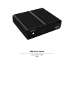
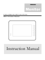
IHD-7310: Indoor Monitor
Instruction Manual
IC REALTIME SECURITY SOLUTIONS
IH-7310 Intercom Monitor Instruction
Manual
IC Realtime
3050 N Andrews Ave Ext
Pompano Beach, FL 33064
Phone 954.772.5327 • Fax 866.860.3860
Table of Contents
1. Features and Specifications ....................................................................... 1
a. Overview .......................................................................................... 1
b. Features ............................................................................................ 1
c. Specifications ................................................................................... 2
d. Dimensions ...................................................................................... 3
2. Monitor Installation ................................................................................... 4
a. General Overview ........................................................................... 4
b. Step by Step Guide ........................................................................ 5
c. Connections..................................................................................... 6
3. Local Screen Operation ............................................................................. 7
a. Main Interface ................................................................................. 7
b. Network Connection ...................................................................... 8
c. Pairing with Outdoor IP Camera.................................................. 9
4. Appendices ................................................................................................ 12
a. Toxic or Hazardous Elements .................................................... 12
I C
R E A L T I M E
S E C U R I T Y
1
Chapter
S O L U T I O N S
Features and Specifications
This section outlines the primary features of the ICRealtime IH-7310 Intercom Monitor.
It also outlines basic Architectural and Engineering specifications.
1.a Overview
T
his IC Realtime series product is design to work together with our other Intercom solution devices.
The monitor incorporates a fully touch enabled screen for easy operation. It adopts an embedded
Linux operating system to maintain reliable, 24/7 operation. Utilizing both H.264 video compression
and G.711 audio compression technology enables the highest quality of streaming audio/video, while
maintaining the lowest bitrate utilization.
The IH-7310 is a monitor with an integrated microphone designed to be incorporated with one of our
Intercom style IP cameras. This monitor is fully suited for full operation as part of ICRealtime's Intercom
solution.
The 800x480 screen resolution and simple to use touch sensitive screen is well equipped for installation in
various institutions ranging from residential, commercial, governmental, and enterprise environments.
1.b Features
IC Realtime IH-7310 series Intercom monitor all support the following features:
Real-time Monitoring
Full 800x480 resolution streaming video at a full 30 FPS.
Record Local Streams / Review Messages
The IH-7310 enables you to record video and take snapshots of your conversation with the person(s) who
started the communication through the intercom IP camera. Review missed calls and listen to messages they
left.
1
I C
R E A L T I M E
S E C U R I T Y
S O L U T I O N S
Compression Format
H.264 video and G.711 audio enables high quality video streaming while maintaining the lowest file sizes
possible for smoother monitoring
Local Operation
Full system control is available at the monitor itself. No need to access over the network as well configurations
can be made at the unit itself.
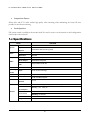
1.c Specifications
Model
Main Processor
System
Operation
System
Video
Audio
Built-in microcontroller
Embedded LINUX operating system
compression
H.264
Resolution
800*480
Audio Input
All-direction microphone
Audio Output
Embedded loudspeaker
Bidirectional
Talk
Display
VTH1560B
Support bidirectional talk
Size
Color 7-inch TFT LCD
input
Touch screen technology
Alarm
Alarm input
Support 8 channels input
Network
Ethernet
10 M / 100 Mbps adaptive
Operating
modes
network
protocol
Power
Power
TCP/IP
DC 10~15V or supply directly by Special switching power
Standby ≤1.5W,work≤7W
Consumption
General
work
Temperature: -10℃~+60℃
environment
Humidity: 10~90%RH
Dimensions
221.2mm×154.3mm×24.2mm(L*W*T);
Weight
0.8Kg;
2
I C
R E A L T I M E
S E C U R I T Y
S O L U T I O N S
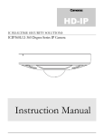
1.d Dimensions
3
I C
R E A L T I M E
S E C U R I T Y
2
Chapter
S O L U T I O N S
Monitor Installation
This section outlines the proper way to mount and install an IH-7310 series intercom
monitor. The suitable method of installing the monitor is limited to Wall installations only.
Note that hardware including screws and anchors are included for the camera installation.
2.a General Overview
4
I C
R E A L T I M E
S E C U R I T Y
S O L U T I O N S
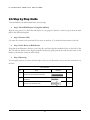
2.b Step by Step Guide
Note: Reference the labeled table below for screw type
Step 1: Install Wall Bracket to Gang Box (86 Box)
Begin by using screw 'a' to fasten the wall bracket to your gang box (86 box). Assure a snug fit from the back
plate to the wall and Gang Box.
Step 2: Fasten to Wall
Use screw 'b' to fasten to the actual wall. If you need, use anchors ('c') to fasten the screws better to the wall.
Step 3: Latch Device to Wall Bracket
Now that the wall bracket is fasten to your Gang Box and wall, align the installation holes on the back of the
IH-7310 with the bracket. Once aligned, pushed forward then gently push down until the clips settle on the
latches on the bracket. Assure the unit is sturdy.
Step 4: Removing
You can gently push up to release the latch clips so that you can then make your power/data connections on
the back.
Screw Illustration
No.
Name
Illustration
Quantit
y
a
M4×30 Cross recessed pan head screws
2
b
ST3×18 Cross recessed pan head tapping screws
- white alloy
2
c
Expansion pipe ¢6*30mm white
2
5
I C
R E A L T I M E
S E C U R I T Y
S O L U T I O N S
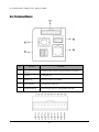
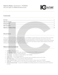
2.c Connections
No.
1
Port Name
Alarm Port
Description
Tie in alarm triggers to this port. See picture below for connections
2
Test Port
For debugging only
3
Network Port
RJ45 port to connect to your network
4
Power Terminal
To power the unit. 12VDC only!
5
Analog/Handset Port
Used for analog systems only. Not applicable to this model
6
I C
R E A L T I M E
S E C U R I T Y
3
Chapter
S O L U T I O N S
Local Screen Operation
This section outlines how to assign an IP address to the monitor and to navigate through the
touch controlled screen
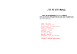
3.a Main Interface
Note: This device does not have a Web Interface and all configuration can be done at the monitor itself.
This section will briefly go over the main interface and action buttons.
7
I C
R E A L T I M E
No.
S E C U R I T Y
S O L U T I O N S
Name
Description
1
Power Indicator
Illuminates when unit is receiving proper power
2
Info Indicator
Illuminates when unit has a new message or new information that has not been looked at
3
S.O.S
Attempts to call the management center where all Intercom devices are managed. !
Requires software to monitor
4
Main Menu
Takes you back to the main menu home page
5
Call Center
Takes you to the call center where you can place a call to other monitors, view
missed/placed calls, monitor live cameras that are attached to the device, and more.
6
Monitor
View live streams from the cameras that are attached to the device
7
Unlock
Press this button during incoming call, calling, and monitoring, you can unlock corresponding
door station
3.b Network Connection
Note: Please use the following default passwords access menus: 002236 or 123456
Step 1: Ensure the monitor is physically connected to your Network, and Powered ON.
Patch the monitor into your network with a standard Ethernet cable. Provide the monitor with power via
12VDC power input jack.
Step 2: Assign an IP address to the monitor.
The IH-7310 Series monitor (and all ICRealtime Intercom based monitors) have a factory default static IP
address of 10.22.15.180. You can change this by navigating to the 'Net Set' menu of the unit. Tap on 'Settings'
'Project Settings' 'Net Set'. Make sure the IP address you are applying conforms to the networks address
scheme. You can also use 'DHCP' to automatically obtain a IP address from the network's DHCP server.
Step 3: DHCP
While still in the 'Net Set' section of the unit choose 'DHCP' and tap 'Ok'. It should grab an available IP address
if there is a DCHP server on the network. We would advise to use a static address once you find an open IP on
the network. Thus you will always know what the IP is of the unit and it will never change.
Note: DHCP addresses have lease times to them. You may obtain a new address when that lease time runs
out or it may stay the same. It is always good to set a static IP to assure it will not change.
8
I C
R E A L T I M E
S E C U R I T Y
S O L U T I O N S
3.c Pairing with Outdoor IP Camera
Note: This section mainly references how to sync our Intercom outdoor IP cameras such as the IHC-6260
with a indoor monitor to complete a intercom setup. Note that this will reference your indoor monitor setup.
Be sure the monitor is online and ready to be used on the network. Please reference our other guides for a
complete setup. http://www.icrealtime.com/forum(click on how-to notes and then 'Access Control')
First start with accessing the outdoor IP camera (IHC-6260) as followed by its manual. You should be
greeted by a screen like below.
Click on the menu option of 'Indoor Station Manager'. This is where you will be adding your indoor
monitor so they are paired to each other. If you see a 'demo' monitor already added, click the icon
under 'delete' to rid of it.
Next, click on the 'add' button at the bottom of the table. Add in a name for the family/location you
are installing for (this is simply for organizational purposes). Add the short number of the indoor
monitor (see indoor monitor walkthrough for more detail). Finally, add the IP address of the indoor
monitor.
9
I C
R E A L T I M E
S E C U R I T Y
S O L U T I O N S
You should now see the added indoor monitor information on the table. You will now need to access
the indoor monitor to add the IP address of this camera so to complete the pairing.
10
I C
R E A L T I M E
S E C U R I T Y
S O L U T I O N S
Navigate on the IH-7310 to 'Settings' 'Project Settings' 'Network'. Here you will input the IP
address of the outdoor camera (IHC-6260). Tap the 'enable' option to turn that camera to being active.
You should now be able to make a call from the outdoor IP camera to the monitor
11
I C
R E A L T I M E
S E C U R I T Y
4
Chapter
S O L U T I O N S
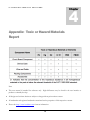
Appendix: Toxic or Hazard Materials
Report
Note
This user manual is intended for reference only. Slight differences may be found in the user interface as
products continually develop.
All designs and software herein are subject to change without prior written consent.
All trademarks and registered trademarks mentioned are the properties of their respective oweners.
Please visit http://www.icrealtime.com for more information.
12