1
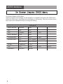
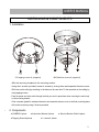
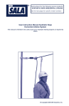
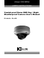
I-Sniper OSD MENU
USER'S INSTRUCTIONS
Vandal-proof Dome DNR Day / Night
Weatherproof Camera User’s Manual
Products : EL-470
USER’S MANUAL
CAUTION
CAUTION
CAUTION
RISK OF ELECTRIC SHOCK
DO NOT OPEN
RISK OF ELECTRIC SHOCK
RISK OF
DOELECTRIC
NOT OPENSHOCKCAUTION:TO REDUCE THE RISK OF ELECTRIC SHOCK
DO NOT OPEN
DO NOT REMOVE COVER(OR BACK).
CAUTION:TO REDUCE THE RISK OF ELECTRIC SHOCK
USER-SERVICEABLE PARTS INSIDE.
CAUTION:TO REDUCE THE RISK OF ELECTRIC NO
SHOCK
DO NOT REMOVE COVER(OR BACK).
DO NOT REMOVE COVER(ORREFER
BACK).SERVICING TO QUALIFIED SERVICE PERSONNEL.
NO USER-SERVICEABLE PARTS INSIDE.
NO USER-SERVICEABLE PARTS INSIDE.
REFER SERVICING TO QUALIFIED SERVICE PERSONNEL.
REFER SERVICING TO QUALIFIED SERVICE PERSONNEL.
ISO14001
ISO14001
ISO14001
The lightning flash with an arrowhead symbol, within an equilateral
triangle is intended to alert the user to the presence of uninsulated
dangerous voltage within the product's enclosure that may be of
sufficient magnitude to constitute a risk of electric shock to persons.
The exclamation point within an equilateral triangle is intended to alert
the user to the presence of important operating and maintenance
(servicing) instructions in the literature accompanying the appliance.
INFORMATION - This equipment has been tested and found to comply with
limits for a Class A digital device, pursuant to part 15 of the FCC Rules & CE Rules.
These limits are designed to provide reasonable protection against harmful
interference when the equipment is operated in a commercial environment.
This equipment generates, uses, and can radiate radio frequency energy and, if
not installed and used in accordance with the instruction manual, may cause
harmful interference to radio communications.
Operation of this equipment in a residential area is likely to cause harmful
interference in which case the user will be required to correct the interference at
his own expense.
WARNING - Changes or modifications not expressly approved by the
manufacturer could void the user’s authority to operate the equipment.
CAUTION : To prevent electric shock and risk of fire hazards:
☞Do NOT use power sources other than those specified.
☞Do NOT expose this appliance to rain or moisture.
This installation should be made by a qualified service person and
should conform to all local codes.
2
USER’S MANUAL
Contents
◑ On Screen Display (OSD) Menu
4
◑ Installing & Components
5
◑ Dimension & Specification
6
◑ OSD Control Button
7
◑ Camera Menu Set Up
1. WDR Control
8
2. BLC
8
3. AGC
9
4. White Balance
10
5. Fluorescent
11
6. ICR DVR TOOL
11
7. RS-485
12
8. Flip
13
◑ Trouble Shooting
14
3
USER’S MANUAL
On Screen Display (OSD) Menu
Camera functions and settings can be adjusted or changed by activating the OSD menu.
When the OSD menu is activated text will display on the monitor. The user can then move
the cursor to the desired function to change the setting.
Setup Menu
WDR CONTROL
MEDIUM
HIGH
BLC
ON
OFF
AGC
NORMAL
HIGH
WHITE BALANCE
ATW
AWB
FLUORESCENT
OFF
CRR
CRR2
ICR DVR TOOL
OFF
ELITE SERIES
FLEX SERIES
MAX SERIES
EDGE SERIES
RS-485
CAMERA #
1~255
FLIP
OFF
HORIZ
SAVE&EXIT
DEFAULT
CANCEL
LOW
VERT
BOTH
USER’S MANUAL
INSTALLING & COMPONENTS
1. Installation
Ø5t apping screw x4 (supplied)
M4 Machine screw x4 (supplied)
- Affix the mounting template to the mounting surface
- Using the L-wrench provided, loosen 4 screws by turning them and separate the dome cover
- Drill holes on the celling by matching to the holes on the case bed. Fix the case bed on the ceilling by
using tapping screws.
- Pass the power and video cable through the hole you want to pass them when mounting the main body
on the mounting bracket.
- Point a camera gimball to a desired derection and assemble a dome cover to the flush mounting base
with socket screws by using L-Wrench provided.
2. Components
● CAMERA 1piece
● Instruction Manual 1piece
● Tapping Screw 4pieces
● Service Monitor Cable 1piece
● L-wrench 1piece
5
USER’S MANUAL
DIMENSION & SPECIFICATION
1. Dimension & Connection
Dimension
Connection
2. Specification
MODEL
Image Sensor
Effective Pixels
Synchronization
Scanning System
Horizontal Resolution
Min. Illumination
S / N (Ratio)
Video Output
Camera Title
Backlight Compensation
WDR
Activity Zones
Privacy Masking
DNR
Sens - up (Slow Shutter)
AGC
White Balance
Color Temperature
Electronic Shutter Speed
Digital Zoom
Power
Power Consumption
Lens
Operating Temperature/Humidity
Storage Temperature/Humidity
Dimension
Weight
6
IR LED VANDAL DOME
PIXIM 1/3” High Sensitivity Digital Sensor
768(H) x 540(V)
Internal
2:1 Interlace / Progressive selectable
700TVL Effective
0.1Lux/50IRE/F1.2(Color), 0.01 Lux/50IRE(B/W)(Sens-Up*64x)
More than 50dB @50Lux
CVBS x2(75Ω), UTP, ITU656(Digital)
Available
ON / OFF
LOW / NORMAL / MEDIUM / HIGH(Max. 120dB)
4 Programmable Zones
12 Programmable Zones
AUTO
Selectable x2~x64
LOW / MEDIUM / HIGH
ATW / AWB
2,000~11,000°K
1/25-1/30,720 SEC@(F1.2)
~ x4, Pan / Tilt
DC 12V
IR LED ON:700mA Max
DC Auto Iris Varifocal Lens(2.8mm-12mm)
-10 ~ +50 Deg C. RH 95% Max.
-20 ~ +60 Deg C. RH 95% Max.
146mm(W) * 105mm(H) * 146mm(D)
1400g
USER’S MANUAL
OSD Control Button
1. OSD button could be used when it needs to OSD control.
▲ Up button: Moves the cursor upwards. Use this button to select an item
or adjust the parameters.
▼ Down button: Moves the cursor downwards. Use this button to select an
item or adjust the parameters.
◀ Left button: Moves the cursor to the left. Use this button to select or
adjust the parameters of the selected item. The parameter changes
each time this button is pressed.
▶ Right button: Moves the cursor to the right. Use this button to select or
adjust the parameters of the selected item. The parameter changes each
time this button is pressed.
◎ Set button: Executes selections and displays a submenu for an item with
the
mark.
7
USER’S MANUAL
WDR Control
WDR gives the camera the ability to capture shadow and highlight detail at the same time
without artifacts. It is measured by " deep black" and crisp white while retaining image
detail. It is also measured by subtlety of gradations.
1. When the OSD menu screen is displayed, highlight 'WDR CONTROL' by using the
Up and Down buttons.
ICREALTIME
WDR CONTROL
BLC
AGC
WHITE BALANCE
FLUORESCENT
ICR DVR TOOL
RS-485..
FILP
SAVE&EXIT DEFAULT
HIGH
OFF
NORMAL
ATW
OFF
OFF
OFF
CANCEL
2. Press the right button to choose from the following options.
- MEDIUM
- HIGH
BLC(Back-Light Compensation)
Enables a user to select a desired area on a picture and view that area more clearly.
ICREALTIME
WDR CONTROL
BLC
AGC
WHITE BALANCE
FLUORESCENT
ICR DVR TOOL
RS-485..
FILP
SAVE&EXIT DEFAULT
HIGH
OFF
NORMAL
ATW
OFF
OFF
OFF
CANCEL
USER’S MANUAL
BLC OFF
BLC ON
- OFF : Select this when you back-light conditions are not a concern.
- ON : Select this when back-light conditions interfere with proper illumination of the
foreground subject. Enter the selection to adjust percent BLC illumination correction.
AGC(Auto Gain Control)
Automatically adjust brightness according to the incoming signal. The higher the AGC-the
brighter the screen, but also the higher the noise.
ICREALTIME
WDR CONTROL
BLC
AGC
WHITE BALANCE
FLUORESCENT
ICR DVR TOOL
RS-485..
FILP
SAVE&EXIT DEFAULT
HIGH
OFF
NORMAL
ATW
OFF
OFF
OFF
CANCEL
- NORMAL : Select this default setting when you want a moderate level of brightness
compensation by AGC.
- HIGH : Select this when you may want increased brightness levels to be compensated
by AGC.
- LOW : Select this when you may want less brightness compensated by AGC.
9
USER’S MANUAL
White Balance
White Balance is a function which compensates different colors of light being emitted
from different light sources. Users can select the appropriate levels according to the
environment.
1. When the OSD menu is displayed, highlight 'WHITE BALANCE' by using the Up and
Down buttons.
ICREALTIME
WDR CONTROL
BLC
AGC
WHITE BALANCE
FLUORESCENT
ICR DVR TOOL
RS-485..
FILP
SAVE&EXIT DEFAULT
HIGH
OFF
NORMAL
ATW
OFF
OFF
OFF
CANCEL
2. Use the right / left buttons to change a menu option. Press SETUP to enter a sub-menu
item.
- ATW : The ATW mode continuously monitors color
temperature. Color temperature and white balance can be automatically adjusted
accordingly. The levels of the color temperature setting are adjustable between 2,000˚K
and 11,000˚K(i.e. fluorescent light, outdoor, sodium vapor lamp, etc).
- AWB : "One touch" white balance which is set with a white card and is locked to that
white balance setting regardless of scene content.
10
USER’S MANUAL
Fluorescent
1. When the OSD menu is displayed, highlight 'FLUORESCENT' by using the Up and
Down buttons.
ICREALTIME
WDR CONTROL
BLC
AGC
WHITE BALANCE
FLUORESCENT
ICR DVR TOOL
RS-485..
FILP
SAVE&EXIT DEFAULT
HIGH
OFF
NORMAL
ATW
OFF
OFF
OFF
CANCEL
2. Use the right / left buttons to change a menu option.
- OFF : No fluorescent lighting compensation.
- CRR : With 12vdc, eliminates most color rolling and preserves dynamic range capture
mode.
- CRR2 : Eliminates a broader range of color rolling conditions vs. CRR setting.
ICR DVR Tool
1. If you select "OFF", Sharpness goes up. Generally, Sharpness goes down at normal and
low light condition and the image at low light condition is bright. You can decide the mode
of sharpness by switching and reviewing each mode.
ICREALTIME
WDR CONTROL
BLC
AGC
WHITE BALANCE
FLUORESCENT
ICR DVR TOOL
RS-485..
FILP
SAVE&EXIT DEFAULT
HIGH
OFF
NORMAL
ATW
OFF
OFF
OFF
CANCEL
USER’S MANUAL
2. Use the right / left buttons to change a menu option.
- OFF
- ELITE SERIES
- FLEX SERIES
- MAX SERIES
- EDGE SERIES
RS-485
RS-485 is a function which set up camera #, protocol and baud rate.
ICREALTIME
WDR CONTROL
BLC
AGC
WHITE BALANCE
FLUORESCENT
ICR DVR TOOL
RS-485..
FILP
SAVE&EXIT DEFAULT
HIGH
OFF
NORMAL
ATW
OFF
OFF
OFF
CANCEL
RS485 SETUP
CAMERA # :
PROTOCOL
BAUD RATE
RETURN.
- CAMERA # : 1~255
- PROTOCOL : PELCO-D
- BAUD RATE : 9,600bps(2,400~19,200)
12
1 < 1 > 255
PELCO-O
9600
USER’S MANUAL
Flip
Changes the direction of the camera image displayed on the screen.
- VERTICAL
- HORIZNTAL
- BOTH
- OFF
ICREALTIME
WDR CONTROL
BLC
AGC
WHITE BALANCE
FLUORESCENT
ICR DVR TOOL
RS-485..
FILP
SAVE&EXIT DEFAULT
HIGH
OFF
NORMAL
ATW
OFF
OFF
OFF
CANCEL
13
USER’S MANUAL
●
Nothing appears on
the screen.
☞Check the power cable, power supply output and video
connection between the camera and monitor.
☞Are the camera lens or the lens glass dirty?
The image on the
screen is dim.
Clean the lens / glass with a soft clean cloth.
☞Adjust the monitor controls, as required.
☞If the camera is facing a very strong light, change
the camera position.
☞Adjust the lens focus.
The image on the
screen is dark.
☞Adjust the contrast control of the monitor.
The camera is not
working properly
and the surface of
the camera is hot.
☞Check the camera is correctly connected to an appropriate
Motion Detection
is not activated.
☞Has MOTION DET been set to ON in the menu?
The color of the
picture is not correct.
☞If there is an intermediate device, correctly set the 75Ω/Hi-z.
regulated power source.
☞Has MD AREA been properly defined?
☞Check the settings in WHITE BALANCE menu.
The image on the
screen flickers.
☞Make sure that the camera isn’t facing direct sunlight or
The SENS-UP does
not work.
☞Check that the AGC setting in the EXPOSURE menu is’t set to OFF.
fluorescent lighting. If necessary,change the camera position.
☞Check the EXPOSURE menu and make sure SHUTTER is set to------.
USER’S MANUAL
15
WWW.ICREALTIME.COM