1
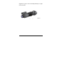
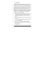
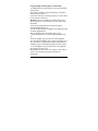
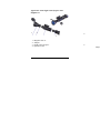
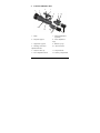
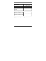
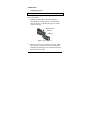
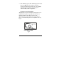
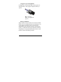
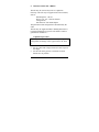
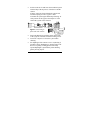
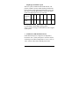
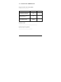
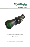
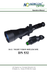
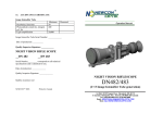
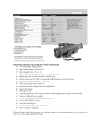
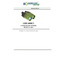
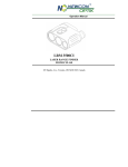
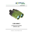
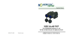
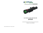
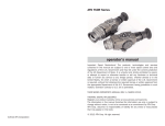
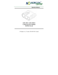
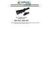
Operation Manual DAY / NIGHT VISION RIFLESCOPE DN 532 / DN 533 105 Sparks Ave., Toronto, ON M2H 2S5, Canada IMPORTANT INFORMATION Read prior to activation. DN 532/DN 533 is a sophisticated electronic device. To operate it properly, please read this manual carefully. Ignoring operation procedures described in this manual will void your warranty. NEVER disassemble the unit. This device contains a source of high voltage, which may be hazardous to your health. NEVER open objective lens of an active unit in bright light, including daylight. In the daytime objective lens must be covered by caps. A tiny hole in each cap provides enough light for daytime testing. NEVER aim active unit at intense light sources, such as lights, headlamps, campfires, the Moon, etc. NEVER reverse the polarity of a battery. NEVER connect the unit to external power sources. ALWAYS remove battery when not in use for a long period. ALWAYS keep the objective lenses covered when not in use. ALWAYS store in a warm dry place. Precautions DN 532/DN 533 is a sophisticated precise optical instrument equipped with electronics. It should be handled with due care: Unit contains fragile components. Avoid impacts, dust, moisture and sharp changes of temperature. Do not touch the optical surfaces other than for cleaning. Doing so may damage the anti-reflection coating. Clean optical surfaces with professional lens cleaning supplies. Use only a soft clean cloth to clean the exterior of the device. Keep away from sources of heat, such as heating appliances, sunlight or central heating. Switch off the unit and remove the battery during the extended periods of non-operation. Do not keep the device at temperatures higher than 60oC (140oF). Do not apply excessive force or pressure to the lens assembly, movable parts and thread connections. Small dark and/or light points may be seen in the field of view due to considerable optical magnification of the eyepiece. This does not affect the operational capabilities of the device. CONTENTS 1. BRIEF DESCRIPTION 1.1 Overview 1.2 Key Features 2. UNIT EXTERIOR VIEW 3. DELIVERY SET 3.1 Standard delivery set 3.2 Optional accessories: 4. SPECIFICATIONS 5. OPERATION 5.1 Changing eyepieces 5.2 Using the scope in the daytime 5.3 Using the scope in the nighttime 5.4 Battery installation 5.5 Night time operation 5.6 Switching the unit off 6. INSTALLATION ON A RIFLE 6.1 Adjustment procedure 7. TAKING PHOTOS AND VIDEO SHOOTING 7.1 Attaching Unit to photo/video camera 1 3 3 5 8 9 9 9 10 12 12 13 14 14 15 15 16 16 19 19 7.2 Diaphragm and shutter speed STORAGE AND MAINTENANCE TROUBLESHOOTING 9.1 The scope does turn on 9.2 The target does not appear in focus. 9.3 Image has disappeared. 9.4 Condensation accumulates on the parts 9.5 Black dots on the screen 9.6 Bright spots on the screen 10. WARRANTY 11. CUSTOMER SUPPORT 12. ACCEPTANCE CERTIFICATE 8. 9. 2 21 21 22 22 22 22 23 23 23 24 26 27 1. BRIEF DESCRIPTION Overview DN 532/DN 533 device (the unit) is a universal riflescope, intended for shooting and around the clock observation. The unit has two eyepieces – for day and night observation. The night vision eye piece has an integrated IR illuminator. Powerful high light ratio optics of the daytime part provides 7x or 11x magnification. The night-time eyepiece contains an image Fig 1. Day time configuration Fig 2. Night time configuration intensifier tube, which amplifies light in visible and near infrared spectrum. Unit provides night recognition range of 400-800 m, system magnification 3.7x or 6x times and visual angle 7.4 (7x) or 4.6 (11x) degrees. 3 Night time eyepiece can be used independently as a night time monocular. Fig 3. Night vision eyepiece 4 Key Features All known models of day/night scopes with removable eyepieces use standard optic scheme of a day-vision scope with 11-13 lenses. As a rule, the actual F-number of all system does not exceed 3.0 (sometimes 2.0), which is not enough for the night vision equipment. Also, as common day time scopes have relatively small field of view, in a night mode only small central part of the electronic tube working area is used. A unique 23 lens design provides the unit a 2-2.5 stronger light transmission (F 1.5 with 66 mm aperture), twice wider field of view and entire working area of the photocathode. High resolution 18 mm Image Intensifier Tube and special light-collecting optics provide bright, sharp image of consistent quality from the center to the edges. Powerful IR illuminator (optional) is effective for up to 200 m Unit is equipped with automatic brightness protection Camera/video adaptable Precise internal windage/elevation adjustments Standard weaver mount or optional weaver rail or side rail mounts Long eye relief The scope is water resistant and can be used in rain. 5 Using the Night Vision Eyepiece as monocular As standard the NV monocular gives an inverted (upsidedown) image. To provide a ‘normal’, non-inverted image, you need to attach an optical inverter to the back of the NV’s existing eyepiece (4). This is done by screwing it in clockwise. Warning ! Do not overtighten or misalign the inverter. The NV Eyepiece is now ready for use as a night vision monocular. To increase the magnification of the NV Eyepiece (standard magnification 1x), you can use the optional 3x magnifier lens which provides 3x image magnification. The 3x magnifier lens can be fitted in two ways: - Install the magnifier 3x with the supplied adapter ring (2). Screw the adaptor ring on to the rear of the magnifier lens. Push the lens/adaptor ring over the front of the NV’s lens. This allows a quick push on/pull off magnification capability, but is not designed for long term observation. - Leave the adaptor ring (2) off and screw the magnifier lens directly in to the screw thread inside the front of the NV’s objective lens. This is a more secure assembly designed for long term observation. 6 Appearance of the Night Vision Eyepiece with magnifier 3x 1 2 4 3 1 - Magnifier lens 3x 2 - Adapter 3 - Night Vision Eyepiece 4 - Optical inverter 4 Fully a 7 2. UNIT EXTERIOR VIEW 4 1 5 7 11 6 10 3 12 2 8 1 – Body 9 7 – Infrared illuminator (optional) 8 – Focus adjustment rings 9 – Rubber eye cup 10 – Weaver mount 2 – Daytime eyepiece 3 – Night time eyepiece 4 – Windage / Elevation adjustment knobs 5 – Objective lens cap 6 – Focus adjustment knob 11 – Bayonet knob 12 – Battery compartment 8 3. DELIVERY SET Standard delivery set - Main body - Daytime eyepiece - Night time eyepiece - Rubber eyecup - Objective lens cup - Optical inverter for the night time eyepiece - Rifle mount - User manual - Warranty card - Soft case Optional accessories: - Infrared illuminator - Camera/video adapter (52mm/37mm) - 3x lens for the night time eyepiece - Hard case 9 1 pc. 1 pc. 1 pc. 2 pc. 1 pc. 1 pc. 1 pc. 1 pc. 1 pc. 2 pc. 4. SPECIFICATIONS Optical parameters 7x 11x Objective focus length / F number 100 mm / F1.5 166 mm / F2.0 Magnification (day/night) 7.0x / 3.7x 11.2x / 6.0x Field of view(day/night) 3.7º / 7.4º 2.3º / 4.6º Objective lens diameter 66 mm Eye relief distance 83 mm 60 mm Focusing distance, min 20 m Dioptre adjustment -4…+2 Dimensions 340x82x82 mm Weight (day / night) 0.99 kg / 1.05 kg 1.17 kg / 1.23 kg 440x83x83 mm Electrical parameters (night time eyepiece) CR123 Lithium Battery type Battery life, min 40 hours Image intensifier tube GEN 2+ / GEN 3 Photocathode sensitivity, A/lm >550 / >1200 Light amplification 35,000-45,000 Resolution 45-64 lp/mm 10 Infrared illuminator (optional) 50 mW / 75 mW / 150 mW / 200 mW Emission power Battery type 2 AA or 1 CR123 Illumination angle 5º - 20º Illumination wavelength spectrum 805-830 nm Mechanical parameters ¼ MoA (7.27 mm / 100 m) 120 MoA (±1.75 m / 100 Adjustment mechanism, range m) Adjustment mechanism, step Specifications are subject to change without notice. 11 OPERATION Changing eyepieces Do not apply superfluous force while changing eyepieces! To change day time eyepiece for a night time one and the other way around: 1. Holding the unit firmly in two hands push the bayonet button towards objective (as indicated by arrow on the Fig. 5) and turn the eyepiece counter clockwise till stop. Bayonet knob O sign ◄ sign Fig 5. Changing eyepieces 2. Pull the eyepiece away from the scope body. Slight effort may be required to overcome air depression resulting from opening a water-resistant connection. Pack the eyepiece safely. 12 3. Take another eyepiece and match O sign on the scope body with ◄ sign on the eyepiece. Insert the eyepiece into the bayonet on the unit, press slightly Unit and eyepiece together and turn eyepiece clockwise till you hear a slight click. Using the scope in the daytime With daytime eyepiece attached take the objective cover off. Rotate the eyepiece to get the reticle in focus. To eliminate parallax of the objective lens set the approximate observation range (observation range in metres is indicated) using the focus adjustment knob (6, Fig.4). Focus adjustment knob Fig 6. 13 Using the scope in the nighttime For night time use attach the night vision eyepiece as described above. This eyepiece requires a battery to operate. Fig 7. Installing battery into night time eyepiece Battery installation Night channel of the unit utilizes one CR123A Lithium battery. Prior to installation make sure that battery is in good condition. Install the battery into the battery compartment of the night time eyepiece observing the polarity, as indicated on the body and inside the battery compartment. An optional IR illuminator utilizes 2 AA batteries. Follow the similar procedure 14 Night time operation Take off the objective lens cap. Switch the unit on by turning the switch into position ON. In a few seconds greenish fluorescent glow will become visible through the eyepiece. Rotate the eyepiece focus adjustment ring until you get the reticle in focus. Turn the distance adjustment knob until you get the best image. If you need to illuminate the observed object, install and switch on the optional infrared illuminator. Warning! Do not use night-time eyepiece in the daytime. Do not aim the working night-time eyepiece toward sources of bright light: lamps, welding, etc. – that may cause decrease of the light amplification coefficient. Do not leave the switched on night time eyepiece motionless for more than 30 minutes in semi-bright conditions to avoid photocathode fatigue. Switching the unit off After you have finished using the unit, turn it off by rotating switch to OFF position. Ensure the protective lens cap is on the lens. Remove batteries from the battery compartment to avoid damage of the device in case of electrolyte leakage. 15 5. INSTALLATION ON A RIFLE The unit may be used as a day time or a night time riflescope. The unit may be supplied with various mounts, such as: Standard prism – SP 532 Weaver 7/8’’ rail – WP 532 (default configuration) Side mount or side mount adapter. The particular mount configuration is determined by the order. The unit may be supplied without a binding attached to it to enable installation on a specific rifle model. Contact a gunsmith for installation. Adjustment procedure Scope adjustment is necessary for either day or night time configuration. Exchange of the eyepieces does not affect it. Attach the unit to the rifle. Set up a panel with a target at 100 m. Focus scope on the target. Set the rifle on the gun rest to eliminate as much human error as possible. 16 Making certain the rifle is empty with no cartridge in the chamber and the breech is open install mechanical or laser bore sighter. Install laser bore sighter in the muzzle of your rifle lining it up with the scope as close as possible. Looking through the scope as though you were going to shoot you should see reticle produced by the unit and a cross hair produced by the bore sighter. They should line up with each other vertically, horizontally and be in complete alignment. If they are not parallel with each other, adjust the bore sighter in the chamber. Unscrew the protective caps of the reticle adjustment screws. Turning those screws match reticle crosshairs with the aimed point, provided by the mechanical sight or laser bore sighter. Remove the bore sighter from the muzzle. Make 2-3 shots. Having examined the target, make necessary corrections. For example, in order to move the hit point downwards and leftwards, adjustment screw should be turned counter clockwise, in the Down and Left directions. The aiming point will move upwards and rightwards correspondingly. If you are not hitting the paper target at all, move the target closer until you consistently hit somewhere on the target. You cannot make any scope adjustments if 17 you do not know which direction to make it. Do not be concerned if you did not hit the bull’s eye. Once you initially hit the target sheet you can make adjustments and then gradually move the target back out to the 100 yard mark. When the desired precision is achieved set the protective caps into their places. The unit is now ready for operation. Both sight adjustment knobs are equipped with the precise click mechanism, where 1 click is equal to 1/4 MoA (Minute of Angle). One click adjusts the sight reticle to 1.5 cm at 100 meter target up to 1.75 meter maximum (120 MoA). 18 6. TAKING PHOTOS AND VIDEO SHOOTING Unit can be supplied with an optional adapter for photo/video cameras for night photo/video shooting. Night photo shooting can be performed by 35mm SLR cameras, with standard objective lens (50-58 mm focus), such as Nikon, Canon, Pentax. Attaching Unit to photo/video camera Screw the supplied adapter ring (52 mm or 37 mm diameter) in the objective lens of your camera. If the objective lens of your camera has another diameter for a light filter (for example, 49mm or 58mm) use step-up or step-down adapter rings from the 52 mm to your size. Such adapters are not supplied by Newcon; they are generally available through camera stores. Remove the eye cup from the unit. Set the eyepiece in the middle position. Screw the adapter ring attached to camera into internal eyepiece thread. 19 Switch on the device and focus the assembled system with the help of the objectives of the device and the camera. If image cannot be focused detach the camera and turn the coupling of Unit’s eyepiece a little. Assemble the system again and attempt focusing. At some position of the eyepiece and objective of the camera the system will be focused. Figure 6. Connecting to photo and video camera VIDEO Fasten the adapter ring with the camera to the body of the eyepiece of the unit with three locking screws. Turn Unit’s objective to focus the system while shooting. Set diaphragm of the camera to 2.8 or 4 (shooting is possible at lower diaphragm too, but the images will have lower quality). Taking photos with a fully opened diaphragm is justified only when shooting quickly moving objects. 20 Diaphragm and shutter speed The TTL system, installed at most SLR cameras, will properly estimate exposure while shooting with the unit. If your camera is not equipped with the TTL system, the table below will help approximately estimate the shutter speed at the diaphragm of 2.0 for your film: Film 50 100 200 400 800 1600 3200 sensitivity (ISO) Shutter 1 1/2 1/4 1/8 1/15 1/30 1/60 speed, sec. Use ISO 400 film or higher. Usage of a tripod is strongly recommended to obtain higher quality photos. Using a tripod is strongly recommended to achieve higher quality photos. 7. STORAGE AND MAINTENANCE If Unit has been kept for a long time at temperatures lower than -40C (-40F), then prior to use the it must be warmed up at an ambient temperature of -10C (14F) to +40C (104F) with relative humidity below 80%. 21 8. TROUBLESHOOTING The scope does turn on Check that the batteries are installed properly. Check the charge of the batteries. Replace if they are weak. Do not mix old batteries with new ones. The target does not appear in focus. Bring the target to the center of the image. Turning the knob (6, Fig. 4) and focus adjustment rings (8, Fig. 4) eyepiece achieve the clearest target acquisition on the screen. If the image still does not seem to be in focus, clean the lenses. They could be foggy or dusty. Image has disappeared. If the objective lens of switched on the unit are exposed to bright light it automatically shuts off to protect the image intensifier tube from overload. When this happens, turn the unit off, wait for a few seconds and turn it on again. If the image has been lost at the moment of a shot, check contacts in the battery compartment. 22 Condensation accumulates on the parts In order to avoid misting of the eyepiece lens at cold temperature use a special protective cover. Black dots on the screen These are the blemishes in the image intensifier, which do not affect the performance or reliability of a night vision device. Blemishes may vary in size and number; those are inherent in the manufacturing process. Most of them are seen in the daytime only and become almost invisible during the night time. Bright spots on the screen The image may contain some bright spots caused by gradual relief of static electricity from the cathode. This feature may appear immediately after assembling of the device or attaching/detaching of the objective lens, and it always disappears within 5-14 days of usage or storage. 23 9. WARRANTY NEWCON warrants this product against defects in material and workmanship for one year from the date of the original purchase. Longer warranty is available, subject to the terms of the specific sales contract. Should your Newcon product prove to be defective during this period, please deliver the product securely packaged in its original container or an equivalent, along with the proof of the original purchase date, to your Newcon Dealer. Newcon will repair (or at its option replace with the same or comparable model), the product or part thereof, which, on inspection by Newcon, is found to be defective in materials or workmanship. What This Warranty Does Not Cover: NEWCON is not responsible for warranty service should the product fail as a result of improper maintenance, misuse, abuse, improper installation, neglect, damage caused by disasters such as fire, flooding, lightning, improper power supply, or service other than by a NEWCON Authorized Service. 24 Postage, insurance, and shipping costs incurred while presenting your NEWCON product for warranty service are your responsibility. If shipping from North America please include a cheque or money order payable to NEWCON OPTIK for the amount of $15.00 to cover handling and return shipping. 25 10. CUSTOMER SUPPORT Should you experience any difficulties with your NEWCON OPTIK product, consult the enclosed manual. If the problem remains unresolved, contact our customer support department at (416) 663-6963 or toll free at 1877-368-6666. Our operating hours are 9am-5pm, Monday - Friday, Eastern Standard Time. At no time should equipment be sent back to Newcon without following the instructions of our technical support department. NEWCON OPTIK accepts no responsibility for unauthorized returns. To locate NEWCON Authorized Dealer call: Tel: (416) 663-6963 Fax: (416) 663-9065 Email: [email protected] Web: www.newcon-optik.com The defective products should be shipped to: US Customers: 2498 Superior Ave. Cleveland, OH 44114 From all other countries: 105 Sparks Ave., Toronto, ON M2H 2S5, CANADA 26 11. ACCEPTANCE CERTIFICATE Image intensifier tube serial number: ____________________ Minimum Resolution, lines/mm 45 Photocathode sensitivity, integral, A/lm 550 Light amplification 30,000 Production date: _____________________________________ Quality Inspector signature: ___________________________ 27 Measured NIGHT VISION RIFLE SCOPE DN Magnification: 532 533 7x 1x Riflescope serial number: _________________________________________ Night vision eyepiece serial number: _________________________________ The unit meets all technical specifications and has passed the quality assurance inspection. Production date: ___________________________________ Quality Inspector: __________________________________ Quality Assurance Seal 28 R1 – 5.11 NEWCON OPTIK Printed in Canada