1
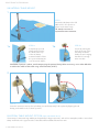
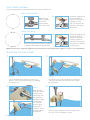
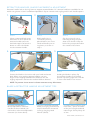
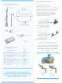
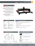
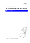
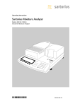
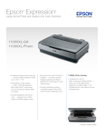
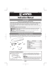
Hinged
Ring Frame
User Manual
Uncompromised Exposure
RING FRAME USER MANUAL
UNILATERAL TABLE MOUNT
1.
STEP 1
Secure the rail clamp to the OR
table rail 10 - 20" superior or
inferior to the incision site.
10-20"
1a.
TIP: Attach near area of
expected heaviest retraction.
1b.
STEP 1a
Completely open rail
clamp jaw by turning
the knob at the top
of the rail clamp
counterclockwise. Place
the open rail clamp jaw
over the sterile drapes.
STEP 1b
Secure by turning the
knob at the top of the
rail clamp clockwise.
Utilize the two hanging
handles for leverage
when needed.
CAUTION: If patient is obese, avoid compressing the patient’s body. When necessary, use a wider OR table
or add to the width of the table using a Rail Extender (41917).
2.
STEP 2
Insert the extension arm into the rail clamp joint and temporarily lock in place by flipping the rail
clamp joint handle to the “locked” position.
BILATERAL TABLE MOUNT OPTION
[NOT INCLUDED IN KIT]
If necessary, for increased ring stability and especially for larger exposures, such as liver transplant, utilize a second rail
clamp mounted on the opposite side of the table with an additional extension arm.
2 RING FRAME USER MANUAL
RING FRAME ASSEMBLY
Select the appropriate sized ring frame based on the procedure size.
SMALL, CIRCULAR RING:
a.
Mate the ring
halves together
so that the
serrated faces
meet each other.
b.
Rotate the 2 tightening
screws clockwise to
secure the ring halves
together on each
side. The ring may be
secured in a hinged or
flat position.
b.
Rotate the 4 tightening
screws clockwise to
secure the ring halves
and ring extensions
together. The ring may
be secured in a hinged
or flat position.
LARGE, OVAL RING:
a.
Mate the ring halves and extensions together
so that the serrated faces meet each other.
NOTE: Screw must be completely tightened and serrated faces must be fully seated together to ensure a secure attachment.
MOUNTING THE RING FRAME
1.
2.
2"
STEP 1
STEP 2
Use an assistant (if needed) to position ring
frame 2" above the patient’s body, surrounding
the incision site.
Unlock the joint on the rail clamp to release the
extension arm and slide extension arm toward
the ring frame.
3.
STEP 3
Wrap the latch
joint jaws around
the ring frame
(shown top left)
and secure by
flipping the latch
joint handle to
the “locked”
position while
grasping the
extension arm for
leverage (shown
bottom left).
3 RING FRAME USER MANUAL
4.
STEP 4
Once ring and extension arm are in place, lock
the joint on the rail clamp to secure.
RETRACTOR HANDLES, BLADE PLACEMENT & ADJUSTMENT
Retractor handles lock to the ring frame to support retractor blades. 10" retractor handles are available for use
with the ring frame in Cam II and Micro-Adjustable II Clip-on varieties with angling and S-Lock® handle options.
1.
2.
3.
press
STEP 1
STEP 2
STEP 3
Select a retractor blade, press
the button on the head of the
retractor handle and insert
the blade nipple. Release the
button to secure the blade
into the retractor handle.
With handle joint in
“unlocked” position,
place blade in site. Place
unlocked handle joint on
ring frame, as shown in
step 3.
Clip the joint to the ring
frame by pushing the joint
down over the bar. Keep the
bulk of the joint positioned on
the outside of the frame.
4.
5.
STEP 4
STEP 5
Position the blade in the incision with your hand and retract
back. When using angling retractor handles, use your
fingers or the Angling Head Wrench (43032) to turn the
angling adjustment and tow the retractor blade as desired.
Holding the blade in place, flip
the retractor handle to the locked
position squeezing against the handle
to secure the blade in the incision.
NOTE: To prevent tissue necrosis release retractors every 20 minutes.
BLADE & RETRACTOR HANDLE ADJUSTMENT TIPS
•
To retract a blade after a
Micro-Adjustable II Retractor
Handle has been locked, turn
the knob to utilize microadjustable
retraction (as shown above).
•
To angle a locked & retracted
blade, an angling head wrench
may be desired for increased
leverage. Angling Head
Wrench (43032).
•
To easily remove clip on joints
from Arms, “pinch” the back
of the joint using thumb and
index finger. Gently lift up off
of arm.
RING FRAME USER MANUAL 4
RING FRAME USER MANUAL
Hinged Ring Frame
ACCESSORIES AND
TROUBLESHOOTING
Sterile mount
table attachment
The Thompson Retractor offers exceptional
versatility and can be set up to meet all your
exposure needs. Please use the following
accessories and troubleshooting tips
for easiest set up. If you have additional
questions, please contact your account
manager at 1-800-227-7543.
D
Utilize ring frame halves together
to build a circular frame for small
procedures. Hinge either side
for multi-planed retraction or to
meet patient anatomy.
D
C
A
C
Utilize with the ring frame halves
to extend the ring into an oval
frame for larger procedures.
B
THE RAIL CLAMP IS
INTERFERING WITH
THE PATIENT
If a bigger bed cannot
be used, use our Rail
Extender (41917).
If setting up the frame
bilaterally, two are required.
E
F
H
G
HINGED RING FRAME KIT
QTY
RAIL CLAMP DOES
NOT FIT ON OR TABLE
Call for an extender, or
if using a Jackson Frame
Table, a Jackson Frame
Adapter (41927) is available.
If setting up the frame
bilaterally, two are required.
ITEM DESCRIPTION
PART #
S-Lock Hinged Ring Frame Kit
SL90020
A
1
Elite II Rail Clamp 18"
41902AC
B
1
Extension Arm with Cam Latch Joint 16"
44614LC
C
2
Ring Half Hinged 14 1/2"
44218
D
44220
2
Ring Extension 3"
E
5
Cam II Clip-on Angling 10"
SL42126WAL
F
2
Micro-Adjustable II Clip-on Angling 10"
SL45006CA
G
1
Angling Head Wrench
43032
H
1
Instrument Case 22" x 11" x 3 1/2"
with Pin Mat
50000G
PLEASE REFER TO THE THOMPSON
SURGICAL CLEANING AND STERILIZATION
MANUAL FOR COMPLETE CLEANING AND
STERILIZATION INSTRUCTIONS.
HOW CAN I OBTAIN RETRACTION
PERPENDICULAR TO THE FRAME ARMS?
Our patented Cam II and Micro-Adjustable II
Handles allow the blade to swivel and retract
in any direction as shown. S-Lock blades and
handles help secure blades in any orientation
without unwanted movement.
swivel
to
1 Swivel
align on
tissue
locked
2
Lock in
place when
movement is
not wanted
RING FRAME USER MANUAL 5
Rev B
122214
rfum1214
10170 East Cherry Bend Road
Traverse City, Michigan 49684
phone: 231.922.0177
fax: 231.922.0174
thompsonsurgical.com
EC
REP
Emergo Europe
Molenstraat 15
2513 BH, The Hague
THE NETHERLANDS
0297
© 2014 Thompson Surgical Instruments, Inc. Traverse City, Michigan.
® S-Lock and the T-Circle Logomark are Registered Trademarks of Thompson Surgical Instruments, Inc.
Patents: US4971038, US5025780, US5888197, US5897087, US5902233, US5984865, US6017008, US6033363, US6416465,
US6511423, US7338442, US7749163, US8257255, US8360971, US8617064. Other patents pending.
Made in the USA
For a FREE TRIAL
call 1.800.227.7543
Free trial valid for U.S. customers only.
International customers please call for more information.