1
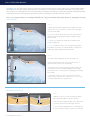
PLA® System
User Manual
Uncompromised Exposure.
PLA SYSTEM USER MANUAL
INTENDED USE: The PLA retractor system is intended for posterior lumbar exposure for procedures such as: Transforaminal Lumbar
Interbody Fusion, Posterior Lumbar Interbody Fusion, Decompression, and Pedicle Screw Fixation applications. The system allows
spine surgeons to accomplish minimal access with maximum visualization, by utilizing a versatile frame platform and providing flexible,
independent retraction and angling from all directions while also allowing for controlled and stable exposure.
Prior to use, inspect all parts for damage: DO NOT use if any part has been deformed, altered, or damaged in any way.
TABLE MOUNT:
STEP 1
A Attach the Elite II Rail Clamp jaw to the table rail 18-24”
away from the site of operation on either side of the table
over the sterile drape.
B
B To secure, turn the knob at the top of the rail clamp and
utilize the attached hanging handles for added leverage
when needed.
18-24"
TIP Position so that the rail clamp will not interfere with
imaging equipment.
CAUTION If patient is obese, avoid compressing patient’s
body. When necessary, use a wider OR table or add to the
width of the table using Rail Extender (41917).
A
STEP 2
A Insert the Articulating Arm into the rail clamp joint.
B Ensure the distal end of the arm can reach the site of
operation with several inches of flexibility.
B
C Rotate the arm out of the working area until ready to be
used and lock to the rail clamp by flipping the rail clamp
joint handle to the “locked” position, grasping the rail clamp
for leverage.
C
A
TIP If a larger range of motion is needed, move the rail
clamp closer to operation site. If arm is too close, move the
rail clamp farther from the operation site.
SEQUENTIAL DILATION:
STEP 3
A After the incision is made, insert the first dilator
and sequentially add the next three dilators.
A
B
B Take note of the depth marked on the dilator that
is closest to the skin for blade length selection.
TIP Use caution holding dilators to avoid dropping.
Do not use dilators if they are deformed or dented.
2 PLA SYSTEM USER MANUAL
ASSEMBLE THE MIS SPINE FRAME:
STEP 4
(press pawl with finger)
A Assemble the frame beginning by
holding the rack with the toothed side
facing away.
B Slide the Left and Right Frame Arms
on to the rack so that the buttons are
pointing outward.
C The left arm should be on the
assembler’s left and the right arm should
be on the assembler’s right.
STEP 5
A Select the Left and Right Caudal/Cephalad (C/C) Blade
that corresponds with the depth noted in Step 3. Attach
the blade marked “L” to the left frame arm by pressing
the button on the arm and inserting the blade nipple into
the arm, then releasing button to secure connection.
B Repeat steps to attach the blade marked “R” to the
right arm.
STEP 6
Press down the pawls located on each frame arm near the
rack to slide the frame arms together. Center the arms on
the rack for maximum retraction potential.
press
center line
TIP Ensure the blades are touching to enable a close fit
with the dilators. If blades are not aligned straight, check
to make sure the frame arms are not angled. If the arms
are angled, locate the angling nut in Step 12 and turn in
the opposite direction until blades meet.
www.thompsonsurgical.com
THOMPSON RETRACTOR 3
PLA SYSTEM USER MANUAL
OBTAIN EXPOSURE:
STEP 7
Slide the caudal/cephalad blades attached to the frame over
the dilators and rotate the frame so that the frame rack runs
parallel to the spine.
TIP Hold blades together at the neck during insertion over
dilators for the smoothest step transition.
TIP Point the rack away from the surgeon for a larger working
area.
B
A
STEP 8
A Loosen the knurled knob on the distal end of the
Articulating Arm.
B Loosen the black knob (knob shown in step 9B) on the
Articulating Arm and pull the distal end of the arm toward
the frame rack. Unlock the cam joint on the rail clamp if
needed. Insert the distal end of the arm over the end of the
frame rack.
C Tighten the knurled knob on the distal end of the arm to
lock the frame to the table mount.
C
TIP Use an assistant to hold the frame and blades steady
while attaching to the table mount.
B
STEP 9
Hold frame in position while an assistant (A) locks the joint
on the rail clamp then (B) tightens the black knob.
TIP If adjustments are needed, simply loosen the black knob
to add flexibility to the arm. Reposition the frame and then
re‐tighten the black knob.
A
4 PLA SYSTEM USER MANUAL
TIP Arch the section of the arm with the black knob upwards
to add counter pressure to the frame and to allow for easy
access to the knob if adjustments are needed.
STEP 10
Remove the dilators in one step by pulling up on the initial
dilator. Use caution handing dilators to avoid dropping.
TIP If friction occurs between the dilators and the blades,
hold the frame in position as the dilators are removed to
prevent the frame from rising up.
STEP 11
Retract blades independently to the desired exposure by
turning the nut closest to the frame rack labeled “OPEN”
using the T-Handle. To reverse retraction, press the pawl
located on the frame arm as done in Step 6.
STEP 12
Angle blades independently to the desired exposure by
turning the nut labeled “ANGLE” using the T-Handle.
To reverse the angle, turn the T-Handle in the opposite
direction.
www.thompsonsurgical.com
THOMPSON RETRACTOR 5
PLA SYSTEM USER MANUAL
ADDING MEDIAL/LATERAL RETRACTION:
STEP 13
To prevent muscle creep, medial and lateral blades or hooks may be added.
A If medial and lateral retraction is desired, place the L-Bar over the Frame Rack, outside of the Frame Arms and secure by turning the knob.
B To add a lateral retractor, place the U-Bar Add-on on to the L-Bar rack by pressing the pawl on the U-Bar Add-on.
A
B
STEP 14
B
Select the desired blade style/s for retraction in the medial
and/or lateral direction in a depth that is 10-20mm longer
than the depth used for the caudal/cephalad blades.
swivel
or
lock
A
A Insert the blade/s in to the S-Lock Cam II Angling Handle/s
by pressing the gold button on the handle (B).
In the first groove (1), the blade will be allowed to swivel.
In the second groove (2), the blade will lock in position by
mating with serrations on the handle.
1
2
STEP 15
Slide the 1/4" x 1/4" Side Clip Slide joint over the end of the
L-Bar with the clip side of the joint and the knob on top as
shown.
TIP Do not allow joint to slide off of the U or L-Bar. Tighten
slightly to prevent it from sliding but do not tighten all the
way down.
6 PLA SYSTEM USER MANUAL
STEP 16
tighten
retract
A Insert the medial/lateral blade into the
incision and retract handle back by hand.
clip
B Snap the handle into the clip joint
and turn the knob with fingers or with
T-Handle to tighten.
A
TIP If the handle does not easily snap in,
the joint may need to be loosened first.
B
STEP 17
A To add a lateral retractor, attach the desired blade to the S-Lock Interchangeable Head. Insert the blade in to the incision and
retract towards the U-Bar.
B Snap the S-Lock Interchangeable Head on to the U-Bar. If it does not easily snap on, joint may need to be loosened with fingers or
T-Handle. To lock, use the T-Handle to tighten the joint.
C To retract the lateral blade, apply the T-handle to the U-Bar where it attaches to the L-Bar.
tighten
retract
retract
A
B
C
STEP 18
To angle medial/lateral blades, use fingers to rotate the knurled portion of the
handle or, if additional leverage is needed, apply the Angling Wrench to the
hexed portion of the handle.
REMOVAL:
To remove the retractor, begin by returning all blades to a straight up and down position by unangling all blades. Next, remove the
medial and lateral retractors by loosening the joints, removing handles and blades, and sliding them off of the U or L-Bar.
Carefully, return the caudal/cephlad blades to the start position by pressing the pawl so that the blades can be pushed together.
Dismount the Articulating Arm from the frame and gently pull the frame and blades up to remove from the patient.
www.thompsonsurgical.com
THOMPSON RETRACTOR 7
PLA SYSTEM USER MANUAL
PLA System Part Identification:
MIS Spine Frame base
MIS SPINE FRAME**
QTY. ITEM DESCRIPTION
1
A
PART #
MIS Spine Frame*
81030
Elite II Rail Clamp with 1 Cam Joint 16"
41902ACL
G
B
1
MIS Spine Articulating Arm
42138N
1
MIS Spine Frame Rack 200mm
60010
D
1
MIS Spine Frame Left Arm
60009
E
1
MIS Spine Frame Right Arm
60008
F
1
MIS Spine Frame U-Bar Add-on
47212
1
MIS Spine Frame L-Bar Add-on
47213
F
D
C
G
Add on frame attachments
C
E
SL45003G S-Lock Worm
Gear Handle (optional)
K
H
1
1/4" Side Clip x 1/4" Slide with Thumb Screw
47205T
I
1
S-Lock Anging Handle 5"
SL45002AS
J
1
S-Lock Interchangeable Head with 1/4" Scissor Joint
SL45012S
K
2
T‐Handle 3/16" Hex Key
60020
1
MIS Spine Frame Instrument Case (not shown)
50000MSF
(replaces SL45002AS)
Add on retractors
A
B
Sterile table mount
and easy to use
Articulating Arm
*Caudal/Cephlad and Medial/Lateral retraction
H
I
J
**81030B Basic MIS Spine Frame available
(Caudal/Cephalad retraction only)
PLA SEQUENTIAL DILATOR KIT
Unique sequential
dilators pull out in
one piece
(Sequential Dilators)
QTY.
ITEM DESCRIPTION
PART #
PLA Dilator Kit
81010
L
1
Dilator #1
45831
M
1
Dilator #2
45832
N
1
Dilator #3
45833
O
1
Dilator #4
45834
PLA BLADE AND
SEQUENTIAL DILATOR CASE
PLA Instrument Case (not shown)
T
U
V
W
MIS POSTERIOR LUMBAR ACCESS BLADE KITS
L
M
N
O
PLA Caudal / Cephalad Blade Kit
T
81022
Kit contains left and right blades from 40mm - 120mm.
50000PLA
U
PLA Hook Blade Kit
SL81031
Kit contains left and right blades from 40mm - 120mm.
PLA ONE STEP DILATOR KIT
QTY.
ITEM DESCRIPTION
PART #
One Step Dilator Kit
81012
P
1
One Step Dilator 22mm
01-01004
Q
1
One Step Dilator T-Handle
01-02015
R
1
One Step Dilator Wrench
01-01006
S
1
One Step Dilator Connector
42163
PLA BLADE AND
ONE STEP DILATOR CASE
PLA and One Step Dilator Case
50000PLAO
V
PLA Medial / Lateral with Lip Blade Kit
W
PLA Medial / Lateral with Fine Teeth Blade Kit
Reusable
R
S
Dual light emitting ends
attach directly to bades
X
EC
PLA ILLUMINATION KIT
REP
Emergo Europe
Molenstraat 15
2513 BH, The Hague
THE NETHERLANDS
Y
Illuminated cable
stays cool and visible
P
QTY.
www.thompsonsurgical.com
SL81035
Kit contains left and right blades from 40mm - 120mm.
Q
0297
10170 East Cherry Bend Road
Traverse City, Michigan 49684
phone: 231.922.0177
fax: 231.922.0174
SL81033
Kit contains left and right blades from 40mm - 120mm.
ITEM DESCRIPTION
PART #
PLA Illumination Kit*
40001MIS
X
1
LED Light Source
LLS-2000
Y
1
PLA MIS Retractor Lite LED
40002MIS
*MIS Retractor Lite LED fits in 50000MSF with MIS Spine Frame
For cleaning, sterilization, and maintenance, please refer to the Thompson Cleaning & Sterilization Manual.
© 2014 Thompson Surgical Instruments, Inc. Traverse City, Michigan. Printed in U.S.A.
® S-Lock
®
, PLA , and the “T-Circle” logo
®
are Registered Trademarks of Thompson Surgical Instruments, Inc.
The One Step Dilator (01-01004, 01-02015, 01-01006) is manufactured by Thompson MIS and distributed by Thompson Surgical Instruments.
The MIS Retractor Lite LED (40002MIS) and LED Light Source (LLS-2000) are manufactured by Sunoptic Technologies® and distributed by Thompson Surgical Instruments.
Made in the USA
Rev D
051514
jc plaum0514