1
Title
+DUGZDUH0DQXDO
Polytec Scanning Vibrometer
PSV 300
Controller
OFV-3001 S
Scanning Head
OFV-056
:DUUDQW\DQG6HUYLFH
The warranty for this equipment complies with the regulations in our general terms and
conditions in their respective valid version.
This is conditional on the equipment being used as it is intended and as described in this
manual.
The warranty does not apply to damage caused by incorrect usage, external mechanical
influences or by not keeping to the operating conditions. The warranty also is invalidated in the
case of the equipment being tampered with or modified without authorization.
To return the equipment always use the original packaging. Otherwise we reserve the right to
check the equipment for transport damage. Please mark the package as fragile and sensitive to
frost. Include an explanation of the reason for returning it as well as an exact description of the
fault. You can find advice on fault diagnosis in chapter 6.
7UDGHPDUNV
Brand and product names mentioned in this manual could be trademarks or registered
trademarks of their respective companies or organizations.
,GHQWLILFDWLRQ/DEHOV
Controller
Scanning Head
Pan-Tilt Head
Workstation
Sensor Head
Test Stand
Junction Box
&RQWHQWV
&RQWHQWV
6DIHW\,QIRUPDWLRQ
1.1 Laser Safety ....................................................................................................................... 1-1
1.2 Laser Warning Labels ......................................................................................................... 1-2
1.2.1 EC Countries ............................................................................................................ 1-2
1.2.2 Non-EC Countries ..................................................................................................... 1-3
1.3 Electrical Safety .................................................................................................................. 1-4
,QWURGXFWLRQ
2.1 Area of Application and System Summary .......................................................................... 2-1
2.2 The Range of the PSV Models ............................................................................................ 2-2
)LUVW6WHSV
3.1 Operating and Maintenance Requirements ......................................................................... 3-1
3.2 Unpacking and Inspection ................................................................................................... 3-2
3.3 Control Elements ................................................................................................................ 3-3
3.3.1 Controller .................................................................................................................. 3-3
3.3.2 Scanning Head ......................................................................................................... 3-6
3.3.3 Junction Box ............................................................................................................. 3-8
3.3.4 Workstation ............................................................................................................. 3-12
3.4 Installation ........................................................................................................................ 3-17
3.4.1 Mechanical Assembly.............................................................................................. 3-17
3.4.2 Cabling ................................................................................................................... 3-22
3.5 Functional Test ................................................................................................................. 3-28
0DNLQJ0HDVXUHPHQWV
4.1 Start-up ............................................................................................................................... 4-1
4.2 Selecting Suitable Settings ................................................................................................. 4-2
4.2.1 Measurement Range ................................................................................................. 4-2
4.2.2 Low Pass Filter ......................................................................................................... 4-2
4.2.3 Tracking Filter ........................................................................................................... 4-7
4.3 Optimal Stand-off Distances for the Scanning Head ............................................................ 4-9
2SHUDWLQJWKH369
5.1
5.2
5.3
5.4
5.5
5.6
5.7
5.8
Switching On and Off .......................................................................................................... 5-1
Blocking the Laser Beam .................................................................................................... 5-1
Indicating Laser Activity ...................................................................................................... 5-1
Setting up the Scanning Head............................................................................................. 5-2
Dust Cover on the Scanning Head ...................................................................................... 5-2
Focusing the Laser Beam ................................................................................................... 5-3
Optimizing the Focus of the Laser Beam............................................................................. 5-4
Positioning the Laser Beam ................................................................................................ 5-5
L
&RQWHQWV
5.9 Defining and Deleting Scan Points (APS) ............................................................................5-7
5.10 Settings .............................................................................................................................5-8
5.11 Overrange Indicator ...........................................................................................................5-8
5.12 Operating the Controller without the Software ....................................................................5-9
5.12.1 Operating Philosophy...............................................................................................5-9
5.12.2 Organization of the Menus .....................................................................................5-10
5.12.3 The Individual Menus ............................................................................................. 5-11
)DXOW'LDJQRVLV
6.1 General Tests ......................................................................................................................6-1
6.2 No Laser Beam....................................................................................................................6-2
6.3 No Velocity Signal................................................................................................................6-3
7HFKQLFDO6SHFLILFDWLRQV
7.1 Controller OFV-3001 S .........................................................................................................7-1
7.1.1 General Data .............................................................................................................7-1
7.1.2 Low Pass Filter ..........................................................................................................7-1
7.1.3 Signal Voltage Output VELOCITY OUTPUT ...............................................................7-2
7.1.4 Interfaces...................................................................................................................7-4
7.2 Junction Box PSV-Z-040 ......................................................................................................7-5
7.2.1 General Data .............................................................................................................7-5
7.2.2 Interfaces...................................................................................................................7-5
7.3 Scanning Head OFV-056 .....................................................................................................7-7
7.3.1 General Data .............................................................................................................7-7
7.3.2 Optics ........................................................................................................................7-7
7.3.3 Scanner .....................................................................................................................7-8
7.3.4 Video Camera ............................................................................................................7-8
7.3.5 Dimensions ................................................................................................................7-9
7.4 Workstation PSV-PC..........................................................................................................7-10
7.5 Motorized Pan-Tilt Stage PSV-Z-017 (optional) .................................................................. 7-11
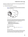
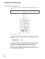
$SSHQGL[$2SWLRQDO$FFHVVRULHVIRUWKH6FDQQLQJ+HDG2)9
$SSHQGL[%%DVLFVRI0HDVXUHPHQW3URFHGXUH
$SSHQGL[&)XQFWLRQDO'HVFULSWLRQRIWKH&RQWUROOHU
$SSHQGL[''HFODUDWLRQRI&RQIRUPLW\
,QGH[
LL
6DIHW\,QIRUPDWLRQ
6DIHW\,QIRUPDWLRQ
/DVHU6DIHW\
The light source of the PSV is a helium neon laser. It is important to
understand that laser light has different properties than ordinary light sources.
Laser radiation is generally extremely intense due to the beam’s low
divergence and great care should be taken when handling laser instruments
that the direct or reflected beam does not enter the eye. To ensure this, the
following precautions have been taken:
In general, Polytec equipment complies with the standards (1
(DIN VDE 0837) and &)5 (US).
The optical output of the laser is less than 1 mW providing the equipment
is used in the manner for which it was intended. This means that the PSV
conforms with ODVHUFODVV,, and is generally very safe. Even when
optimally focused, the laser radiation is not intense enough to harm the
skin.
The scanning head has been equipped with a PHFKDQLFDOEHDPVKXWWHU
which can be used to block the laser beam during the warm-up phase or
when the instrument is not in use, although switched on.
The HPLVVLRQLQGLFDWRU on the scanning head indicates the activity of the
laser and thus potential harm caused by emitted laser beams.
The laser is switched on via a NH\VZLWFK on the controller. The key can
only be removed when the controller is switched off.
It isQRWQHFHVVDU\WRRSHQ the housing of the scanning head when using
the PSV as intended. Opening the housing will invalidate the warranty.
3OHDVHSD\DWWHQWLRQto the following VDIHW\SUHFDXWLRQV when using the
PSV:
Never look directly into the laser beam with the naked eye or with the aid
of mirrors or optical instruments !
Avoid staying in the scanning area ! The laser beam can exit the scanning
head at an angle of ± 20 ° !
Only switch the mechanical beam shutter to the ON position when you are
making measurements !
To position the scanning head, switch the beam shutter to the OFF
position. Only when the head is roughly in place and has been fixed in a
stable position, switch the beam shutter to ON.
Do not use any reflective tools, watches etc. when you are working in the
path of the laser beam !
6DIHW\,QIRUPDWLRQ
/DVHU:DUQLQJ/DEHOV
(&&RXQWULHV
The laser warning labels for the PSV in EC countries are shown in figure 1.1.
Labels 2 and 3 are affixed in the language of the customer’s country. Their
position on the scanning head is shown in figure 1.2.
Figure 1.1: Laser warning labels for the PSV in EC countries
3
1
2
Figure 1.2: Position of the laser warning labels on the scanning head in EC countries
6DIHW\,QIRUPDWLRQ
1RQ(&&RXQWULHV
The laser warning labels for the PSV in non-EC countries are shown in
figure 1.3. Label is affixed only within the USA. Their position on the
scanning head is shown in figure 1.4.
Figure 1.3: Laser warning labels for the PSV in non-EC countries
3
1
2
Figure 1.4: Position of the laser warning labels on the scanning head in non-EC countries
6DIHW\,QIRUPDWLRQ
(OHFWULFDO6DIHW\
The PSV complies with the electrical safety class I. Electrical shock protection
is achieved by a fully metallic housing connected to protective ground.
3OHDVHSD\DWWHQWLRQ to the following VDIHW\SUHFDXWLRQV when using the
PSV:
The PSV controller and the workstation should only be connected via
three pin mains cables to an AC mains supply 50 / 60 Hz with a grounded
protective conductor with a nominal voltage which corresponds to the
voltage set on the voltage selector.
The mains voltage input of the workstation can also be designed as a wide
range input like the junction box and therefore be connected to all mains
voltages with nominal values between 100 V and 240 V.
Defective mains fuses may only be replaced by fuses of the same kind
with their rating given on the back.
The PSV must not be used with open housing. As a general rule, before
removing parts of the housing, the mains cable has to be unplugged.
Air inlets and outlets must always be kept uncovered to ensure effective
cooling. If the cooling fan stops working, the PSV is to be switched off
immediately.
,QWURGXFWLRQ
,QWURGXFWLRQ
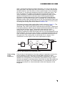
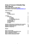
$UHDRI$SSOLFDWLRQDQG6\VWHP6XPPDU\
The 3olytec 6canning 9ibrometer 369 measures the two-dimensional
distribution of vibration velocities on the basis of laser interferometry. The
system components are shown in figure 2.1.
S c a n n in g H e a d
W o r k s ta tio n
J u n c tio n B o x
C o n tr o lle r
Figure 2.1: System components of the PSV
The interferometer signal is decoded in the FRQWUROOHU with the velocity
decoder. An analog voltage signal is thus generated which is proportional to
the vibration velocity.
The MXQFWLRQER[ is the central connection point between the system
components and provides the interfaces for peripheral devices.
The VFDQQLQJKHDG consists of the interferometer, the scanners to deflect the
laser beam and a video camera to visualize the measurement object.
The measurement data is digitally recorded in the ZRUNVWDWLRQ. The software
controls the data acquisition and offers user-friendly functions to evaluate the
measurement data.
,QWURGXFWLRQ
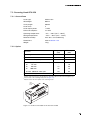
7KH5DQJHRIWKH3690RGHOV
The decoders and filters in the controller as well as the data acquisition board
in the workstation determine the characteristics of the PSV. Depending on the
application there are three different models on offer; their characteristics are
summarized in table 2.1.
Table 2.1: Summary of the PSV models
PSV Model
Controller Velocity decoder
Measurement ranges
PSV 300-U
Universal
OVD-04 +PLL-DC OVD-04 HF+ PLL-DC OVD-04 (+ PLL-DC) 1
1 / 5 / 10 / 25 / 125 /
1 000
(1 / 5) 1 10 / 25 / 125
250 kHz
1.5 MHz
250 kHz
400 Hz ... 102 kHz
5 / 20 / 100 kHz
5 / 20 / 100 kHz
PCI-6111
PCI-4451
80 kHz
1 MHz
40 kHz
Input channels
simultaneously
4
2
2
Output channels of the
internal function generator
3
1
(1) 1
⁄V
Maximum frequency
Filter
Digital
Data acquisition board
signal
Internal function generator
processing
Maximum bandwidth
The information in brackets is optional.
PSV 300-F
High Frequency
1 / 5 / 10 / 25 / 125 /
1 000
mm
--------s-
1
PSV 300-H
High Performance
PCI-4452
PCI-6711
)LUVW6WHSV
)LUVW6WHSV
2SHUDWLQJDQG0DLQWHQDQFH5HTXLUHPHQWV
2SHUDWLQJ
HQYLURQPHQW
The PSV can be operated in dry rooms under normal climate conditions (refer
to specifications in chapter 7). In particular the optical components in the
scanning head are sensitive to moisture, high temperature, jolting and dirt. A
sufficient acclimatization period should be allowed for before switching the
PSV on. Avoid condensation on the optical components caused by a rapid
change in temperature.
0DLQV
FRQQHFWLRQ
Before taking the PSV into operation, please ensure that the supply voltage
set with the voltage selectors of the controller and the workstation
corresponds with the local mains voltage. Only replace defective fuses by
fuses of the same kind and equal rating.
The mains voltage input of the workstation can also be designed as a wide
range input and therefore be connected to all mains voltages with nominal
values between 100 V and 240 V.
$VVHPEO\
The scanning head must not be positioned provisionally but mounted properly
on a stable tripod using the threads provided.
&RQQHFWLQJ
FDEOHV
As a general rule the PSV must not be switched on until all cables have been
connected. Make sure that all jack connections are connected properly and
firmly. Plug in the SCSI-type connectors of the acquisition cable with great
care at the right angles. Only use original RS-232 cables from Polytec for the
RS-232 connections (1:1 wired). Protect all cables from mechanical damage
and from high temperatures.
:DUPLQJXS
The helium-neon laser in the scanning head requires a certain period of time
to reach optimum stability. The PSV should thus be switched on 30 minutes
before the first measurements are made to ensure that it is in thermal
equilibrium with the surroundings.
&RROLQJ
It is very important to ensure that there is sufficient air circulation to keep the
system components cool. The air vents of the scanning head must never be
covered up and the back panels of the electronics cabinets must be at least
50 mm away from the wall.
&OHDQLQJ
The housing surfaces of the instrument can be cleaned with mild detergent
solutions. Organic solvents must not be used.
3DQWLOWVWDJH
Avoid any additional weight on the pan-tilt stage by placing objects on top of
the scanning head or attaching things to it as this can put strain on the pan-tilt
stage.
,QVWDOOLQJ
RWKHU
FRPSRQHQWV
Always contact Polytec prior to connecting any other hardware or software
components to the PSV which are not part of it as this is likely to damage the
system and could invalidate the warranty.
)LUVW6WHSV
2SHQLQJXS
Opening up of the equipment without authorization is not necessary for its
WKHHTXLSPHQW operation and will invalidate the warranty.
8QSDFNLQJDQG,QVSHFWLRQ
8QSDFNLQJ
The PSV consists of the following components:
controller OFV-3001 S
scanning head OFV-056
junction box PSV-Z-040 (-H, -F, -U)
workstation with keyboard and mouse
monitor with monitor cable and mains cable
tripod with fluid stage OFV-S2
umbilical cable
interferometer cable
video cable
acquisition cable
DIO / DAC cable
BNC cable
2 RS-232 cables (1:1 wired)
3 mains cables
PSV 300-H, -F: hand set PSV-Z-051
optional
TFT monitor with monitor cable and mains cable
heavy duty tripod with motorized pan-tilt stage, connector box and mains
cable PSV-Z-017 (instead of the OFV-S2)
PSV 300-H: generator cable for the internal function generator
PSV 300-U: hand set PSV-Z-051
coaxial unit OFV-056-C
acoustic gate unit PSV-Z-EQ with BNC cable
system cabinet PSV-Z-035
hand set OFV-310
vertical test stand PSV-Z-018
&DXWLRQ Protect the unpacked scanning head from hard jolts as these can lead to misalignment of
the interferometer !
,QVSHFWLRQ
Please pay attention to the following steps when unpacking the PSV:
1. Check the packaging for signs of unsuitable handling during transport.
2. After unpacking, check all components for external damage (scratches,
loose screws etc.).
3. In the case of a wrong delivery, damage or missing parts, inform your local
Polytec representatives immediately and give them the serial numbers of
the instruments. The identification labels can be found on the back of the
instruments and also on the inside cover of this manual.
)LUVW6WHSV
4. Carefully retain the original packaging in case you have to return the PSV.
Install the PSV as described in section 3.4 and carry out a functional test as
described in section 3.5.
&RQWURO(OHPHQWV
&RQWUROOHU
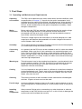
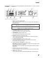
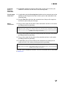
)URQWSDQHO
1
The front panel of the controller is shown in figure 3.1.
2
4
3
5
6
7
V E L O C IT Y
O F V 3 0 0 1 S
V IB R O M E T E R C O N T R O L L E R
+
F U N C T IO N
-
P O W E R
O U T P U T
O V E R
S E T T IN G
D IS P L A C E M E N T
C L E A R
O
L L O
I
R E S E T
R E M O T E
1 3
1 2
1 1
O U T P U T
1 0
9
8
Figure 3.1: Front view of the controller
32:(5 LED
The L ED lights up when the key switch on the controller is turned to
position I and indicates that the controller is ready to operate.
0DLQVVZLWFK
This key switch disconnects the vibrometer from the mains (position O)
and is used to turn it off in the case of danger.
&DXWLRQ $OZD\V connect all connecting cables EHIRUH switching the controller on !
/LTXLG&U\VWDO'LVSOD\/&' with background lighting
This display shows the settings of the controller. The organization of the
display and how to use it to operate the controller without the software are
described in section 5.12.
)81&7,21 keys
These keys do not have a function, when the controller is operated via the
software. When the controller is operated without the software, the cursor
is moved up and down on the display using the ↑ and ↓ keys (refer to
section 5.12.1).
)LUVW6WHSV
6(77,1* keys
These keys do not have a function, when the controller is operated via the
software. When the controller is operated without the software, these keys
are used to change the settings (refer to section 5.12.1).
29(5 indicator for the velocity
The LED lights up when the output voltage exceeds either the positive or
negative full scale range (peak) of the velocity decoder. If it lights up
permanently, the next highest range must be selected (refer to
section 4.2.1).
Analog voltage output for the 9(/2&,7< signal (BNC jack)
The voltage at this output is proportional to the instantaneous vibration
velocity of the object to be measured. The voltage is positive if the object
is moving towards the scanning head.
&/($5 socket for the displacement decoder (BNC jack)
This socket allows synchronized resetting of the optional displacement
decoder. This input is only active if a displacement decoder is installed.
Analog voltage output for the ',63/$&(0(17 signal (BNC jack)
The voltage at this output is proportional to the instantaneous
displacement of the object to be measured. The output is only active if a
displacement decoder is installed.
&/($5 key for the displacement decoder
Using this key the optional displacement decoder can be reset manually.
5(6(7 key
The controller processor can be reset using this key.
5(027( L ED
The L ED lights up if the controller is being operated remotely via one of the
interfaces. Manual operation with the keys ↑, ↓, +, − on the front panel is
also possible, however, manual settings are not transferred to the
software.
//2 LED
This LED lights up when the status /OCAL /OCK 2UT has been activated
via the software. The keys ↑, ↓, +, − on the front panel are then
deactivated and the controller is operated exclusively via the software.
)LUVW6WHSV
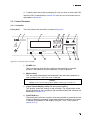
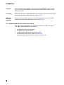
%DFNSDQHO
The back panel of the controller is shown in figure 3.2.
5
4
R S 2 3 2
G P IB / IE E E -4 8 8
S IG N A L
3
1
IN T E R F E R O M E T E R
E X T . D E C .
R E M O T E F O C U S
6
2
7
8
Figure 3.2: Rear view of the controller
0DLQVFRQQHFWLRQcombination
Socket for standard power cord with built-in fuses and mains voltage
selector
:DUQLQJ $OZD\V disconnect from the mains EHIRUH checking the fuses !
&DXWLRQ $OZD\V check the settings of the voltage selector and the rating of the fuses EHIRUH
connecting to the mains !
,17(5)(520(7(5 connector (Sub-D jack)
Jack for the interferometer cable to the junction box
56 interface (9-pin Sub-D jack)
Jack for the RS-232 cable to the workstation to control the PSV with the
software
1RWH To control the PSV using the software, in the controller the transfer rate must be set to
%DXG (refer to section 5.12.3) !
&RROLQJIDQ
&DXWLRQ This opening must DOZD\V be kept free to ensure sufficient cooling ! The distance from the
wall should be at least 50 mm !
,((( *3,% interface
6,*1$/ output (BNC jack)
The DC voltage at this output is proportional to the logarithm of the optical
signal level.
)LUVW6WHSV
5(027()2&86 interface (7-pin circular jack)
Interface for the optional hand set OFV-310 to focus the laser beam (refer
to section A.3)
External decoder interface (;7'(& (optional)
Interface for an external digital displacement decoder
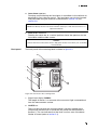
6FDQQLQJ+HDG
On the underside of the scanning head, there is a 4-pin circular jack for the
cable to the optional pan-tilt stage PSV-Z-017.
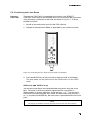
)URQWSDQHO
The front panel of the scanning head is shown in figure 3.3.
3
4
2
2
1
5
R E M O T E
C O N T R O L
Figure 3.3: Front view of the scanning head
Connector 5(027(&21752/ for the hand set PSV-Z-051
(12-pin circular connector)
The hand set is used for focusing and positioning the laser beam (refer to
section 5.6 and section 5.8).
Mounting holes for the optional FRD[LDOXQLW OFV-056-C
The optional coaxial unit is used for scanning small parts at short distance
(refer to section A.1).
9LGHRFDPHUD front lens
The video camera is controlled via the software as described in your
software manual.
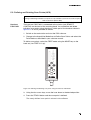
)LUVW6WHSV
/DVHUEHDP aperture
Focusing and positioning the laser beam is controlled via the software as
described in your software manual. The laser beam can also be focused
and positioned using the hand set as described in section 5.6 and
section 5.8.
:DUQLQJ 1HYHU look directly into the laser beam with the naked eye or with the aid of mirrors or
optical instruments !
'XVWFRYHU switch bar
Rotating the switch bar to a vertical position closes the apertures for the
laser beam and the video camera.
&DXWLRQ To protect the lenses and scanner mirrors, RQO\ open the dust cover when your are making
measurements!
%DFNSDQHO
The back panel of the scanning head is shown in figure 3.4.
4
3
E m is s io n
2
O N
O F F
1
L A S E R
S
G
N
A
I
5
L
Figure 3.4: Rear view of the scanning head
Signal level display 6,*1$/
The length of the bar is a measure of the amount of light scattered back
from the measurement surface.
/$6(5 L ED
The L ED lights up when the scanning head is correctly cabled to the
junction box and the laser is turned on (key switch on the controller in
position I). The LED indicates that the laser is active, even if the beam
shutter is closed (refer to section 5.2).
)LUVW6WHSV
Beam shutter (0,66,2121 2))
In position OFF the laser beam is blocked.
:DUQLQJ 2QO\ switch the beam shutter to the ON position when you are making measurements !
$LUYHQWV
&DXWLRQ This opening must DOZD\V be kept free to ensure sufficient cooling !
0DLQFRQQHFWRU (industrial-style)
Jack for the umbilical cable to the junction box
-XQFWLRQ%R[
)URQWSDQHO
IRUPRGHO+
The front panel of the junction box for the PSV model -H is shown in
figure 3.5.
2
1
J U N C T IO N
P S V -Z -0 4 0 -H
B O X
3
4
5
6
T T L
P A N /T IL T
S Y N C O U T
7
8
A N A L O G
S O U R C E
T R IG
IN
IN
O U T 1
R E F 1
V E L O
G A T E IN
O U T 2
R E F 2
R E F 3
P O W E R
A U X O U T
3
2
1 2
1 1
1 0
9
9
Figure 3.5: Front view of the junction box for the PSV model -H
32:(5 LED
The LED lights up when the junction box is correctly cabled to the
controller and the key switch on the controller is turned to position I. The
L ED indicates that the junction box is ready to operate.
Control keys for the SDQWLOWKHDG, pan
Using these keys the optional pan-tilt stage is panned clockwise (→) or
anti-clockwise (←) (refer to section 5.4). Alternatively it can be controlled
via the software as described in the software manual.
Control keys for the SDQWLOWKHDG, tilt
Using these keys the optional pan-tilt stage is tilted upward (↑) or
downward (↓) (refer to section 5.4). Alternatively it can be controlled via
the software as described in the software manual.
TTL output 6<1&287 (BNC jack)
Synchronization pulse for the generator signal.
)LUVW6WHSV
TTL input 75,*,1 (BNC jack)
TTL input for an external trigger signal
Generator output 287 (BNC jack)
Output signal of the internal function generator.
Analog input 5() (BNC jack)
Analog input for the reference signal
Analog input 9(/2 for the velocity signal (BNC jack)
Analog input for the velocity signal from the controller
Analog inputs 5() and 5() (BNC jack)
Analog inputs for 2 additional reference signals
Generator output 287 (BNC jack)
Additional output signal of the internal function generator
TTL input *$7(,1 (BNC jack)
TTL input for an external gating signal.
TTL output $8;287 (BNC jack)
TTL output for special applications, programmable via the optional
Visual Basic Engine PSV-Z-082
)URQWSDQHOIRU The front panel of the junction box for the PSV models -F and -U is shown in
PRGHOV)8
figure 3.6.
2
1
P S V -Z -0 4 0 -F
J U N C T IO N B O X
3
4
7
6
5
T T L
P A N /T IL T
A U X IN
T R IG
IN
S O U R C E
IN P U T
S IG N A L
V E L O
S Y N C
R E F
P O W E R
A U X O U T
3
2
G A T E IN
1 1
1 0
9
8
Figure 3.6: Front view of the junction box for the PSV models -F and -U
32:(5 LED
The L ED lights up when the junction box is correctly cabled to the
controller and the key switch on the controller is turned to position I. The
L ED indicates that the junction box is ready to operate.
Control keys for the SDQWLOWKHDG, pan
Using these keys the optional pan-tilt stage is panned clockwise (→) or
anti-clockwise (←) (refer to section 5.4). Alternatively it can be controlled
via the software as described in the software manual.
)LUVW6WHSV
Control keys for the SDQWLOWKHDG, tilt
Using these keys the optional pan-tilt stage is tilted upward (↑) or
downward (↓) (refer to section 5.4). Alternatively it can be controlled via
the software as described in the software manual.
TTL input $8;,1 (BNC jack)
TTL input for special applications
TTL input 75,*,1 (BNC jack)
TTL input for an external trigger signal
Generator output 6,*1$/ (BNC jack)
Output signal of the internal function generator.
3698 The output is only active if the corresponding option is
installed.
Analog input 9(/2 for the velocity signal (BNC jack)
Analog input for the velocity signal from the controller
Analog input 5() (BNC jack)
Analog input for the reference signal
TTL output 6<1& (BNC jack)
Synchronization pulse for the generator signal.
3698 The output is only active if the corresponding option is
installed.
TTL input *$7(,1 (BNC jack)
TTL input for an external gating signal.
3698 The input is only active if the corresponding option is
installed.
TTL output $8;287 (BNC jack)
TTL output for special applications, programmable via the optional
Visual Basic Engine PSV-Z-082
)LUVW6WHSV
%DFNSDQHOIRU The back panel of the junction box for the PSV models -H, -F and -U is shown
DOOPRGHOV
in figure 3.7.
6
O P T IO N
7
8
P C
R S 2 3 2
9
V ID E O
S C A N N IN G
H E A D
1
B O A R D
V IB R O M E T E R
A C Q U IS IT IO N
2
D IO
/ D A C
3
5
4
3
2
1
Figure 3.7: Rear view of the junction box
0DLQVFRQQHFWLRQFRPELQDWLRQ
Mains socket with built-in fuses. The mains voltage input is designed as a
wide range input.
:DUQLQJ $OZD\V disconnect from the mains EHIRUH checking the fuses !
&DXWLRQ $OZD\V check the fuses EHIRUH installing the PSV !
6&$11,1*+($' connector (industrial-style)
Jack for the umbilical cable to the scanning head
9,%520(7(5 connector (Sub-D jack)
Jack for the interferometer cable to the controller
',2 '$& connector (37-pin Sub-D jack)
Jack for the DIO / DAC cable to the workstation to control the scanner
mirrors and the pan-tilt stage
$&48,6,7,21%2$5' connector (SCSI-II type)
Jack for the acquisition cable to the workstation to transmit both
measurement and control signals
Optional connectors 237,21 (BNC jacks)
369+ Connectors for the generator cable to the workstation for the
internal function generator (optional)
369)8 Up to three BNC jacks can be made available for special
applications.
56 interface (9-pin Sub-D connector)
Jack for the RS-232 cable to the workstation to control the video camera
9,'(2 output (BNC jack)
Jack for the video cable to transmit the video signal to the workstation
)LUVW6WHSV
&RROLQJIDQ
&DXWLRQ This opening must DOZD\V be kept free to ensure sufficient cooling ! The distance from the
wall should be at least 50 mm !
:RUNVWDWLRQ
)URQWSDQHO
IRUDOOPRGHOV
The front panel of the workstation for the PSV models -H, -F and -U is shown
in figure 3.8. The lockable front flap is shown as transparent.
1
2
7
6
3
4
5
Figure 3.8: Front view of the workstation
&RROLQJIDQ
&DXWLRQ This opening must DOZD\V be kept free to ensure sufficient cooling !
32:(5 and +'' LED
The green LED (POWER) lights up when the workstation is switched on
using the mains switch on the back and when the black key on the front is
pressed. The red LED being lit indicates the activity of the hard disk drive
(HDD) in the workstation.
5(6(7 key
Using this key the control processor of the workstation can be reset and
the workstation can be restarted. The setting of the workstation is
subsequently the same as it was straight after switching on. You can
press this key through the opening using a thin object.
)LUVW6WHSV
GLVNGULYH
&'520 drive or rewriter
You will find an exact description of the drive in the user manual of the
manufacturer.
2Q 2II key
Pressing the black key, the workstation will be switched on or off.
/RFNZLWKNH\ in the front flap
To secure the workstation for unauthorized using, the front flap can be
locked using the key.
%DFNSDQHOIRU The back panel of the workstation for the PSV model -H is shown in
PRGHO+
figure 3.9. The order of the boards can be different from the picture.
1 4
1
C O M
2
3
4
5
6
7
1
C O M
2
8
9
1 0
1 1
1 2
D A C
A C Q U IS IT IO N
M O N IT O R
M O U S E
I
K E Y B O A R D
O
P R I N T E R
G E N E R A T O R
A V
1 4
1 3
Figure 3.9: Rear view of the workstation for the PSV model -H
0DLQVFRQQHFWLRQFRPELQDWLRQ
Mains socket with a mains switch and mains voltage selector. Instead of
using the voltage selector, the mains voltage input can also be designed
as a wide range input (refer to section 3.1). The mains switch disconnects
the workstation from the mains (position O) and is used to turn it off in
case of danger.
&DXWLRQ If applicable, DOZD\V check the setting of the mains voltage selector EHIRUH connecting the
workstation to the mains !
)LUVW6WHSV
0286( connector (6-pin circular jack)
.(<%2$5' connector (6-pin circular jack)
1HWZRUN connector
Jack of the Ethernet network board
86% port (Universal Serial Bus)
Alternative jack for peripheral devices like mouse, keyboard, etc.
Serial interface &20 (9-pin Sub-D connector)
Jack for the RS-232 cable to the junction box to control the video camera
Parallel 35,17(5 connector (25-pin Sub-D jack)
Serial interface &20 (9-pin Sub-D connector)
Jack for the RS-232 cable to the controller to control the PSV via the
software
$9 connector (9-pin Sub-D jack)
Jack for the video cable to the junction box to transmit the video signal
021,725 connector (15-pin Sub-D jack)
*(1(5$725 connector for the internal function generator (SCSI-II type)
Jack for the generator cable of the internal function generator to the
junction box
$&48,6,7,21 connector for the data acquisition (VHDIC type)
Jack for the Y-shaped acquisition cable to the junction box to transmit
both measurement and control signals
'$& connector (62-pin Sub-D jack)
Jack for the DIO / DAC cable to the junction box to control the scanner
mirrors and the pan-tilt stage
$LUYHQWV
&DXWLRQ These openings must DOZD\V be kept free to ensure sufficient cooling ! The distance from
the wall should be at least 50 mm !
)LUVW6WHSV
%DFNSDQHOIRU The back panel of the workstation for the PSV models -F and -U is shown in
PRGHOV)8 figure 3.10. The order of the boards can be different from the picture.
1 3
1
C O M
2
3
4
5
6
7
8
1
C O M
M O N IT O R
M O U S E
I
K E Y B O A R D
O
P R I N T E R
2
9
1 0
1 1
D A C
A C Q U IS IT IO N
A V
1 3
1 2
Figure 3.10: Rear view of the workstation for the PSV models -F and -U
0DLQVFRQQHFWLRQFRPELQDWLRQ
Mains socket with a mains switch and mains voltage selector. Instead of
using the voltage selector, the mains voltage input can also be designed
as a wide range input (refer to section 3.1). The mains switch disconnects
the workstation from the mains (position O) and is used to turn it off in
case of danger.
&DXWLRQ If applicable, DOZD\V check the setting of the mains voltage selector EHIRUH connecting the
workstation to the mains !
0286( connector (6-pin circular jack)
.(<%2$5' connector (6-pin circular jack)
1HWZRUN connector
Jack of the Ethernet network board
86% port (Universal Serial Bus)
Alternative jack for peripheral devices like mouse, keyboard, etc.
Serial interface &20 (9-pin Sub-D connector)
Jack for the RS-232 cable to the junction box to control the video camera
)LUVW6WHSV
Parallel 35,17(5 connector (25-pin Sub-D jack)
Serial interface &20 (9-pin Sub-D connector)
Jack for the RS-232 cable to the controller to control the PSV via the
software
$9 connector (9-pin Sub-D jack)
Jack for the video cable to the junction box to transmit the video signal
021,725 connector (15-pin Sub-D jack)
$&48,6,7,21 connector for the data acquisition (SCSI-II type)
Jack for the acquisition cable to the junction box to transmit both
measurement and control signals
3698 The PSV model -U has two VHDIC connectors instead of the
SCSI-II type connector (refer to PSV model -H).
'$& connector (62-pin Sub-D jack)
Jack for the DIO / DAC cable to the junction box to control the scanner
mirrors and the pan-tilt stage
$LUYHQWV
&DXWLRQ These openings must DOZD\V be kept free to ensure sufficient cooling ! The distance from
the wall should be at least 50 mm !
)LUVW6WHSV
,QVWDOODWLRQ
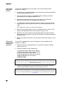
0HFKDQLFDO$VVHPEO\
6FDQQLQJ
KHDG
The scanning head is mounted on either a tripod with fluid stage (OFV-S2) or
a heavy duty tripod with motorized pan-tilt stage (optional PSV-Z-017). The
heavy-duty tripod can also be mounted on a trolley (optional). The scanning
head mounted on the fluid stage and on the tripod is shown in figure 3.11.
Figure 3.11: Scanning head mounted on the fluid stage and on the tripod
Before attempting to mount the scanning head, all locking mechanisms of the
trolley and the tripod, particularly screws, should be checked to make sure
they are tight. A loose screw may cause the stand to be unstable and possibly
collapse.
1RWH It is best to carry out the following assembly when someone is there to help you !
)LUVW6WHSV
7ULSRGZLWK
IOXLGVWDJH
2)96
If your PSV is equipped with a fluid stage, you must proceed with the
assembly as follows:
1. Assemble the tripod as described in the assembly instructions provided by
the manufacturer MANFROTTO.
2. Then mount the fluid stage as described in the assembly instructions
provided by the manufacturer MANFROTTO.
3. Open the locking mechanism on the fluid stage by simultaneously
pressing the safety latch and opening the safety lever.
4. A suitable quick release hexagonal plate has been pre-mounted on the
scanning head. Use this plate to position the scanning head on the fluid
stage.
7KHVDIHW\OHYHUFOLFNVLQWRSODFHDXWRPDWLFDOO\
5. Ensure that the quick release plate is attached all the way around. This
needs to be done before the scanning head is ready to use.
6. Whenever you want to remove the scanning head from the fluid stage,
one person should hold the scanning head while the second person opens
the safety lever.
7. Keep the assembly instructions for the tripod and the fluid stage in a safe
place.
7ULSRGZLWK
SDQWLOWVWDJH
369=
RSWLRQDO
If your PSV is equipped with a pan-tilt stage you must proceed with the
assembly as follows:
1. Unpack the pan-tilt stage and check it for external damage (scratches,
loose screws, etc.).
2. Check the contents of the assembly kit:
1
1
3
1
2
1
1
Adapter plate with 3 Allen screws M6 x 16
Connector box with 4 Allen screws M8 x 40
Allen screws M8 x 16 with washers
Mounting plate with 2 Allen screws M6 x 20
Allen screws M6 x 16 with washers
Allen key size 5
Allen key size 6
&DXWLRQ Make sure that the screws are always tightened, to ensure that the system is both stable
and functions accurately !
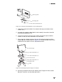
3. Attach the mounting plate on the underside of the scanning head with
2 Allen screws M6 x 20. To do this use the Allen key size 5.
&DXWLRQ Make sure that the mounting plate is correctly aligned ! The FRONT labeled side of the plate
has to be mounted in the direction of the front panel of the scanning head as shown in
figure 3.12.
)LUVW6WHSV
S c a n n in g h e a d
M o u n tin g p la te
2 A lle n s c r e w s M 6 x 2 0
Figure 3.12: Fixing the mounting plate on the scanning head
4. Unpack the tripod and check it for external damage (scratches, loose
screws, etc.).
5. Assemble the tripod as described in the assembly instructions from the
manufacturer MANFROTTO.
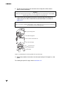
6. Unscrew the plate on the top of the tripod and keep the plate and the
screws in case you may need them at a later date.
7. Now mount the adapter plate on the top of the tripod using the 3 Allen
screws M6 x 16 as also shown in figure 3.13. Ensure that the knob on the
underside of the tripod is always tightened securely.
P a n - tilt s ta g e
3 A lle n s c r e w s M 8 x 1 6
4 A lle n s c r e w s M 8 x 4 0
C o n n e c to r b o x
3 A lle n s c r e w s M 6 x 1 6
A d a p te r p la te
T r ip o d
Figure 3.13: Mounting the pan-tilt stage on the tripod
8. Screw the connector box on the adapter plate using the 4 Allen screws
M8 x 40. To do this, use the Allen key size 6.
)LUVW6WHSV
9. Fix the pan-tilt stage on the connector box using the 3 Allen screws
M8 x 16 and the washers.
&DXWLRQ Make sure that the pan-tilt stage is correctly aligned to the connector box ! The FRONT
labeled sides have to be mounted in the same direction.
10. Then mount the scanning head with its mounting plate on the pan-tilt
stage using the 2 Allen screws M6 x 16 and the washers as shown in
figure 3.14.
&DXWLRQ Make sure that the FRONT labeled sides of the components are mounted in the direction of
the front panel of the scanning head !
S c a n n in g h e a d
M o u n tin g p la te
2 A lle n s c r e w s M 6 x 1 6
P a n - tilt s ta g e
C o n n e c to r b o x
A d a p te r p la te
T r ip o d
Figure 3.14: Mounting the scanning head on the pan-tilt stage
11. Keep the assembly instructions for the tripod and pan-tilt stage in a safe
place.
For cabling the pan-tilt stage, refer to section 3.4.2.
)LUVW6WHSV
6\VWHP
FDELQHW
369=
RSWLRQDO
You receive the system cabinet PSV-Z-035 ready assembled. The positions of
the individual system components in the cabinet is shown in figure 3.15.
1. Undo the housing feet of the system components and keep the housing
feet and the screws in a safe place.
2. Place the controller at the bottom as the air vents are situated in the
bottom plate.
&DXWLRQ To ensure sufficient cooling, the controller must be situated at the bottom and the junction
box at the top of the system cabinet !
3. Insert the workstation above the controller.
4. Are the air vents of your junction box in the top plate ? If not, please
exchange the top and bottom plate.
5. Insert the junction box above the workstation.
6. Fix all front panels with the screws provided.
7. Place the other system components as shown in figure 3.15.
M o n ito r
K e y b o a rd
M o u s e
J u n c tio n B o x
W o r k s ta tio n
C o n tr o lle r
Figure 3.15: Position of the PSV components on the system cabinet
)LUVW6WHSV
All system components should now be correctly mounted.
&DEOLQJ
The individual steps on cabling the PSV are described in the following. The
complete cabling is shown in figure 3.16 to figure 3.18. All connections must
be made easily. If not, check the plugs for bent contact pins to avoid serious
damage being incurred. Secure the connections correspondingly. Should any
problems occur in cabling, please contact your local Polytec representative.
&DXWLRQ $OZD\V connect all components to each other EHIRUH plugging in the mains cables !
:RUNVWDWLRQ
1. Connect the keyboard to the socket KEYBOARD on the back of the
workstation.
2. Connect the mouse to the socket MOUSE on the back of the workstation.
3. Plug the monitor cable into the back of the monitor and into the socket
MONITOR on the back of the workstation.
&RQWUROOHU⇔
ZRUNVWDWLRQ
4. To operate the controller via the software, plug an 56 cable into the
jack RS 232 on the back of the controller and into either of the jacks
COM1 or COM2 on the back of the workstation.
&RQWUROOHU⇔
KDQGVHW
2)9
5. If applicable, connect the optional hand set OFV-310 to the circular jack
REMOTE FOCUS on the back of the controller.
&RQWUROOHU⇔
MXQFWLRQER[
6. Plug the ,QWHUIHURPHWHU cable into the Sub-D jack INTERFEROMETER
on the back of the controller and into the Sub-D jack VIBROMETER on the
back of the junction box.
7. For transmission of the velocity signal, plug the %1& cable into the BNC
jack VELOCITY OUTPUT on the front of the controller and into the BNC
jack VELO on the front of the junction box.
5HIHUHQFH
VLJQDO
8. 369+ If required, connect the reference signal to the BNC jack
REF 1 on the front of the junction box for the model -H.
369)8 If required, connect the reference signal to the BNC jack
REF on the front of the junction box for the models -F and -U.
9. 2QO\369+ You can connect two additional reference signals to the
BNC jacks REF 2 and REF 3 on the front of the junction box for the model
-H.
([WHUQDO
WULJJHU
10. If required, connect the external trigger signal to the BNC jack TRIG IN on
the front of the junction box.
)LUVW6WHSV
J U N C T IO N B O X
P S V -Z -0 4 0
O P T IO N
P C
R S 2 3 2
V ID E O
S C A N N IN G
A C Q U IS IT IO N
B O A R D
2
D IO
/ D A C
3
H E A D
V IB R O M E T E R
1
C O N T R O L L E R
O F V -3 0 0 1 S
G P IB / IE E E -4 8 8
S IG N A L
IN T E R F E R O M E T E R
R S 2 3 2
R E M O T E F O C U S
E X T . D E C .
H A N D S E T
O F V - 3 1 0 ( o p tio n a l)
C O M
1
K E Y B O A R D
C O M
2
D A C
A C Q U IS IT IO N
G E N E R A T O R
P R I N T E R
M O N IT O R
I
K E Y B O A R D
O
M O U S E
A V
W O R K S T A T IO N
P S V -P C
M O N IT O R
M O U S E
Figure 3.16: Cabling of the controller’s back panel
)LUVW6WHSV
R E F E R E N C E S IG N A L
M o d e l -H
S IG N A L O U T P U T S
F U N C T IO N G E N E R A T O R
E X T E R N A L T R IG G E R
S Y N C
P U L S E
P A N /T IL T
P S V -Z -0 4 0 -H
J U N C T IO N B O X
T T L
A N A L O G
S O U R C E
S Y N C O U T
IN
IN
O U T 1
R E F 1
V E L O
G A T E IN
O U T 2
R E F 2
R E F 3
T R IG
P O W E R
A U X O U T
A C O U S T IC
G A T E U N IT
A D D IT IO N A L
R E F E R E N C E S IG N A L S
M o d e ls -F a n d -U
S IG N A L O U T P U T
F U N C T IO N G E N E R A T O R
E X T E R N A L T R IG G E R
T T L
P A N /T IL T
P S V -Z -0 4 0 -F
J U N C T IO N B O X
A U X IN
T R IG
IN
S O U R C E
IN P U T
S IG N A L
V E L O
S Y N C
R E F
P O W E R
A U X O U T
A C O U S T IC
G A T E IN
G A T E U N IT
S Y N C
P U L S E
R E F E R E N C E S IG N A L
V E L O C IT Y
O F V 3 0 0 1 S
V IB R O M E T E R C O N T R O L L E R
+
F U N C T IO N
-
P O W E R
O U T P U T
O V E R
S E T T IN G
D IS P L A C E M E N T
C L E A R
O
I
L L O
R E M O T E
R E S E T
O U T P U T
Figure 3.17: Cabling of the front panels of the controller and the junction box
,QWHUQDO
IXQFWLRQ
JHQHUDWRU
11. 369+ If required, the signal of the internal function generator is
available at the BNC jacks OUT 1 and OUT 2 on the front of the junction
box for the model -H and at the BNC jack OUT 3 of the generator cable.
369)8 If required, the signal of the internal function generator is
available at the BNC jack SIGNAL on the front of the junction box for the
models -F and -U.
)LUVW6WHSV
12. 369+ If required, the synchronized pulse of the generator signal is
available at the BNC jack SYNC OUT on the front of the junction box.
369)8 If required, the synchronized pulse of the generator signal
is available at the BNC jack SYNC on the front of the junction box.
$FRXVWLF
JDWH XQLW
13. If applicable, connect the optional acoustic gate unit PSV-Z-EQ to the
BNC jack GATE IN on the front of the junction box.
-XQFWLRQER[ 14. To control the video camera, plug an 56 cable into the jack RS 232
⇔ ZRUNVWDWLRQ
on the back of the junction box and into either of the jacks COM 1 or
COM 2 on the back of the workstation.
15. Plug the 9LGHR cable into the BNC jack VIDEO on the back of the junction
box and into the 9-pin Sub-D jack AV on the back of the workstation.
&DXWLRQ Plug in the SCSI-type connectors with great care at the right angles so as not to damage
them !
16. 369+8 Plug the Y-shaped $FTXLVLWLRQ cable into the SCSI-type
connector ACQUISITION BOARD on the back of the junction box and into
the two VHDIC-type connectors ACQUISITION on the back of the
workstation.
369) Plug the $FTXLVLWLRQ cable into the SCSI-type connector
ACQUISITION BOARD on the back of the junction box and into the
SCSI-type connector ACQUISITION on the back of the workstation.
17. Plug the ',2 '$& cable into the 37-pin Sub-D jack DIO / DAC on the back
of the junction box and into the 62-pin Sub-D jack DAC on the back of the
workstation.
18. 2QO\369+ If required, plug the *HQHUDWRU cable into the three
BNC jacks OPTION 1, 2 and 3 on the back of the junction box and into the
SCSI-type connector GENERATOR on the back of the workstation.
&DXWLRQ The cable numbers of the generator cable have to be in accordance with the corresponding
number of the jack (OPTION 1, 2 or 3) on the junction box !
-XQFWLRQER[
⇔VFDQQLQJ
KHDG
19. The umbilical cable has both a jack with a straight cable exit and a jack
with a cable exit on the side. The cabling can be freely selected
depending on the way the scanning head has been mounted. Plug the
8PELOLFDO cable into the industrial-style connector on the back of the
scanning head and into the industrial-style connector SCANNING HEAD
on the back of the junction box.
)LUVW6WHSV
S C A N N IN G
O F V -0 5 6
H E A D
E m is s io n
O N
O F F
L A S E R
S
G
R E M O T E
C O N T R O L
I
A
N
L
P A N -T IL T S T A G E
S IG N A L O U T P U T
F U N C T IO N G E N E R A T O R
O U T 3
H A N D S E T
P S V -Z -0 5 1
J U N C T IO N B O X
P S V -Z -0 4 0 -H , -F , -U
O P T IO N
V ID E O
S C A N N IN G
1
A C Q U IS IT IO N B O A R D
O P T IO N 2
O P T IO N 3
P C
R S 2 3 2
2
D IO
/ D A C
3
H E A D
V IB R O M E T E R
O P T IO N 1
m o d e l -H , -U *
C O M
1
C O M
2
D A C
A C Q U IS IT IO N
G E N E R A T O R
P R I N T E R
M O N IT O R
I
K E Y B O A R D
O
M O U S E
A V
W O R K S T A T IO N
P S V -P C
o n ly m o d e l -H
Figure 3.18: Cabling of the back panel of the junction box ( * Model -F has one 68-pin SCSI-type connector
instead of the two VHDIC-type connectors.)
)LUVW6WHSV
6FDQQLQJ
KHDG⇔
KDQG VHW
369=
20. If required, connect the hand set PSV-Z-051 to the 12-pin circular jack
REMOTE CONTROL on the front of the scanning head.
3DQWLOWVWDJH
369=
21. If applicable, plug the 6FDQQLQJ+HDG cable from the connector box of the
optional pan-tilt stage into the 4-pin circular jack on the underside of the
scanning head.
22. Plug the 3DQ7LOW cable from the connector box of the pan-tilt stage into
the circular jack on the pan-tilt stage.
0DLQV
FRQQHFWLRQ
23. Plug a mains cable into the back of the workstation and into a wall socket
providing protective grounding.
&DXWLRQ $OZD\V check the setting of the voltage selectors on the back of the workstation and the
controller as well as the rating of the fuses on the back of the controller and the junction box
EHIRUH connecting to the mains !
24. Plug a mains cable into the back of the junction box and into a wall socket
providing protective grounding.
25. Plug a mains cable into the back of the controller and into a wall socket
providing protective grounding.
26. If applicable, plug a mains cable into the connector box of the pan-tilt
stage and into a wall socket providing protective grounding.
&DXWLRQ $OZD\V check the setting of the voltage selector on the connector box of the pan-tilt stage
EHIRUH connecting to the mains !
The PSV is now completely installed. Carry out a functional test as described
in section 3.5.
)LUVW6WHSV
)XQFWLRQDO7HVW
For an initial functional test of the PSV you proceed as follows:
3UHSDULQJ
1. Install the PSV as described in section 3.4.
2. Make sure that the key switch on the controller is in position O and the
beam shutter on the scanning head is in position OFF.
3. Position the scanning head roughly such that its laser beam aperture
points to a test surface.
6ZLWFKLQJRQ
4. Switch the controller on by turning the key switch to position I.
2QWKHIURQWRIWKHFRQWUROOHUWKH/('32:(5OLJKWVXS3URYLGLQJDOO
FRQQHFWLQJFDEOHVKDYHEHHQLQVWDOOHGFRUUHFWO\WKH/('32:(5RQWKH
IURQWRIWKHMXQFWLRQER[DQGWKHHPLVVLRQ/('/$6(5RQWKHVFDQQLQJ
KHDGDOVROLJKWXS/DVHUOLJKWLVQRW\HWHPLWWHGDVWKHEHDPVKXWWHULV
VWLOOFORVHG
5. Switch on the workstation, start the PSV software and change to the
Acquisition Mode as described in your software manual.
2QFKDQJLQJWRWKH$FTXLVLWLRQ0RGHFRQWURORIWKHV\VWHPE\WKH
VRIWZDUHLVDFWLYDWHG2QWKHIURQWRIWKHFRQWUROOHUERWK/('V//2DQG
5(027(OLJKWXS
6. Before now opening the beam shutter, remember the information on laser
safety provided in section 1.1 !
7. Open the dust cover and the beam shutter of the scanning head.
7KHODVHUEHDPLVQRZHPLWWHGIURPWKHVFDQQLQJKHDG
7HVW
8. Test the function of the scanning head controls (focus and position of the
laser beam, zoom and focus of the video camera, movement of the pan-tilt
stage) as described in your software manual.
9. Put a matt white test surface, e.g. a piece of paper, at approximately
20 cm from the front panel of the scanning head in the beam path.
10. Focus the laser beam on the test surface.
7KHVLJQDOOHYHOGLVSOD\ZLOOOLJKWXSWRVKRZWKDWWKHVFDQQLQJKHDGDQG
WKHLQSXWVHFWLRQRIWKHFRQWUROOHUDUHZRUNLQJFRUUHFWO\
If the functional test has been successful you can now make measurements
as described in chapter 4.
If your PSV does not perform as described above, read through the
information on fault diagnosis provided in chapter 6 and, if necessary, contact
your local Polytec representatives.
0DNLQJ0HDVXUHPHQWV
0DNLQJ0HDVXUHPHQWV
Data acquisition and storage for the PSV is fully controlled via the software. A
live video image of the object is displayed on the monitor and automatic scan
sequences are defined directly on the live video image of the object. All
acquisition properties are set in the software. For evaluation, the acquired
data is directly overlaid onto the recorded video image. Data can also be
exported to various software packages e.g. for modal analysis.
1RWH If you control the PSV using the software via the IEEE-488 / GPIB interface, the
IEEE-488 / GPIB address of the controller must be set to 5 !
6WDUWXS
To make a measurement with the PSV you proceed as follows:
6HWXS
1. Make sure that the key switch on the controller is in position O and the
beam shutter on the scanning head is in position OFF.
2. Position the scanning head roughly so that its laser beam aperture points
in the direction of the object to be measured. If possible set the scanning
head up at an optimal stand-off distance to the object to be measured.
You will find information about optimal stand-off distances in section 4.3.
6ZLWFKLQJRQ
3. Turn the controller on by setting the key switch to position I. Please allow
30 minutes for the laser to warm up before making measurements.
2QWKHIURQWRIWKHFRQWUROOHUWKH/('32:(5OLJKWVXS3URYLGLQJDOO
FRQQHFWLQJFDEOHVKDYHEHHQLQVWDOOHGFRUUHFWO\WKH/('32:(5RQWKH
IURQWRIWKHMXQFWLRQER[DQGWKHHPLVVLRQ/('/$6(5RQWKHVFDQQLQJ
KHDGDOVROLJKWXS/DVHUOLJKWLVQRW\HWHPLWWHGDVWKHEHDPVKXWWHULV
VWLOOFORVHG
4. Switch on all optional devices.
5. Switch on the workstation, start the software and change to the
Acquisition Mode as described in your software manual.
2QFKDQJLQJWRWKH$FTXLVLWLRQ0RGHFRQWURORIWKHV\VWHPE\WKH
VRIWZDUHLVDFWLYDWHG2QWKHIURQWRIWKHFRQWUROOHUERWK/('V//2DQG
5(027(OLJKWXS
6. Before now opening the beam shutter, remember the information on laser
safety provided in section 1.1 !
7. Open the dust cover on the front of the scanning head and the beam
shutter on the back.
7KHODVHUEHDPLVQRZHPLWWHGIURPWKHVFDQQLQJKHDG
0HDVXULQJ
8. Data acquisition is now fully controlled by the software. Once the laser
has warmed up you can make measurements as described in your
software manual.
0DNLQJ0HDVXUHPHQWV
6HOHFWLQJ6XLWDEOH6HWWLQJV
0HDVXUHPHQW5DQJH
When selecting a suitable measurement range, the maximum expected
values for velocity, acceleration and frequency have to be taken into
consideration. Orientation purely on the velocity is often not enough, as the
various measurement ranges have different bandwidths and maximum
accelerations. The respective values are given in the specifications (refer to
section 7.1.3).
--------Most of the applications are covered by the 10 mm
s - ⁄ V range. It should therefore
be selected for initial measurements with the PSV. A higher range only has to
be selected if the overrange indicator OVER on the front of the controller
lights up permanently at scan points with high amplitude.
mmmm--------For low-frequency applications the ranges 1 mm
s - ⁄ V , 5 --------s ⁄ V and 25 --------s ⁄ V are
available. These measurement ranges can be used from the frequency 0 Hz
mmmm(full DC capability). For both measurement ranges 1 --------s ⁄ V and 5 --------s ⁄ V please
pay attention to the information on setting the tracking filter provided in
section 4.2.3.
For high-frequency applications the top three ranges of model PSV 300-F
mmmm--------(25 mm
s - ⁄ V ; 125 --------s ⁄ V ; 1 000 --------s ⁄ V ) provide an extended frequency range of up
to 1.5 MHz which can be digitally processed up to 1 MHz by the software.
If either the positive or negative end of the measurement range is reached the
overrange is indicated in the software and the indicator OVER on the front of
the controller lights up. As a general rule, the next highest measurement
range should then be selected. Please note however, that the indicator is
activated by very short overrange already which could be caused by noise
spikes. In such cases the measurement range can be retained as long as it is
suitable for the amplitude of the required signal. Observing the signal in the
time domain will provide clarification on this.
/RZ3DVV)LOWHU
The controller is equipped with an adjustable analog low pass filter which
adapts the bandwidth of the measurement signal to the application. When
displaying a signal in the time domain, the signal-to-noise ratio can be
improved by limiting the bandwidth to the necessary extent. When analyzing
in the frequency domain, this filter has no additional benefit. With the filter
switched on, its influence on both amplitude and phase of the velocity signal
has to be taken into consideration.
Note that the software uses appropriate antialias filters which are
automatically adapted to the bandwidth set.
0DNLQJ0HDVXUHPHQWV
369+
In the PSV 300-H, low pass filters with 8th order Butterworth characteristics
are used. Multiples of 0.4 kHz up to a maximum of 102.4 kHz can be selected
for the cutoff frequency. The amplitude error in the pass band can be roughly
estimated as follows:
Up to 75% of the cutoff frequency, the maximum amplitude error is ± 1%.
At the cutoff frequency, the amplitude error is − 3 dB (approx. − 30%).
The phase shift increases with the frequency as shown in figure 4.3. Up to
approximately 50% of the cutoff frequency the phase shift increases
proportionally to the frequency.
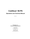
The complete amplitude frequency response of an 8th order Butterworth low
pass filter is shown in figure 4.1. The frequency is normalized to the cutoff
frequency fc.
A m p litu d e / d B
0
-2 0
-4 0
-6 0
-8 0
f
-1 0 0
0 .0 1
0 .0 2
0 .0 5
0 .1
0 .2
0 .5
1
2
5
fC
Figure 4.1: Amplitude frequency response of an 8th order Butterworth low pass filter
0DNLQJ0HDVXUHPHQWV
The amplitude error in the pass band caused by the filter can be determined
from figure 4.2.
A m p litu d e e r r o r / %
1
0
-1
-2
-3
-4
-5
-6
-7
-8
f
fC
-9
0
0 .1
0 .2
0 .3
0 .4
0 .5
0 .6
0 .7
0 .8
0 .9
Figure 4.2: Amplitude error of an 8th order Butterworth low pass filter
The phase frequency response of the filter is shown in figure 4.3.
p h a s e / d e g re e s
0
-5 0
-1 0 0
-1 5 0
-2 0 0
-2 5 0
-3 0 0
-3 5 0
-4 0 0
0
0 .2
0 .4
0 .6
0 .8
1
f
fC
Figure 4.3: Phase frequency response of an 8th order Butterworth low pass filter in the pass
band
0DNLQJ0HDVXUHPHQWV
369)8
In the PSV 300-F and -U low pass filters with 3rd order Bessel characteristics
and cutoff frequencies of 5 kHz, 20 kHz or 100 kHz are used. Characteristic for
Bessel filters is the phase linearity from the frequency zero up to the cutoff
frequency, i.e. the phase shift increases in proportion to the frequency. The
filter however, causes amplitude errors in the pass band which can be roughly
estimated:
Up to 20% of the cutoff frequency, the maximum amplitude error is ± 1%.
At the cutoff frequency, the amplitude error is − 3 dB (approx. − 30%).
The phase shift increases in proportion to the frequency from Zero degree at
the frequency Zero to approximately − 100 degrees at the cutoff frequency
(refer to figure 4.6). Due to this linear phase frequency response, the filter
shows optimal transmission behavior for pulses, as all frequencies of a
complex wave are subjected to the same time delay. Thus the shape of the
pulse is not falsified but it is merely delayed.
The complete amplitude frequency response of a 3rd order Bessel low pass
filter is shown in figure 4.4. The frequency is normalized to the cutoff
frequency fc.
A m p litu d e / d B
1 0
0
-1 0
-2 0
-3 0
-4 0
-5 0
f
-6 0
0 .1
0 .2
0 .5
1
2
5
1 0
2 0
fC
Figure 4.4: Amplitude frequency response of a 3rd order Bessel low pass filter
0DNLQJ0HDVXUHPHQWV
The amplitude error caused by the filter can be determined from figure 4.5.
A m p litu d e e r r o r / %
0
-5
-1 0
-1 5
-2 0
-2 5
f
-3 0
0 .0
0 .1
0 .2
0 .3
0 .4
0 .5
0 .6
0 .7
0 .8
0 .9
1 .0
fC
Figure 4.5: Amplitude error of a 3rd order Bessel low pass filter in the pass band
The phase frequency response of the filter is shown in figure 4.6.
P h a s e / d e g re e s
0
-2 0
-4 0
-6 0
-8 0
f
-1 0 0
0 .0
0 .2
0 .4
0 .6
0 .8
1 .0
fC
Figure 4.6: Phase frequency response of a 3rd order Bessel low pass filter in the pass band
0DNLQJ0HDVXUHPHQWV
3KDVHVKLIW
An additional time delay is caused by the velocity decoder. It depends on the
FDXVHGE\WKH measurement range and is approximately a few microseconds. The resulting
YHORFLW\
overall phase shift ∆Φ can be estimated using the following simple equation:
GHFRGHU
Equation 4.1
∆Φ = Φ LP + p s ⋅ f
ΦLP ... phase shift of the low pass filter, refer to figure 4.3 and figure 4.6
ps
... specific phase roll-off, refer to specifications in section 7.1.3
f
... frequency in kHz
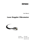
7UDFNLQJ)LOWHU
The tracking filter is used to improve the signal-to-noise ratio of the
interferometer signal. This is particularly good for bridging short dropouts
which occur due to the speckled natured of the light scattered back. The
bridging capability is generally better with a high time constant SLOW,
however, it may not be possible to follow highly dynamic signals any more. In
this case, FAST or OFF have to be selected. The best setting therefore has to
be determined from case to case or be estimated based on the range diagram
in figure 4.7. The range diagram shows the dynamic limits for both settings of
the tracking filter, plotted versus the frequency.
V e lo c ity / m / s
1 0
v e lo c ity lim it 3 m /s
3
F A
S T
1
a c
ce
le r
a
tio
n
lim
it
3 8
0 0
g
fr e q u e n c y lim it 1 0 0 k H z
0 .3
0 .1
0 .0 3
0 .0 1
0 .0 3
0 .1
0 .3
1
3
1 0
3 0
1 0 0
3 0 0
F re q u e n c y / k H z
Figure 4.7: Operating ranges of the tracking filter
A constant velocity limit of approximately 3 m / s is characteristic for the lower
frequency range. If the velocity exceeds this value, it means that the tracking
filter generally has to be switched OFF. In the medium frequency range, the
velocity limit changes over to become an acceleration limit, i.e. the velocity
limit decreases in inverse proportion to the frequency. In the upper frequency
range a constant velocity limit becomes effective again.
0DNLQJ0HDVXUHPHQWV
To set the tracking filter, the diagram in figure 4.7 can be summarized in the
following general rules:
For frequencies above 100 kHz as a general rule the tracking filter should
be switched off. In principle it can follow higher frequencies but in this
range amplitude errors of up to approximately 10% can occur due to
dynamic errors.
For medium velocities and frequencies, the acceleration limits of the
tracking filter have to be taken into consideration. The optimal setting
must be found with the diagram. If the velocity or acceleration limits are
exceeded, the tracking filter loses lock (refer to section C.2). This will
cause serious signal distortions, an example of which can be seen in
figure 4.8.
Figure 4.8: True velocity signal (top) and signal when the tracking filter loses lock (bottom)
The upper trace in figure 4.8 shows the sinusoidal velocity signal with the
tracking filter in position OFF. The lower trace shows the velocity signal
with the tracking filter in position SLOW. The tracking filter is on the limit of
the range where it loses lock, the signal is partly distorted.
mmmm--------In the measurement ranges 1 mm
s - ⁄ V , 5 --------s ⁄ V and 10 --------s ⁄ V , the tracking filter
should be set to SLOW as a general rule.
Using the velocity decoder PLL-DC the tracking filter is particularly
important. For technical reasons the PLL-DC is more sensitive to dropouts
than the decoder OVD-04. Thus the tracking filter should be set to SLOW
as long as the acceleration limit is not exceeded (refer to figure 4.7).
0DNLQJ0HDVXUHPHQWV
2SWLPDO6WDQGRII'LVWDQFHVIRUWKH6FDQQLQJ+HDG
The stand-off distance is measured from the front panel of the scanning head.
The optimal stand-off distances are:
14 mm + n ⋅ 203 mm,
n = 0; 1; 2; ...
i.e. at 14 mm; 217 mm; 420 mm; 623 mm; etc.
0D[LPDRI
YLVLELOLW\
The light source of the PSV is a helium neon laser. This is a multimode laser
in which a maximum of two modes can exist. The interference of the two
modes leads to the intensity of the resulting optical signal varying periodically
with the stand-off distance. The intensity increases to a maximum, i.e. a
maximum of visibility is present if the optical path difference is an evennumbered multiple of the length of the laser cavity (203 mm). As the optical
path difference is equal to twice the stand-off distance (the beam goes there
and back), a maximum of visibility is present once per laser cavity length.
In practice, it is not usually necessary to search for the maximum of visibility
as the PSV is sensitive enough to make a measurement even close to the
minimum. A minimum is indicated during the warm-up phase by periodic
fluctuation on the signal level display.
0DNLQJ0HDVXUHPHQWV
2SHUDWLQJWKH369
2SHUDWLQJWKH369
6ZLWFKLQJ2QDQG2II
&RQWUROOHU
The controller is switched on by turning the key switch on the front panel to
position I. The L ED POWER above the key switch lights up and shows that the
controller is ready to operate.
Is the PSV correctly cabled as described in section 3.4.2, the LED POWER on
the front of the junction box also lights up and shows that the junction box is
ready to operate. Also the LED LASER on the scanning head lights up and
shows that the scanning head is ready to operate and that the laser is active,
even if the beam shutter is closed (refer to section 5.2 and section 5.3).
:RUNVWDWLRQ
To switch on the workstation, set the main switch on the back to position I.
Then open the front flap using the key and push the black button.
%ORFNLQJWKH/DVHU%HDP
The scanning head is equipped with a beam shutter. This can be used to
block the laser beam without switching off the laser, thus keeping the system
in thermal equilibrium.
The rotary knob for the beam shutter is on the back of the scanning head and
is labeled EMISSION ON / OFF. To block the laser beam, turn the knob
clockwise until the red mark points at OFF.
:DUQLQJ 2QO\ switch the beam shutter to the ON position when you are making measurements!
:DUQLQJ To position the scanning head, switch the beam shutter to the OFF position. Only when the
head is roughly in place and has been fixed in a stable position, switch the beam shutter to
ON for precise adjustment.
,QGLFDWLQJ/DVHU$FWLYLW\
On the back of the scanning head the L ED LASER below the rotary knob of
the beam shutter indicates the laser activity. The LED is lit when the laser is
active (key switch on the front of the controller in position I). The LED is lit
regardless of whether the beam shutter is open or closed.
2SHUDWLQJWKH369
6HWWLQJXSWKH6FDQQLQJ+HDG
)OXLGVWDJH
If your PSV is equipped with a tripod and a fluid stage, you can manually
setup the scanning head using the three hand-grips as described in the
assembly instruction provided by the manufacturer MANFROTTO.
3DQWLOWVWDJH
RSWLRQDO
If your PSV is equipped with a heavy-duty tripod and a motorized pan-tilt
stage, it is easier to setup the scanning head. You control the pan-tilt stage
either with the software (refer to your software manual) or using the four
control keys on the front of the junction box.
The scanning head can be panned to the left and right by ± 90 degrees using
the control keys ← and →. It can be tilted upward and downward by ± 84°
using the control keys ↑ and ↓.
&DXWLRQ Avoid any additional weighting on the pan-tilt stage by placing objects on top of the
scanning head or attaching things to it ! This may put strain on the pan-tilt stage.
6WDQGRII
GLVWDQFH
Please pay also attention to the information on optimal stand-off distances for
the scanning head provided in section 4.3.
'XVW&RYHURQWKH6FDQQLQJ+HDG
The scanning head is equipped with a dust cover to protect the scanner
mirrors and the front lens of the video camera when you are not making
measurements.
The dust cover is closed by rotating the switch bar on the front of the scanning
head into vertical position.
&DXWLRQ To protect the lenses and scanner mirrors, RQO\ open the dust cover when your are making
measurements !
2SHUDWLQJWKH369
)RFXVLQJWKH/DVHU%HDP
+DQGVHW
369=
The hand set PSV-Z-051 is connected to the circular jack REMOTE
CONTROL on the front of the scanning head. You can focus the laser beam
using the emphasized part of the hand set shown in figure 5.1.
P S V -Z -0 5 1
F A R
N E A R
T E A C H
H O M E
D E L
M O D E
G R ID
F R E E
Figure 5.1: Focusing the laser beam using the hand set PSV-Z-051
1RWH 1HYHU use the hand set PSV-Z-051 together with the optional hand set OFV-310 (refer to
section A.3) !
Using the two arrow keys FAR and NEAR, the laser beam is focused as
follows:
Focusing on infinity:
key ↑ FAR
Focusing close-up:
key ↓ NEAR
If you press the keys for more than approximately one second, the motor
switches over to fast mode. For fine positioning, the keys can be repeatedly
pressed briefly. At the end of the adjustment range, the motor stops
automatically and the respective L ED FAR or NEAR lights up.
Beside the keys for focusing, there is a signal level display which helps you to
optimize the focus. The signal shown is identical to that on the scanning head
and on the display of the controller.
2SHUDWLQJWKH369
6RIWZDUH
When the PSV is controlled via the software (L EDs REMOTE and LLO are lit
up), you can use the software to focus the laser beam, please refer to your
software manual.
&RQWUROOHU
When the controller is operated without the software, you can focus the laser
beam via the menu FOCUS (refer to section 5.12.3).
+DQGVHW
2)9
RSWLRQDO
To focus the laser beam, you can also use the optional hand set OFV-310
instead of the hand set PSV-Z-051 (refer to section A.3).
2SWLPL]LQJWKH)RFXVRIWKH/DVHU%HDP
The signal level display helps you to optimize the focus of the laser beam.
The signal level is shown as a bar display:
on the back of the scanning head
on the display of the controller
in the software (refer to your software manual)
on the hand set PSV-Z-051 (refer to section 5.6)
on the optional hand set OFV-310 (refer to section A.3).
2SHUDWLQJWKH369
3RVLWLRQLQJWKH/DVHU%HDP
+DQGVHW
369=
The hand set PSV-Z-051 is connected to the circular jack REMOTE
CONTROL on the front of the scanning head. You can position the laser beam
using the clearly visible part of the hand set shown in figure 5.2. To do so,
proceed as follows:
1. Switch on the workstation and start the PSV software.
2. Change to the Acquisition Mode as described in your software manual.
P S V -Z -0 5 1
F A R
N E A R
T E A C H
H O M E
D E L
M O D E
G R ID
F R E E
Figure 5.2: Positioning the laser beam using the hand set PSV-Z-051
3. Press the MODE key on the hand set to select the kind of movement.
7KHODVHUEHDPFDQEHSRVLWLRQHGLQWKH*5,'PRGHRULQWKH)5((
PRGH
*5,'PRGH/('*5,'LVOLWXS
You move the laser beam on already defined scan points using the arrow
keys. The order in which the software approaches the scan points is
determined by an internal algorithm. Using the keys → or ↑, you move the
laser beam forwards along the scan points and backwards using the keys ←
or ↓. If you press the HOME key, the laser beam is positioned on the first scan
point.
1RWH The longer you hold the arrow key pressed, the faster the laser beam moves !
2SHUDWLQJWKH369
)5((PRGH/(')5((LVOLWXS
You move the laser beam freely using the arrow keys. To do so, press the
arrow key for the direction you require. If you press the HOME key, then the
laser beam is positioned so that it is emitted from the scanning head
perpendicular to the front panel (position (0;0), is indicated in the software).
6RIWZDUH
When the PSV is controlled via the software (L EDs REMOTE and LLO are lit
up), you can use the software to position the laser beam, please refer to your
software manual.
2SHUDWLQJWKH369
'HILQLQJDQG'HOHWLQJ6FDQ3RLQWV$36
1RWH Defining and deleting individual scan points is only available if you have the software option
APS Professional (PSV-Z-062) !
+DQGVHW
369=
The hand set PSV-Z-051 is connected to the circular jack REMOTE
CONTROL on the front of the scanning head. You can define and delete
individual scan points using the clearly visible part of the hand set shown in
figure 5.3. To do so, proceed as follows:
1. Switch on the workstation and start the PSV software.
2. Change to the Acquisition Mode then to Define Scan Points and select the
Point Mode as described in your software manual.
To define scan points, select the FREE mode using the MODE key on the
hand set (LED FREE is lit up).
P S V -Z -0 5 1
F A R
N E A R
T E A C H
H O M E
D E L
M O D E
G R ID
F R E E
Figure 5.3: Defining and deleting scan points using the hand set PSV-Z-051
3. Using the four arrow keys, move the laser beam to the desired position.
4. Press the TEACH button and the scan point is defined.
7KHQHZO\GHILQHGVFDQSRLQWLVVKRZQLQWKHVRIWZDUH
2SHUDWLQJWKH369
5. Repeat steps 3 and 4 until all desired scan points are defined.
1RWH To get a 3D view style of the data, you have to define connections in the software. Please
refer to your software manual.
To delete defined scan points, select the GRID mode using the MODE key on
the hand set (L ED GRID is lit up). The TEACH key now functions as DEL key
(for deleting).
6. Using the arrow keys, move the laser beam forwards or backwards to the
scan point you want to delete.
7. Press the DEL key and the selected scan point is deleted.
8. Repeat steps 6 and 7 until all desired scan points are deleted.
1RWH If you press the DEL key for more than approximately one second, the scan points will be
deleted one after the other !
6RIWZDUH
When the PSV is controlled via the software (L EDs REMOTE and LLO are lit
up), you can use the software to define and delete scan points, please refer to
your software manual.
6HWWLQJV
6RIWZDUH
When the PSV is controlled via the software (L EDs REMOTE and LLO are lit
up), all settings are adjusted via the software, refer to your software manual.
In this case the keys FUNCTION and SETTING on the front of the controller
do not have a function.
You will find information on setting the measurement range and the filters in
section 4.2.
&RQWUROOHU
When the controller is operated without the software, you can set the
measurement range and the filters via a menu on its display using the keys
FUNCTION and SETTING (refer to section 5.12).
2YHUUDQJH,QGLFDWRU
6RIWZDUH
Overranging is indicated in the software. Please refer to your software
manual.
&RQWUROOHU
If the LED OVER on the front of the controller is lit up continuously, it means
that the measurement range set is being exceeded. In this case the next
highest measurement range must be selected. You will find further information
on setting the measurement range in section 4.2.1.
2SHUDWLQJWKH369
2SHUDWLQJWKH&RQWUROOHUZLWKRXWWKH6RIWZDUH
2SHUDWLQJ3KLORVRSK\
In normal operation the keys FUNCTION and SETTING on the controller are
deactivated and all settings are adjusted via the software. It is also possible to
make measurements without using the workstation. In this case you can only
make single-point measurements and you can not make use of the digital data
processing of the PSV. The velocity signal is then available at the BNC jack
VELOCITY OUTPUT on the front of the controller.
The controller is operated via a menu on its display using the keys
FUNCTION and SETTING. The operating structure is mainly self-explanatory.
The individual menus are described in section 5.12.3.
)81&7,21 Using the keys ↑ and ↓ a menu is selected and within the menu
a parameter is selected.
6(77,1*
Settings are changed using the keys + and −.
The menu SETTINGS is shown in figure 5.4 as an example of the display.
Focus ↑
⇒ Tracking Filter
Fast
Velocity Decoder
HF
Velocity Range
125 mm/s/V
Velocity Filter
off (1.5 MHz)
Signal
Config ↓
Figure 5.4: Example of the controller’s display
The parameters are run through vertically on the display using the keys ↑
and ↓. Once the end of the display page is reached, it changes to the next
menu. The possibility of branching off to other menus is shown at the top and
the bottom on the right.
The cursor ⇒ on the left marks a selected parameter. The setting of the
parameter is changed to higher and lower values with the keys + and −.
Adjusted settings are activated straight away.
As the control processor has a battery supported memory, the settings are
stored when the instrument is switched off and reloaded when it is switched
on again or after RESET. This saves time making adjustments for repeated
measurements.
2SHUDWLQJWKH369
2UJDQL]DWLRQRIWKH0HQXV
The organization of the menus is shown in figure 5.5.
S E T T IN G S
IN T R O
F O C U S
C O N F IG
Figure 5.5: Organization of the controller’s menus. Menu FOCUS is optional.
The menus are organized as follows:
,1752
The start menu appears after switching on the controller or
after RESET.
6(77,1*6
This is the most important menu in which all settings for a
measurement in stand-alone operation are made i.e. the
measurement ranges and the filters are selected. It also
displays the signal level.
&21),*
This menu provides information on the configuration of the
controller i.e. the decoders and interfaces installed. The
interfaces can be configured in this menu.
)2&86
The laser beam can be focused in this menu. It also displays
the signal level.
2SHUDWLQJWKH369
7KH,QGLYLGXDO0HQXV
0HQX,1752
After being switched on or RESET, the controller shows that it is ready to
operate with the menu INTRO. It is not possible to change back to this menu
as it does not have a control function.
0HQX&21),* This menu provides information on the decoders and interfaces installed. The
individual configurations are described in the following.
9HORFLW\'HFRGHU
This line shows the velocity decoders installed and the number of available
velocity measurement ranges. The following abbreviations are used for the
individual decoders:
Table 5.1: Abbreviations of the individual velocity decoders
$EEUHYLDWLRQ
'HFRGHU
DC
PLL-DC
HF
OVD-04
Example:
3DC + 4HF means that the velocity decoder PLL-DC with 3 measurement
ranges and the velocity decoder OVD-04 with 4 measurement ranges are
installed.
,(((%XV,QWHUIDFH
When operating the controller via the IEEE-488 / GPIB interface on the back in
this line the instrument address can be set in the range .
1RWH If you control the PSV using the software via the IEEE-488 / GPIB interface, the
IEEE-488 / GPIB address of the controller must be set to !
6HULDO,QWHUIDFH
When operating the controller via the RS-232 interface on the back in this line
it is possible to switch between the transfer rates %DXG and %DXG.
1RWH For all PSV models, here the transfer rate must be set to %DXG !
2SHUDWLQJWKH369
0HQX
6(77,1*6
In the menu SETTINGS the measurement ranges and filters are set. The
contents of the menu depends on the decoders installed. The individual
settings have the following meaning.
7UDFNLQJ)LOWHU
In this line you can set the tracking filter. The input signal is pre-processed
with the tracking filter. You will find information on the settings 2)) / 6/2: /
)$67 of the tracking filter in section 4.2.3.
9HORFLW\'HFRGHU
In this line you can set the active velocity decoder. This line is only present if
both decoders OVD-04 and PLL-DC are installed. The velocity decoders are
abbreviated as described above in table 5.1.
1RWH mm
⁄
If the DC decoder is selected and the velocity measurement range 1 --------s - V is set, it is not
possible to change to the HF decoder because the HF decoder does not have this velocity
measurement range available.
9HORFLW\5DQJH
In this line you can set the velocity measurement range. The possible settings
depend on the velocity decoder selected. You will find information on setting
the velocity measurement range in section 4.2.1.
9HORFLW\)LOWHU
In this line you can set the cutoff frequency of the low pass filter. The possible
settings depend on the PSV model. In position OFF, the upper frequency limit
of the active velocity decoder is shown. You will find information on setting the
low pass filter in section 4.2.2.
6LJQDO
This line shows the optical signal level as a bar display.
0HQX)2&86
In this menu, the laser beam is focused using the − and + keys. The
movement of the motor to position the front lens is shown on the display of the
controller with following symbols:
< and >
Motor is running slowly
<< and >>
Motor is running quickly
|<< and >>|
Motor has stopped at the end of the adjustment range
The bar in the lower line of the display shows the optical signal level.
)DXOW'LDJQRVLV
)DXOW'LDJQRVLV
Simple tests are described in the following which you can carry out yourself in
the case of malfunction. In the case of more difficult faults in individual
functions, please contact our service personnel. The tests described here are
not meant to lead you to carry out maintenance work yourself but to provide
our service personnel with information which is as accurate as possible.
Testing the PSV is limited to such tests in which the housing does not have to
be opened. Opening the housing without authorization invalidates the
warranty.
If required, please contact our service department. Based on your fault
description, further procedure will be determined.
If the PSV has to be sent back for repair, please use the original packaging
and enclose an exact description of the fault.
*HQHUDO7HVWV
If any system component of the PSV does not function properly, please first
check the following:
1. Is the PSV correctly cabled as described in section 3.4.2 ?
2. Are there only original RS-232 cables from Polytec used (1:1 wired) ?
3. Is the transfer rate set to 9 600 Baud (refer to section 5.12.3) ?
4. If you control the PSV using the software via the IEEE-488 / GPIB
interface: Is the IEEE-488 / GPIB address of the controller set to 5 (refer to
section 5.12.3) ?
Check whether the data acquisition board is correctly installed. To do so,
proceed as follows:
5. Double-click the icon Measurement&Automation on the desktop.
6. Change into the folder Devices and Interfaces.
7KHGDWDDFTXLVLWLRQERDUGLVFRUUHFWO\LQVWDOOHGLILQWKHIROGHU3&,
RU3&,RU3&,LVOLVWHG,IQRWSOHDVHFKHFNZKHWKHUWKHGDWD
DFTXLVLWLRQERDUGLVSURSHUO\LQVHUWHGLQWRLWVVORWLQWKHZRUNVWDWLRQ
)DXOW'LDJQRVLV
1R/DVHU%HDP
If no laser beam is emitted, check the following:
1. Is the PSV correctly cabled as described in section 3.4.2 ?
2. Is the key switch on the front of the controller in position I ?
3. Is the dust cover on the front of the scanning head open (switch bar in
horizontal position) ?
4. Is the beam shutter on the back of scanning head in position ON ?
5. Is the LED LASER on the back of the scanning head lit up ?
:DUQLQJ $OZD\V disconnect from the mains EHIRUH checking the fuses !
,IWKH/('LVQRWOLWXSLWFDQEHDVVXPHGWKDWWKHUHLVDIDXOWZLWKWKH
SRZHUVXSSO\RIWKHFRQWUROOHU,QWKLVFDVHGLVFRQQHFWWKHPDLQVSOXJ
DQGFKHFNWKHIXVHVRQWKHEDFNSDQHO3OHDVHQRWHWKDWWKHUHDUHWZR
DFWLYHIXVHVZKLFKFDQERWKOHDGWRIDLOXUH
6. Is the LED POWER on the front of the junction box lit up ?
:DUQLQJ $OZD\V disconnect from the mains EHIRUH checking the fuses !
,IWKH/('LVQRWOLWXSLWFDQEHDVVXPHGWKDWWKHUHLVDIDXOWZLWKWKH
SRZHUVXSSO\RIWKHMXQFWLRQER[,QWKLVFDVHGLVFRQQHFWWKHPDLQVSOXJ
DQGFKHFNWKHIXVHVRQWKHEDFNSDQHO3OHDVHQRWHWKDWWKHUHDUHWZR
DFWLYHIXVHVZKLFKFDQERWKOHDGWRIDLOXUH
)DXOW'LDJQRVLV
1R9HORFLW\6LJQDO
If the laser beam is emitted but there is no velocity signal, check the following:
1. Is the PSV correctly cabled as described in section 3.4.2 ?
2. Put a matt white test surface such as a piece of paper at approximately
20 cm from the front panel of the scanning head in the beam path. Does
the signal level display react ?
,IWKHVLJQDOOHYHOGLVSOD\GRHVQRWUHDFWWKHLQSXWVHFWLRQRIWKH
FRQWUROOHULVIDXOW\
'DWD
DFTXLVLWLRQ
Check the correct function of the data acquisition board and the software as
follows:
3. Disconnect the BNC cable for the velocity signal from the BNC jack VELO
on the front of the junction box.
4. Feed the signal of a function generator to this BNC jack.
5. Display the time signal in an analyzer as described in your software
manual.
7KHGDWDDFTXLVLWLRQERDUGDQGWKHVRIWZDUHZRUNSURSHUO\LIWKHVLJQDO
RIWKHIXQFWLRQJHQHUDWRULVGLVSOD\HGFRUUHFWO\,QWKLVFDVHWKHUHLVD
SUREOHPLQWKHFRQWUROOHU
2XWSXWVLJQDO
Now check the output signal of the controller as follows:
6. Re-connect the velocity signal to the BNC jack VELO on the front of the
junction box.
7. Display the time signal in an analyzer as described in your software
manual.
mm8. Set the measurement range to 10 --------s ⁄ V . Does the output signal react to
the test surface moving ?
9. If the output signal does not react, check whether a significant DC offset is
present.
1RUPDOO\D'&YROWDJHRIOHVVWKDQ P9LVPHDVXUHG
10. Block the laser beam. Is the output signal noisy or is a straight line
shown ?
1RLVHPXVWRFFXUZKHQWKHODVHUEHDPLVEORFNHG
)DXOW'LDJQRVLV
7HFKQLFDO6SHFLILFDWLRQV
7HFKQLFDO6SHFLILFDWLRQV
&RQWUROOHU2)9 6
*HQHUDO'DWD
Mains voltage:
100 / 115 / 230 VAC ± 10%, 50 / 60 Hz,
adjustable on the back panel
Power consumption:
max. 150 VA
Fuses:
1.0 A / slow-blow for 230 V
2.0 A / slow-blow for 100 / 115 V
Protection class:
I (protective grounding)
Operating temperature:
+ 5°C... + 40°C (41°F... 104°F)
Storage temperature:
− 10°C ... + 65°C (14°F... 149°F)
Relative humidity:
max. 80%, non-condensing
Dimensions:
450 mm × 355 mm × 135 mm
Weight:
10.8 kg
Calibration recommended:
every 2 years
/RZ3DVV)LOWHU
369+
(for typ. amplitude and phase frequency response refer to section 4.2.2)
Filter type:
Butterworth 8th order
Cutoff frequencies:
400 Hz ... 102.4 kHz, adjustable in steps of 400 Hz
Frequency roll-off:
− 160 dB/ dec = − 48 dB/ oct
Stop band rejection:
> 80 dB
369)8
(for typ. amplitude and phase frequency response refer to section 4.2.2)
Filter type:
Bessel 3rd order
Cutoff frequencies:
5 kHz, 20 kHz, 100 kHz, adjustable
Frequency roll-off:
− 60 dB / dec = − 18 dB/ oct
Stop band rejection:
> 70 dB
7HFKQLFDO6SHFLILFDWLRQV
6LJQDO9ROWDJH2XWSXW9(/2&,7<287387
*HQHUDO'DWD
Output swing:
± 10 V
Output impedance:
50 Ω
Minimum load resistance:
10 kΩ (− 0.5% additional error)
Overrange indicator threshold: typ. 95% of full scale
Velocity decoder PLL-DC: ± 50 mV
Maximum DC-offset:
Velocity decoder OVD-04: ± 20 mV
0HDVXUHPHQW5DQJHV
Velocity
decoder
Measurement
range
OVD-04
Resolution
(scaling factor) (peak-peak)
mm
--------s-
PLL-DC
Full scale
output
⁄V
mm
--------s-
1
Maximum
frequency 2
Maximum
acceleration
-H, -U
-F
-H, -U
-F
µm
-------s
kHz
kHz
g
g
1
20
0.3
20
20
150
150
5
100
0.3
50
50
1 600
1 600
25
500
0.8
50
50
8 000
8 000
10
200
0.5
200
200
12 000
12 000
25
500
2
250
1 000
40 000
160 000
125
2,500
5
250
1 500
200 000
1 200 000
1 000
20 000
10
250
1 500
1 600 000
9 600 000
1
Resolution is defined as the signal amplitude (rms) at which the signal-to-noise ratio is 0 dB in a 10 Hz spectral bandwidth
(RBW), measured at 3M Scotchlite Tape.
2
− 1 dB maximum error
&DOLEUDWLRQ$FFXUDF\
Velocity
decoder
Measurement
range
@ T = (25 ± 5) °C
(T = (77 ± 9)°F)
full operating
temperature range
% of rms reading
% of rms reading
± 1.0
± 1.2
10
± 1.0
± 1.5
25
± 1.0
± 2.0
125
± 1.5
± 2.5
1 000
± 1.5
± 2.5
mm
--------s-
PLL-DC
Amplitude error
⁄V
1
5
25
OVD-04
Conditions: sinusoidal vibration, f = 1 kHz, amplitude 70% of full scale range,
load resistance ≥ 1 MΩ
7HFKQLFDO6SHFLILFDWLRQV
$PSOLWXGH/LQHDULW\
± 1% of rms. reading (one particular range)
Maximum linearity error:
± 2.5% of rms. reading (overall)
Linearity error is defined as the amplitude-dependent, relative deviation of the scaling
factor referred to the nominal scaling factor under calibration conditions.
$PSOLWXGH)UHTXHQF\5HVSRQVH)ODWQHVV
Velocity
decoder
Measurement range
PLL-DC 1
1
0 Hz 15 kHz -
15 kHz : ± 0.1 dB
20 kHz : + 0.1 dB/ − 0.25 dB
5 and 25
0 Hz 20 kHz -
20 kHz : ± 0.1 dB
50 kHz : ± 0.2 dB
mm--------s
Max. additional error referred to f = 1 kHz
⁄V
10
0.5 Hz - 10 Hz :
10 Hz - 20 kHz :
20 kHz - 100 kHz :
100 kHz - 200 kHz :
± 0.5 dB
± 0.05 dB
+ 0.05 dB/ − 0.2 dB
+ 0.05 dB/ − 1 dB
25, 125 and 1 000
0.5 Hz - 10 Hz :
10 Hz - 20 kHz :
20 kHz - 100 kHz :
100 kHz - 200 kHz :
1 MHz :
200 kHz -
± 0.5 dB
± 0.05 dB
± 0.15 dB
± 0.3 dB
± 0.8 dB 2
OVD-04
1
The measurement ranges of this decoder can be used from the frequency 0 Hz (full DC capability).
2
PSV 300-F only
3KDVH)UHTXHQF\5HVSRQVH
With the low pass filter switched off, the velocity decoder behaves as a system of
constant time delay up to approximately 60% of the maximum frequency of the
measurement range set, i.e. the phase shift is proportional to the frequency. The
phase shift depends, however, on the range settings.
Velocity
decoder
Measurement
range
OVD-04
Specific phase roll-off ps
(typ.)
-H, -U
-F
-H, -U
-F
⁄V
µs
µs
° / kHz
° / kHz
1
24
24
− 8.6
− 8.6
5
7.1
7.1
− 2.6
− 2.6
25
6.0
6.0
− 2.2
− 2.2
10
6.1
6.1
− 2.2
− 2.2
25
5.5
1.9
− 2.0
− 0.7
125
5.5
1.9
− 1.9
− 0.7
1 000
3.5
0.9
− 1.3
− 0.33
mm
--------s-
PLL-DC
Time delay (typ.)
7HFKQLFDO6SHFLILFDWLRQV
+DUPRQLF'LVWRUWLRQV
Measurement range
mm--------s
⁄V
THD @ f = 1 kHz
up to 70% of full scale range
up to full scale
1, 5, 10 and 25
< 0.2% (< − 54 dB)
< 0.3% (< − 50 dB)
125 and 1 000
< 0.3% (< − 50 dB)
< 0.5% (< − 46 dB)
,QWHUIDFHV
RS-232:
8 data bits, no parity, baud rate 4 800 or 9 600
9-pin female Sub-D cable to the workstation,
1 : 1 wired
IEEE-488 / GPIB:
according to IEEE-488.1
REMOTE FOCUS:
special interface for the optional hand set OFV-310
EXT.DEC.:
special interface for an external digital displacement
decoder
SIGNAL:
0 V... 3 V DC, proportional to the logarithm of the
optical signal level, load resistance ≥ 10 kΩ
7HFKQLFDO6SHFLILFDWLRQV
-XQFWLRQ%R[369=
*HQHUDO'DWD
Mains voltage:
100 ... 240 VAC ± 10%, 50 / 60 Hz
Power consumption:
max. 75 VA
Fuses:
2.0 A / slow-blow
Protection class:
I (protective grounding)
Operating temperature:
+ 5°C... + 40°C (41°F... 104°F)
Storage temperature:
− 10°C ... + 60°C (49°F... 149°F)
Relative humidity:
max. 80%, non-condensing
Dimensions:
450 mm × 355 mm × 90 mm
Weight:
5.8 kg
,QWHUIDFHV
56
Baud rate:
9 600 Baud
Data format:
8 data bits, 1 stop bit, no parity bit
Cable:
9-pin female Sub-D cable, 1 : 1 wired
Pins:
pin 2:
received data Red (←)
pin 3:
transmitted data Axed (→)
pin 5:
reference potential GND
pin 1; 4; 6; 7; 8; 9: N / A
9(/25()5() 5()DW0RGHO+
Input impedance:
1 MΩ in parallel with 100 pF
Input coupling:
AC / DC, adjustable in the software
AC − 3 dB cutoff frequency: 3.4 Hz
Over voltage protection:
± 42 V
75,*,1
Compatibility:
TTL
Input voltage:
max. + 5.5 V
Input current:
max. 1 mA
*$7(,1
Compatibility:
TTL
Input voltage:
max. + 7.0 V
7HFKQLFDO6SHFLILFDWLRQV
287 287 287 2QO\0RGHO+
Output voltage swing:
max. ± 10 V referred to GND
Output current:
max. ± 5 mA
Output impedance:
< 0.1Ω
Short circuit protection:
permanently short circuit proof
Load resistance:
min. 2kΩ
Load capacity:
unlimited
6,*1$/2QO\0RGHO)8
Output voltage swing:
max. ± 10 V referred to GND
Output current:
max. ± 5 mA
Output impedance:
50 Ω
Short circuit protection:
permanently short circuit proof
Load resistance:
min. 2 kΩ
Load capacity:
unlimited
6<1&6<1&287DW0RGHO+
Compatibility:
TTL
Output HIGH voltage:
min. 4.35 V (Iout = 3.5 mA)
Output LOW voltage:
max. 0.4 V (Iout = 5 mA)
$8;287
Compatibility:
TTL
Output HIGH voltage:
min. 2.4 V (Iout = 15 mA)
Output LOW voltage:
max. 0.5 V (Iout = 64 mA)
$8;,12QO\0RGHO)8
Compatibility:
TTL
Input voltage:
max. + 7.0 V
7HFKQLFDO6SHFLILFDWLRQV
6FDQQLQJ+HDG2)9
*HQHUDO'DWD
Laser type:
helium neon
Wavelength:
633 nm
Cavity length:
203 mm
Laser class:
II
Laser output power:
< 1 mW
Power consumption:
ca. 15 W
Operating temperature:
+ 5°C... + 40°C (41°F... 104°F)
Storage temperature:
− 10°C ... + 65°C (14°F... 149°F)
Relative humidity:
max. 80 %, non-condensing
Dimensions:
refer to section 7.3.5
Weight:
11 kg
2SWLFV
Long range
(QR)
Mid range
(MR)
mm
100
60
mm
450
175
Aperture diameter (1 / e )
mm
12
7
Spot size (typ.)
µm
Front lens1
Focal length
Minimum stand-off distance
2
@
175 mm
-
10
@
450 mm
15
33
@
1 000 mm
42
79
50
84
@ each additional meter plus
Maxima of visibility 2
mm
14 + n ⋅ 203, n = 0; 1; 2;...
1
A label shows the front lens model which is fitted. The label can be seen through the top
left air vents of the scanning head (refer to figure 7.1).
2
Measured from the front panel of the scanning head
L a b e l
Q R o r M R
in s id e
Figure 7.1: Position of the label for the front lens model
7HFKQLFDO6SHFLILFDWLRQV
6FDQQHU
Type:
servo-controlled galvo motor
Maximum deflection
horizontal: ± 20°
vertical: ± 20°
Angular resolution:
<0.002°
Pointing stability:
<0.01° / hour (after warming-up)
9LGHR&DPHUD
Video system:
CCIR/ PAL
Sensor:
color CCD 1 / 4”, 752 x582 pixels
Signal-to-noise ratio:
>50 dB
Zoom:
72 x (4 x digital zoom)
Lens:
F 1.4 / f = 4.1 ... 73 mm, auto focus, auto iris
18-fold motor-driven zoom
Angle of view (horizontal):
> 48° ... 2.7°
Minimum stand-off distance:
@ wide end:
10 mm
@ tele end:
800 mm
Minimum illumination:
3 lux
7HFKQLFDO6SHFLILFDWLRQV
'LPHQVLRQV
1 5 0 .5 0
B e a m
B e a m
8 0
a x is fo r
x - m o tio n
3 1 .7 1
1 2 .5 0
0
1 3
+ 0 .0 2 8
- 0 .0 1 0
4
Æ
1 3 4 .5 0
5 (3 x )
2 0 7 .5 0
2 3 .4 0
2 1 3 .5 0
M
4 3 0
M
6
1 3 6 ± 0 .0 1
M
1 7 8
1 0 1 .6 0
1 4 9 .2 0
6
Æ
4
+ 0 .0 2 8
- 0 .0 1 0
T h e c o n n
a p p ro x . 1 2 0
a t th e b a c
s c a n n
1 7 0
e c
m
k
in
to r r e q u ir e s
m fre e s p a c e
p a n e l o f th e
g h e a d .
1 2 0
4 0 5
1 3 0
1 8 8
8 8 .3 1
4 3
3 3 .8 1
a x is fo r
x - m o tio n
8 0
a x is fo r
y - m o tio n
1 5 2 .6 2
Figure 7.2: Views of the scanning head OFV-056
7HFKQLFDO6SHFLILFDWLRQV
:RUNVWDWLRQ3693&
,QGXVWULDO:RUNVWDWLRQ
Mains voltage:
workstation with voltage selector:
115 / 230 VAC, 50 / 60 Hz, adjustable on the back panel
workstation with wide range input:
100 ... 240 V, 50 / 60 Hz
Power consumption:
max. 350 VA
Processor:
min. Pentium III, 700 MHz
Hard disk drive (HDD):
> 18 GB
Operating system:
Microsoft Windows2000
Network board:
Ethernet card
CD drive / writer:
refer to user manual of the drive manufacturer
Housing:
industrial PC housing
'HVNWRS3&
Mains voltage:
workstation with voltage selector:
115 / 230 VAC, 50 / 60 Hz, adjustable on the back panel
workstation with wide range input:
100 ... 240 V, 50 / 60 Hz
Power consumption:
max. 350 VA
Processor:
min. Pentium III, 700 MHz
Hard disk drive (HDD):
> 18 GB
Operating system:
Microsoft Windows2000 or WindowsXP
Network board:
Ethernet card
CD drive / writer:
refer to user manual of the drive manufacturer
Housing:
desktop PC housing
'DWD$FTXLVLWLRQ
369+
369)
3698
PCI-4452
PCI-6111
PCI-4451
4
2
2
16 bit
12 ... 16 bit effectively
(depending on the
bandwidth)
16 bit
Maximum bandwidth
80 kHz
1 MHz
40 kHz
Maximum number of
FFT lines
6 400
optional 12 800
6 400
optional 12 800
3 200
optional 6 400
PSV-Model
Data acquisition board
Input channels
simultaneously
Resolution
For further information, please refer to the manual of the data acquisition board which
is installed on the workstation. Switch on the workstation and in the Start menu of the
task bar, select Programs > National Instruments > NI-DAQ > Documents. There click
on the corresponding manual for the data acquisition board of your PSV model.
7HFKQLFDO6SHFLILFDWLRQV
0RWRUL]HG3DQ7LOW6WDJH369=RSWLRQDO
Mains voltage:
115 / 230 VAC, 50 / 60 Hz,
adjustable on the connector box
Power consumption:
max. 30 W
Operating temperature:
− 20°C ... + 50°C (− 4°F... 122°F)
Relative humidity:
max. 95 %, non-condensing
Maximum angle of rotation:
pan (horizontal): ± 90°
tilt (vertical): ± 84° (limited by limit switch)
Rotation velocity:
horizontal: 6° /sec.
vertical: 5° / sec.
Backlash:
± 0.5° (testing moment 10 Nm)
Dimensions:
top mount: 276 mm × 149 mm × 286 mm
Weight:
12 kg
Max. load:
18 kg
7HFKQLFDO6SHFLILFDWLRQV
$2SWLRQDO$FFHVVRULHVIRUWKH6FDQQLQJ+HDG2)9
$SSHQGL[$2SWLRQDO$FFHVVRULHVIRUWKH6FDQQLQJ+HDG2)9
$&RD[LDO8QLWDQG$FFHVVRULHV
$&ORVH8S8QLW2)9&)RU2)9&)
You can scan small objects at short distance using the close-up unit shown in
figure A.1. Thereby the beam path of the laser is overlaid to the video image
to equalize the parallax error.
Figure A.1: Close-up unit OFV-056-C
To ensure a clearly visible laser spot on the video image, only a small part of
the laser light is used for the video camera. The size of that part depends on
the back scattering properties of the surface. Two models of the close-up unit
are available which have different special coated beam splitters:
2)9&) for mat surfaces
(reduces the intensity of the laser light by 97%)
2)9&) for highly reflective surfaces
(reduces the intensity of the laser light by 99.8%)
7HFKQLFDO6SHFLILFDWLRQV
Max. scan angle in x-direction: ± 5°
Max. scan angle in y-direction: ± 4°
Dimensions:
135 mm x 90 mm x 100 mm and figure A.2
Weight:
1.3 kg
%ORFN)LOWHU2)9)
If the intensity of the laser light is still too high the supplied helium neon block
filter should be additionally mounted. The block filter is screwed directly to the
the camera aperture of the scanning head and reduces once more the
intensity of the laser light back scattered to the video camera by 98%.
$
$2SWLRQDO$FFHVVRULHVIRUWKH6FDQQLQJ+HDG2)9
&ORVH8S/HQVHV
Together with the close-up unit a set of close-up lenses with different focal
distances (1, 2 and 4 diopters) is delivered. A maximum of two close-up
lenses or one close-up lens and the block filter can be mounted. The close-up
lenses are also screwed directly to the camera aperture of the scanning head
before mounting the close-up unit. The stand-off distances and the scan fields
of the close-up lenses and of combinations of the lenses are shown in
table A.1.
Table A.1: Stand-off distances and scan fields of the close-up lenses
Lens or
combination
Stand-off
distance 1
Min.
scan field
(X x Y)
Nom.
scan field 2
(X x Y)
Max.
scan field
(X x Y)
Spot
diameter 3
Diopters
mm
mm
mm
mm
µm
2
320 ... 450
5x4
20 x 16
70 x 55
40
2+1
250 ... 350
4x3
16 x 8
60 x 45
30
4
200 ... 260
3 x 2.4
12 x 10
50 x 40
25
4+1
175 ... 215
2.5 x 2
10 x 8
45 x 34
20
4+2
152 ... 175
2 x 1.6
8 x 6.4
40 x 30
15
1
measured from the front panel of the scanning head
2
at 18 x optical zoom
3
with front lens model MR
0RXQWLQJWKH&ORVH8S8QLW
For transportation the close-up unit is secured on the back with a transparent
perspex plate. For mounting the close-up unit, you proceed as follows:
1. Before mounting, undo the perspex plate and keep it in a safe place.
2. If required first screw the close-up lenses or the block filter to the camera
aperture.
3. Fix the close-up unit on the front of the scanning head using the two
knurled screws.
&DXWLRQ Pay attention to the correct fit of the precision pins and RQO\ hand-tighten the knurled
screws !
$
$2SWLRQDO$FFHVVRULHVIRUWKH6FDQQLQJ+HDG2)9
'LPHQVLRQV
B e a m
1 5 0 .5 0
B e a m
4 9
9 4
8 0
9 7 .9 0
a x is fo r
x - m o tio n
3 1 .7 1
1 2 .5 0
0
1 3
+ 0 .0 2 8
- 0 .0 1 0
4
Æ
1 3 4 .5 0
M
5 1 1
6
5 (3 x )
2 0 7 .5 0
2 1 3 .5 0
2 3 .4 0
M
1 3 6 ± 0 .0 1
M
1 7 8
1 0 1 .6 0
1 4 9 .2 0
6
Æ
4
+ 0 .0 2 8
- 0 .0 1 0
1 7 0
T h e c o
a p p ro x . 1
a t th e b
s c a
n n
2 0
a c
n n
e c
m
k
in
to
m
p a
g
r r e q u ir e s
fre e s p a c e
n e l o f th e
h e a d .
1 2 0
4 0 5
1 3 0
1 8 8
a x is fo r
x - m o tio n
8 8 .3 1
3 3 .8 1
a x is fo r
y - m o tio n
1 5 2 .6 2
Figure A.2: Views of the scanning head with close-up unit mounted
$
$2SWLRQDO$FFHVVRULHVIRUWKH6FDQQLQJ+HDG2)9
$0LFUR6FDQ/HQVHV2)9&/[[[
By attaching the micro scan lenses, scan fields down to 1 mm x 1.2 mm are
achieved at a fixed stand-off distance. The specialty of the micro scan lenses
is that the laser beam nearly perpendicular meets the measurement surface
as also shown in figure A.3 for the OFV-CL-150. Without loss of signal quality,
mirror like objects can be scanned up to a tilt of ± 4°.
M ic r o s c a n le n s e
S c a n n e r m ir r o r s
O b je c t
Figure A.3: Function principle of the micro scan lenses
$VVHPEO\
Undo the protective cap from the objective of the close-up unit and screw the
micro scan lens onto the objective.
7HFKQLFDO6SHFLILFDWLRQV
The stand-off distances and scan fields of the different micro scan lenses are
shown in table A.2.
Table A.2: Stand-off distances and scan fields of the micro scan lenses
Stand-off
distance 1
Min.
scan field
(X x Y)
Nom.
scan field 2
(X x Y)
Max.
scan field
(X x Y)
Spot
diameter 3
Depth of field
mm
mm
mm
mm
µm
mm
OFV-CL-80
160
1.2 x 1.0
5x4
14 x 10
7
0.4
OFV-CL-150
230
1.8 x 1.3
7x5
23 x 17
13
1.3
OFV-CL-300
380
2.6 x 3.5
10 x 14
46 x 35
25
5.0
Micro scan
lens
1
measured from the front panel of the scanning head
2
at 18 x optical zoom
3
with front lens model MR
The nominal scan field values are suitable for orientation. Stronger zoom is
achieved by interpolation which might reduce the quality of the video image.
$
$2SWLRQDO$FFHVVRULHVIRUWKH6FDQQLQJ+HDG2)9
)LEHU2SWLFDO5LQJ/LJKW369=
To enhance the quality of the video image the optional fiber optical ring-light
can be mounted on the micro scan lenses OFV-CL-80 and OFV-CL-150. For
mounting the ring-light, you proceed as follows:
1. Mount the ring-light on the micro scan lens and hand-tighten the knurled
screw.
2. Undo the protective cap from the other end of the fiber cable.
3. Insert the fiber cable into the ’Modulamp’ receptacle of the light source
and tighten the fiber optic positioning thumbscrew.
:DUQLQJ 1HYHU look directly at the ring-light when the light source is switched on !
For more information about the light source, please refer to the user manual
of the manufacturer.
$9HUWLFDO7HVW6WDQG369=
You can adjust the stand-off distance of the mounted scanning head precisely
using the vertical test stand shown in figure A.4. The test stand is especially
suitable for scanning very small parts with the close-up unit on the scanning
head.
Figure A.4: Vertical test stand PSV-Z-018 with scanning head and close-up unit mounted
$
$2SWLRQDO$FFHVVRULHVIRUWKH6FDQQLQJ+HDG2)9
$VVHPEO\
For mounting the scanning head at the telescope drive, you proceed as
follows:
1. Fix the telescope drive at the measurement location using the 6 screws of
the assembly kit (refer to figure A.5, picture 1).
8VHHLWKHUWKHPHWULFVFUHZVRUWKHVHSDUDWHO\SDFNHGVFUHZVZLWK
WKUHDGEDVLQJRQLQFKV\VWHP [ 81&
2. If applicable, undo the quick release hexagonal plate or the mounting
plate for the pan-tilt head from the scanning head.
1
2
3
4
Figure A.5: Mounting the scanning head to the telescope drive
3. Attach the adapter plate on the underside of the scanning head as shown
in figure A.5, picture 2.
4. Hang up the scanning head with the adapter plate above at the telescope
drive (refer to figure A.5, picture 3).
5. Secure the scanning head by fixing the adapter plate to the telescope
drive using 2 Allen screws (refer to figure A.5, picture 4).
&DEOLQJ
For the electrical connection of the test stand, you proceed as follows:
1. Connect the cable of the telescope drive to the motor connection of the
drive control in figure A.6.
2. Plug the hand set cable into the Sub-D jack in figure A.6.
$
$2SWLRQDO$FFHVVRULHVIRUWKH6FDQQLQJ+HDG2)9
3. Plug the mains cable into connection of the drive control and into a wall
outlet providing protective grounding.
1
2
3
1
2
3
4
5
Figure A.6: Connections on the drive control
4. To move the scanning head upstairs, press the arrow key ↑ on the hand
set. Move the scanning head downstairs by pressing the arrow key ↓ on
the hand set.
5. If you press the arrow key for more than approximately 2 seconds, the
motor switches over to fast mode. After approximately 3 seconds the
motor reaches its maximum velocity. For fine positioning, the arrow key
can be repeatedly pressed briefly.
7HFKQLFDO6SHFLILFDWLRQV
'ULYHFRQWURO
Mains voltage:
230 V/ 50 Hz RU 115 V/ 50-60 Hz
Power output:
24 VDC / 5 A
Protection rating:
IP 66
Operating temperature:
0°C ... + 40°C (32°F... 104°F)
Dimensions:
130 mm x 80 mm x 360 mm
Weight:
2.8 kg
7HOHVFRSHGULYH
Protection rating:
IP 30
Operating temperature:
+ 10°C ... + 40°C (50°F... 104°F)
Operating time - intermittent:
max. 1 min. (9 min. break)
Operating time - continuous:
max. 2.5 min.
Velocity stages:
3
Max. velocity:
5.5 mm/ s
Min. travel:
approx. 0.1 mm
Max. travel:
300 mm
Dimensions:
180 mm x 180 mm x 590 mm (+ 300 mm throw)
Weight:
13.8 kg
$
$2SWLRQDO$FFHVVRULHVIRUWKH6FDQQLQJ+HDG2)9
$+DQG6HW2)9RSWLRQDO
You can focus the laser beam using the optional hand set OFV-310 shown in
figure A.7.
1RWH 1HYHU use the optional hand set OFV-310 together with the hand set PSV-Z-051 (refer to
section 5.6) !
S IG N A L
F O C U S
O F V 3 1 0
F O C U S C O N T R O L
Figure A.7: Hand set OFV-310
The optional hand set OFV-310 is connected to the jack REMOTE FOCUS on
the back of the controller. Using the two keys, the laser beam is focused as
follows:
Focusing on infinity:
key ∆
Focusing close-up:
key ∇
If you press the keys for more than approximately one second, the motor
switches over to fast mode. For fine positioning, the keys can be repeatedly
pressed briefly. At the end of the adjustment range, the motor stops
automatically and the respective directional symbol ∆ or ∇ lights up.
There is also a signal level display on the hand set which helps you to
optimize the focus. The signal shown is identical to that on the scanning head
and on the display of the controller.
$
%%DVLFVRI0HDVXUHPHQW3URFHGXUH
$SSHQGL[%%DVLFVRI0HDVXUHPHQW3URFHGXUH
%7KHRU\RI,QWHUIHURPHWULF9HORFLW\DQG'LVSODFHPHQW0HDVXUHPHQW
Optical interference can be observed when two coherent light beams are
made to coincide. The resulting intensity e.g. on a photo detector varies with
the phase difference ∆ϕ between the two beams according to the equation
I max
- ⋅ ( 1 + cos ∆ϕ )
I ( ∆ϕ ) = -------2
Equation B.1
The phase difference ∆ϕ is a function of the path difference ∆L between the
two beams according to
∆L
∆ϕ = 2π ⋅ ------λ
Equation B.2
where λ is the laser wavelength.
If one of the two beams is scattered back from a moving object (the object
beam), the path difference becomes a function of time ∆L = ∆L (t). The
interference fringe pattern moves on the detector and the displacement of the
object can be determined using directionally sensitive counting of the passing
fringe pattern.
On scattering from the object the object beam is subjected to a small
frequency shift which is called Doppler shift f D and is a function of the velocity
component in the direction of the object beam according to
v
f D = 2 ⋅ ----λ
Equation B.3
Superimposing object beam and internal reference beam i.e. two
electromagnetic waves with slightly different frequencies generates a beat
frequency at the detector which is equal to the Doppler shift. The ratio B.3 to
determine the velocity is, however, independent of its sign. The direction of
the velocity can be determined by introducing an additional fixed frequency
shift fB in the interferometer to which the Doppler shift is added with the
correct sign. Thus the resulting frequency at the detector f mod is given by
v
f mod = f B + 2 ⋅ --λ
Equation B.4
Interferometers of this type which are directionally sensitive are described as
heterodyne.
%
%%DVLFVRI0HDVXUHPHQW3URFHGXUH
%2SWLFDO&RQILJXUDWLRQLQWKH6FDQQLQJ+HDG
In Polytec’s vibrometers, the velocity and displacement measurement is
carried out using a modified Mach-Zehnder interferometer. The optical
configuration in the scanning head is shown schematically in figure B.1.
B S 1
L a s e r
B S 2
l /4
L e n s
O b je c t B e a m
R e fe re n c e
B e a m
S c a n n e r
M ir r o r s
O b je c t
B r a g g C e ll
B S 3
P r is m
D e te c to r
Figure B.1: Optical configuration in the scanning head
The light source is a helium neon laser, which provides a linear polarized
beam. The polarizing beam splitter BS1 splits the beam into the object beam
and the reference beam.
The object beam passes through the polarizing beam splitter BS2 as well as a
λ/4-plate, is then focussed by the lens on the object and scattered back from
there. The polarizing beam splitter BS2 then functions as an optical
directional coupler together with the λ/4-plate, and deflects the object beam to
the beam splitter BS3. As both arms of the ’internal' interferometer are
symmetrical, the optical path difference between the object beam and the
reference beam vanishes within the interferometer. The resulting path
difference is equal to twice the distance between the beam splitter BS2 and
the object.
The Bragg cell in the reference arm of the interferometer generates the
additional frequency offset to determine the sign of the velocity.
The resulting interference signal of the object beam and reference beam is
converted into an electrical signal in the photo detector and subsequently
decoded in the controller.
%
&)XQFWLRQDO'HVFULSWLRQRIWKH&RQWUROOHU
$SSHQGL[&)XQFWLRQDO'HVFULSWLRQRIWKH&RQWUROOHU
&2YHUYLHZ
The main function of the controller is to demodulate the radio frequency signal
(RF signal) provided by the interferometer in the scanning head. The
frequency of the signal is the carrier of the velocity information. Secondary
functions such as human interfacing, display and filters improve the user
friendliness of the system. An overview of the functional structure of the
controller is shown in figure C.1.
S ig n a l
C o n d itio n in g
IE E E -4 8 8
O s c illa to r
fL
S e n s o r
O
S y s te m
In p u t
V e lo
fB
B r a g g C e ll
R S -2 3 2
D r iv e O u t
F ro n t P a n e l
C o n tro l B u s
L e v e l
D e te c to r
D fm
o d
D f
V
m o d
V
D e m o d u la to r I
S ig n a l L e v e l
C o n tro l
S ig n a l
L e v e l
D is p la y
V e lo c ity
O u tp u t
O u tp u t
S w itc h
D fm
o d
D e m o d u la to r II
D f
V
m o d
L o w P a s s
A m p lifie r
V
Figure C.1: Block diagram of the controller OFV-3001 S
The RF signal from the scanning head (sensor input) initially passes the
functional block signal conditioning where it is pre-processed to optimally
drive the following blocks. Subsequently follows the velocity signal decoding.
If the controller is fully equipped there are two velocity decoders installed
(demodulator I and demodulator II).
The velocity is modulated on the radio frequency of the input signal. In the
velocity decoder, an AC-voltage is generated which is proportional to the
instantaneous velocity of the object with the aid of so-called FMdemodulators.
The individual demodulators require different reference frequencies which are
in a fixed relationship to the driver frequency of the Bragg cell in the
interferometer. They are generated in the central oscillator block,
synchronized with the driver signal for the Bragg cell.
The velocity decoder is followed by a low pass filter which suppresses
spurious RF components and limits the bandwidth of the output signal to
reduce background noise. Via the system control, various cutoff frequencies
can be set for the low pass filter.
The last block in each signal path is an amplifier which scales the output
signals and can optimally drive subsequent signal processing units.
&
&)XQFWLRQDO'HVFULSWLRQRIWKH&RQWUROOHU
The system control manages communication of the controller with the
environment via the front panel and workstation interfaces and also the
internal setting of all parameters for the individual functional blocks.
&6LJQDO&RQGLWLRQLQJ
The RF signal from the scanning head first of all has to be pre-processed to
optimally drive the various demodulators. The signal conditioning includes the
following functions:
Measurement of the input signal level
Stabilization of the signal amplitude
Limitation of the bandwidth
Dropout reduction via the tracking filter
Down-mixing of the frequency
0HDVXUHPHQW The measurement of the input signal level is required to provide the user with
RIWKHLQSXW
information of the back scattering properties of the object and as a help to
VLJQDOOHYHO
optimally focus the laser beam. The level is converted to a logarithmically
scaled DC voltage. This signal is visualized on the scanning head and on the
controller as a bar display and is available at the BNC jack SIGNAL for
external usage.
6WDELOL]DWLRQ
RIWKHVLJQDO
DPSOLWXGH
Stabilization of the signal amplitude is necessary for the following signal
processing steps as the input signal level can fluctuate by several orders of
magnitude due to the extremely different back scattering properties of the
objects.
/LPLWDWLRQRI Limitation of the bandwidth at the input of the signal processing electronics is
WKHEDQGZLGWK required because, for low velocities, only a narrow section of the system
bandwidth is occupied by the FM signal. In the remaining bandwidth only
noise is recorded. For this reason, at the input section of the controller, a
switchable filter is installed which limits the noise bandwidth depending on the
velocity measurement range set.
'URSRXW
UHGXFWLRQYLD
WUDFNLQJILOWHU
The dropout reduction via tracking filter plays a very important role in optical
signal processing. The light scattered back from the object has a speckled
nature, i.e. at any instant the detector sees a light or a dark speckle. The low
signal amplitude of the dark speckle can lead to loss of signal, so-called
dropouts. When decoding the velocity, this interruption of the input signal
causes short but high noise signals, so-called spikes which make it very
difficult to analyze the output signal. These dropouts are effectively reduced
by a so-called tracking filter integrated in the input section of the controller.
This is done by an electronic circuit to regenerate high frequency signals
based on the principle of the phase locked loop (PLL).
The principle of signal regeneration by the tracking filter is based on replacing
the input signal with a distorted amplitude by a stable signal from a voltage
controlled oscillator which is synchronized with the frequency and the phase
of the input signal. Suitable circuit design can make it possible to maintain the
synchronized condition approximately, even if the input signal is temporarily
lost. The mechanical analog for this design is a flywheel which may lose a
small portion of its energy if the driving force is briefly interrupted but
continues to run at almost the same number of revolutions per minute and can
&
&)XQFWLRQDO'HVFULSWLRQRIWKH&RQWUROOHU
drive a subsequent mechanism without disruption. It is easy to see that this
effect gets better, the higher the inertia of the wheel is. At the same time the
flywheel however, loses the ability to follow rapid changes in the revolutions
per minute, i.e. the dynamic response of the drive system gets worse. The
same correlation also applies to the electronic tracking filter which thus
always represents a compromise between the regeneration effect and the
dynamic tracking behavior of the input signal. Basically, good dropout
elimination or noise suppression is always involved with limited dynamic
response. If the maximum acceleration is exceeded, the synchronization
between the input signal and the oscillator is lost (the tracking filter loses lock)
which leads to drastic signal distortions at the signal output. Practical advice
for setting the tracking filter can be found in section 4.2.3.
The internal structure of the tracking filter circuit is shown in figure C.2. The
function of the voltage controlled oscillator (VCO) has already been
mentioned. The control signal which synchronizes the oscillator is generated
in the phase detector which monitors the phase difference between the input
signal and the oscillator signal. The dynamic characteristics of the
configuration are mainly determined by the internal low pass filter. The
maximum acceleration which the tracking filter can still follow depends on the
filter bandwidth. The low pass time constant is switched between SLOW and
FAST via the system control and thus adapts the dynamic characteristics to
the application. The tracking filter can be turned off via a bypass if the
accelerations are too high or in the case of good optical signals.
o ff
O u tp u t
A m p lifie r
P h a s e
d e te c to r
L o w p a s s
filte r
In p u t
V C O
o n
V
f
C o n tro l B u s
Figure C.2: Block diagram of the tracking filter circuit
'RZQPL[LQJ
RIWKH
IUHTXHQF\
Down-mixing of the frequency in the input section is required to convert the
carrier frequency of the input signal from 40.4 MHz originally to lower
intermediate frequencies. With these intermediate frequencies, the velocity
decoder can work optimally in the individual measurement ranges. Downmixing is carried out by a mixing process which does not affect the modulation
content of the FM signal. The variable frequency f LO is produced by the socalled local oscillator in a fixed relationship to the drive frequency of the
Bragg cell.
&
&)XQFWLRQDO'HVFULSWLRQRIWKH&RQWUROOHU
&2VFLOODWRU6HFWLRQ
The oscillator section generates all drive frequencies for operating the other
subassemblies in the vibrometer. The drive frequency for the Bragg cell is of
central importance as it directly determines the optical frequency offset in the
interferometer and thus the center frequency of the carrier signal.
The variable mixing frequency fLO is automatically set by the system control
dependent on the selected velocity measurement range.
&9HORFLW\'HFRGHU
&7KH9DULRXV9HORFLW\'HFRGHUV
Technically it is just about impossible to attain all desirable and realizable
characteristics of the velocity decoder in a single universal subassembly. The
modular concept of the controller thus permits the use of three different
velocity decoders whereby a maximum of two can be installed at the same
time. The selection of the decoders depends on the application. The models
available are the OVD-04, OVD-04HF and PLL-DC which feature the following
characteristics.
29'
The OVD-04 as a broad band decoder is suitable universally for almost all
vibrometer applications in the frequency range up to 250 kHz. Four
mm--------measurement ranges from 10 mm
s - ⁄ V to 1 000 --------s ⁄ V cover most technical
applications with sufficient amplitude resolution. Characteristic is the excellent
amplitude and phase frequency response with extremely good amplitude
flatness up to the highest frequencies. A special feature of the OVD-04 is the
mm--------DC capability of the measurement ranges 125 mm
s - ⁄ V and 1 000 --------s ⁄ V . For
detailed information, please request the respective application note.
29'+)
The OVD-04HF is a special version of the OVD-04 which provides an
extended frequency range up to 1.5 MHz when operating in the measurement
mmmm--------ranges 25 mm
s - ⁄ V ; 125 --------s ⁄ V and 1 000 --------s ⁄ V.
3//'&
The PLL-DC is a decoder which has been specially developed for applications
at the lower end of the velocity and frequency range of vibrations. It is an
excellent supplement to the broad band decoder OVD-04, as with its three
mmmmmmmeasurement ranges 1--------s ⁄ V , 5 --------s ⁄ V and 25 --------s ⁄ V it extends the application
range for low frequencies to cover also very low velocities. The lower
frequency limit of the PLL-DC is 0 Hz, i.e. there is no amplitude roll-off at very
low frequencies. Thus it is optimally suited for vibration measurements over
long distances on buildings or other structures with low resonance
frequencies.
&
&)XQFWLRQDO'HVFULSWLRQRIWKH&RQWUROOHU
&2SHUDWLQJ3ULQFLSOH
The velocity decoder determines the essential measurement properties of the
vibrometer. Velocity decoding is in principal an FM demodulation process
which converts the velocity dependent Doppler frequency of the
interferometer signal into an AC voltage. The linearity and bandwidth of the
demodulator determine the accuracy of the vibrometer. In contrast to FM radio
which works with the same modulation procedure, considerably higher
frequency deviations occur in the vibrometer which make significantly higher
demands on the demodulators:
FM radio:
max. frequency deviation 75 kHz,
max. modulation frequency 53 kHz (Stereo)
Vibrometer:
max. frequency deviation 32 MHz,
max. modulation frequency 1.5 MHz
In the OFV-3001S controller, different respectively optimally adapted
demodulators are switched on in the individual velocity measurement ranges.
The decoders and measurement ranges are selected via the system control
and the internal bus. At the same time, the corresponding settings on the
subassemblies oscillator and signal conditioning are carried out internally.
&/RZ3DVV)LOWHU
The signal generated by the FM demodulator always contains spurious RF
components and its noise bandwidth corresponds with the maximum
frequency of the respective measurement range. A subsequent low pass filter
suppresses the RF components and limits the noise bandwidth according to
its cutoff frequency. This makes a rough adaptation of the measurement
bandwidth to the application possible which makes the signal evaluation in
the time domain significantly easier due to the improved signal-to-noise ratio.
The filters are adjusted via the system control. In position OFF the low pass
filter has no effect. With the filter switched on, its influence on both amplitude
and phase of the measurement signal has to be taken into consideration. The
filter characteristics as well as rules of thumb for using them are provided in
section 4.2.2.
&
&)XQFWLRQDO'HVFULSWLRQRIWKH&RQWUROOHU
&
''HFODUDWLRQRI&RQIRUPLW\
$SSHQGL[''HFODUDWLRQRI&RQIRUPLW\
Figure D.1: PSV 300 declaration of conformity
'
''HFODUDWLRQRI&RQIRUPLW\
'
,QGH[
,QGH[
$
acceleration, max. 7-2
acclimatization period 3-1
acoustic gate unit, cabling 3-25
ACQUISITION BOARD
connector on the junction box 3-11
ACQUISITION, connector
on the workstation model -F, -U 3-16
on the workstation model -H 3-14
additional error, max. 7-3
air vents 3-1
on the scanning head 3-8
on the workstation model -F, -U 3-16
on the workstation model -H 3-14
amplitude error, calibration accuracy 7-2
amplitude linearity, specification 7-3
amplitude response, specification 7-3
angle of rotation, pan-tilt stage 7-11
angle of view, video camera 7-8
angular resolution, scanner 7-8
aperture diameter 7-7
aperture, of the laser beam 3-7
assembly
close-up unit A-2
micro scan lenses A-4
scanning head 3-17
system cabinet 3-21
tripod with fluid stage 3-18
tripod with pan-tilt stage 3-18
vertical test stand A-6
AUX IN
jack on the junction box model -F, -U 3-10
AUX OUT
jack on the junction box model -F, -U 3-10
jack on the junction box model -H 3-9
AV, connector
on the workstation model -F, -U 3-16
on the workstation model -H 3-14
%
back panel
controller 3-5
junction box 3-11
scanning head 3-7
workstation model -F, -U 3-15
workstation model -H 3-13
backlash, pan-tilt stage 7-11
baud rate 5-11, 7-4, 7-5
beam shutter, on the scanning head 3-8, 5-1
black key, on the workstation 3-13
block diagram
controller C-1
tracking filter circuit C-3
block filter, for the close-up unit A-1
broad band decoder C-4
&
cabling
controller 3-22
drive control for the test stand A-7
junction box 3-22, 3-25
mains connection 3-27
pan-tilt stage 3-27
scanning head 3-27
vertical test stand A-6
workstation 3-22
calibration accuracy, specification 7-2
calibration, controller 7-1
cavity length, scanning head 7-7
CD-ROM drive/rewriter, on the workstation 3-13
change in temperature 3-1
cleaning 3-1
CLEAR
jack on the controller 3-4
key on the controller 3-4
close-up lenses A-2
stand-off distances, scan fields A-2
close-up unit
assembly A-2
block filter A-1
micro scan lenses A-4
ring light for micro scan lenses A-5
specification A-1
vertical test stand A-5
coaxial unit
close-up lenses A-2
mounting holes 3-6
specification A-1
COM 1
interface on the workstation model -F, -U 3-15
interface on the workstation model -H 3-14
COM 2
interface on the workstation model -F, -U 3-16
interface on the workstation model -H 3-14
compatibility, interfaces junction box 7-5, 7-6
components
of the PSV system 2-1
unpacking 3-2
computer, technical specification 7-10
CONFIG, menu in the controller 5-11
configuration, optical in the scanning head B-2
connecting cables 3-1
connector ACQUISITION
on the workstation model -F, -U 3-16
on the workstation model -H 3-14
L
,QGH[
connector AV
on the workstation model -F, -U 3-16
on the workstation model -H 3-14
connector DAC
on the workstation model -F, -U 3-16
on the workstation model -H 3-14
connector for the keyboard
on the workstation model -F, -U 3-15
on the workstation model -H 3-14
connector for the mouse
on the workstation model -F, -U 3-15
on the workstation model -H 3-14
connector GENERATOR
on the workstation model -H 3-14
connector INTERFEROMETER
on the controller 3-5
connector MONITOR
on the workstation model -F, -U 3-16
on the workstation model -H 3-14
connector PRINTER
on the workstation model -F, -U 3-16
on the workstation model -H 3-14
connector to the network
on the workstation model -F, -U 3-15
on the workstation model -H 3-14
connector USB port
on the workstation model -F, -U 3-15
on the workstation model -H 3-14
connector, for the pan-tilt stage
on the underside of the scanning head 3-6
control elements
controller back panel 3-5
controller front panel 3-3
junction box back panel 3-11
junction box front panel model -F, -U 3-9
junction box front panel model -H 3-8
scanning head back panel 3-7
scanning head front panel 3-6
workstation back panel model -F, -U 3-15
workstation back panel model -H 3-13
workstation front panel 3-12
control keys for the pan-tilt stage
on the junction box model -F, -U 3-9
on the junction box model -H 3-8
LL
controller
adjusting settings 5-8
block diagram C-1
cabling 3-22
connector INTERFEROMETER 3-5
control elements back panel 3-5
control elements front panel 3-3
cooling fan 3-5
description 2-1
display 3-3
focusing the laser beam via the 5-4
functional description C-1
mains connection 3-5
mains switch 3-3
menu CONFIG 5-11
menu FOCUS 5-12
menu INTRO 5-11
menu SETTINGS 5-12
operating without software 5-9
organization of the menus 5-10
overrange indicator 5-8
RF signal conditioning C-2
switching on 5-1
controller, interface
EXT.DEC. 3-6
IEEE 3-5
REMOTE FOCUS 3-6
RS-232 3-5
controller, jack
CLEAR 3-4
DISPLACEMENT 3-4
SIGNAL 3-5
VELOCITY OUTPUT 3-4
controller, key
CLEAR 3-4
FUNCTION 3-3
RESET 3-4
SETTING 3-4
controller, LED
LLO 3-4
OVER 3-4
POWER 3-3
REMOTE 3-4
controller, specification
amplitude frequency response 7-3
amplitude linearity 7-3
calibration accuracy 7-2
general data 7-1
harmonic distortion 7-4
interfaces 7-4
low pass filter 7-1
measurement ranges 7-2
phase frequency response 7-3
signal voltage output 7-2
cooling 3-1
,QGH[
cooling fan
on the controller 3-5
on the junction box 3-12
on the workstation 3-12
cutoff frequency, low pass filter 7-1
'
DAC, connector
on the workstation model -F, -U 3-16
on the workstation model -H 3-14
data acquisition board
technical specification 7-10
testing 6-3
DC offset, max. 7-2
deflection, scanner 7-8
depth of field, micro scan lenses A-4
description
controller 2-1
junction box 2-1
low pass filter, theory C-5
scanning head 2-1
velocity decoder C-4
workstation 2-1
dimensions
close-up unit A-1
controller 7-1
junction box 7-5
pan-tilt stage 7-11
scanning head 7-9
scanning head with close-up unit A-3
DIO/DAC, connector on the junction box 3-11
disk drive, on the workstation 3-13
displacement measurement, theory B-1
DISPLACEMENT, jack on the controller 3-4
display, on the controller 3-3
signal level 5-12
velocity decoder 5-11
distortion, harmonic 7-4
Doppler frequency, theory B-1
down-mixing, of the frequency C-3
drive
CD-ROM 3-13
disk 3-13
drive control for the test stand
cabling A-7
technical specification A-7
dropout reduction, via tracking filter C-2
dust cover
operating 5-2
switch bar on the scanning head 3-7
(
electrical
installation 3-22
safety 1-4
emission indicator, on the scanning head 5-1
EMISSION, shutter on the scanning head 3-8
environment, operating 3-1
equipment, opening up 3-2
EXT.DEC., interface on the controller 3-6
external trigger, cabling 3-22
)
fault diagnosis
check data acquisition board 6-3
check output signal 6-3
general tests 6-1
no laser beam 6-2
no velocity signal 6-3
fiber optical ring light A-5
filter type, low pass filter 7-1
fluid stage
assembly on the tripod 3-18
setting up the scanning head 5-2
focal length 7-7
focus of the laser beam, optimizing 5-4
FOCUS, menu in the controller 5-12
focusing, the laser beam
in the software 5-4
using hand set PSV-Z-051 5-3
using optional hand set OFV-310 A-8
via the controller 5-4
FREE mode, on the hand set PSV-Z-051 5-6
frequency response
amplitude 7-3
phase 7-3
frequency roll-off, low pass filter 7-1
frequency, max. 7-2
front lens
technical specification 7-7
video camera 3-6
front lens model, label 7-7
front panel
controller 3-3
junction box model -F, -U 3-9
junction box model -H 3-8
scanning head 3-6
workstation 3-12
full scale output 7-2
function principle, micro scan lenses A-4
FUNCTION, keys on the controller 3-3
functional description
controller C-1
velocity decoder C-5
LLL
,QGH[
functional test
preparing 3-28
switching on 3-28
testing 3-28
fuses
controller 7-1
junction box 7-5
*
GATE IN
jack on the junction box model -F, -U 3-10
jack on the junction box model -H 3-9
general tests, on fault diagnosis 6-1
GENERATOR
connector on the workstation model -H 3-14
GRID mode, on the hand set PSV-Z-051 5-5
+
hand set OFV-310, optional
focusing the laser beam A-8
signal level display A-8
hand set PSV-Z-051
cabling 3-27
define scan points 5-7
delete scan points 5-8
focusing the laser beam 5-3
FREE mode 5-6
GRID mode 5-5
positioning the laser beam 5-5
signal level display 5-3
hard disk drive, workstation 7-10
hardware components, other 3-1
harmonic distortion, specification 7-4
HDD, LED on the workstation 3-12
heterodyne interferometer B-1
humidity
controller 7-1
junction box 7-5
pan-tilt stage 7-11
scanning head 7-7
,
IEEE interface
on the controller 3-5
setting instrument address 5-11
illumination, video camera 7-8
input coupling, interfaces junction box 7-5
input current, interfaces junction box 7-5
input impedance, interfaces junction box 7-5
input voltage, interfaces junction box 7-5, 7-6
inspection, when unpacking 3-2
LY
installation
electrical 3-22
mechanical 3-17
other components 3-1
instrument address
of the IEEE interface in the controller 5-11
interface COM 1
on the workstation model -F, -U 3-15
on the workstation model -H 3-14
interface COM 2
on the workstation model -F, -U 3-16
on the workstation model -H 3-14
interface RS-232, on the junction box 3-11
technical specification 7-5
interface, on the controller
EXT.DEC. 3-6
IEEE 3-5
REMOTE FOCUS 3-6
RS-232 3-5
interfaces, technical specification
AUX IN on the junction box 7-6
AUX OUT on the junction box 7-6
controller 7-4
GATE IN on the junction box 7-5
OUT1, OUT2 on the junction box 7-6
REF1, REF2, REF3 on the junction box 7-5
SIGNAL on the junction box 7-6
SYNC on the junction box 7-6
TRIG IN on the junction box 7-5
VELO, REF on the junction box 7-5
interferometer
heterodyne B-1
Mach-Zehnder B-2
INTERFEROMETER, connector on the
controller 3-5
interferometric measurement, theory B-1
internal function generator, cabling 3-24
INTRO, menu in the controller 5-11
jack OPTION, on the junction box 3-11
jack REMOTE CONTROL
on the scanning head 3-6
jack VIDEO, on the junction box 3-11
jack, on the controller
CLEAR 3-4
DISPLACEMENT 3-4
SIGNAL 3-5
VELOCITY OUTPUT 3-4
,QGH[
jack, on the junction box model -F, -U
AUX IN 3-10
AUX OUT 3-10
GATE IN 3-10
REF 3-10
SIGNAL 3-10
SYNC 3-10
TRIG IN 3-10
VELO 3-10
jack, on the junction box model -H
AUX OUT 3-9
GATE IN 3-9
OUT1, OUT2 3-9
REF1, REF2, REF3 3-9
SYNC OUT 3-8
TRIG IN 3-9
VELO 3-9
junction box
cabling 3-22, 3-25
connector ACQUISITION BOARD 3-11
connector DIO/DAC 3-11
connector VIBROMETER 3-11
control elements back panel 3-11
control elements front panel model -F, -U 3-9
control elements front panel model -H 3-8
cooling fan 3-12
description 2-1
interface RS-232 3-11
jack VIDEO 3-11
mains connection 3-11
junction box model -F, -U
control keys, pan-tilt stage 3-9
jack AUX IN 3-10
jack AUX OUT 3-10
jack GATE IN 3-10
jack REF 3-10
jack SIGNAL 3-10
jack SYNC 3-10
jack TRIG IN 3-10
jack VELO 3-10
jacks OPTION 3-11
LED POWER 3-9
junction box model -H
connector, generator cable 3-11
control keys, pan-tilt stage 3-8
jack AUX OUT 3-9
jack GATE IN 3-9
jack OUT1, OUT2 3-9
jack REF1, REF2, REF3 3-9
jack SYNC OUT 3-8
jack TRIG IN 3-9
jack VELO 3-9
LED POWER 3-8
junction box, specification
general data 7-5
interface AUX IN 7-6
interface AUX OUT 7-6
interface GATE IN 7-5
interface RS-232 7-5
interface SIGNAL 7-6
interface SYNC 7-6
interface TRIG IN 7-5
interfaces OUT1, OUT2 7-6
interfaces REF1, REF2, REF3 7-5
interfaces VELO, REF 7-5
.
key, on the controller
CLEAR 3-4
FUNCTION 3-3
RESET 3-4
SETTING 3-4
key, on the workstation
On/Off 3-13
RESET 3-12
KEYBOARD, connector
on the workstation model -F, -U 3-15
on the workstation model -H 3-14
/
laser activity, indicating 5-1
laser beam
aperture 3-7
optimizing the focus 5-4
testing for fault diagnosis 6-2
laser beam, blocking 5-1
laser beam, focusing
in the software 5-4
using hand set OFV-310 (optional) A-8
using hand set PSV-Z-051 5-3
via the controller 5-4
laser beam, positioning
in the software 5-6
using hand set PSV-Z-051 5-5
laser class, scanning head 7-7
laser output power 7-7
laser safety 1-1
laser type, scanning head 7-7
laser warning labels
in EC countries 1-2
in non-EC countries 1-3
position, in EC countries 1-2
position, in non-EC countries 1-3
laser wavelength, theory B-1
LASER, LED on the scanning head 3-7
LED LASER, on the scanning head 3-7
Y
,QGH[
LED POWER
on the junction box model -F, -U 3-9
on the junction box model -H 3-8
LED POWER and HDD, on the workstation 3-12
LED, on the controller
LLO 3-4
OVER 3-4
POWER 3-3
REMOTE 3-4
lens, video camera 7-8
level measurement, of the input signal C-2
limitation, of the bandwidth C-2
linearity error, max. 7-3
LLO, LED on the controller 3-4
load capacity, interfaces junction box 7-6
load max., pan-tilt stage 7-11
load resistance, interfaces junction box 7-6
load resistance, min. 7-2
lock, in the front flap on the workstation 3-13
low pass filter
set in the controller 5-12
suitably setting 4-2
technical specification 7-1
theory, description C-5
low pass filter, suitably setting
for PSV model -F, -U 4-5
for PSV model -H 4-3
0
Mach-Zehnder interferometer B-2
main connector, on the scanning head 3-8
mains connection 3-1
cabling 3-27
on the controller 3-5
on the junction box 3-11
on the workstation model -F, -U 3-15
on the workstation model -H 3-13
mains switch, on the controller 3-3
mains voltage
controller 7-1
junction box 7-5
workstation 7-10
maintenance requirements 3-1
malfunctions 6-1
maxima of visibility 4-9, 7-7
measurement procedure, basics B-1
measurement range
set in the controller 5-12
suitably setting 4-2
technical specification 7-2
measurements
making 4-1
setup 4-1
switching on 4-1
measuring 4-1
YL
menu in the controller
CONFIG 5-11
FOCUS 5-12
INTRO 5-11
SETTINGS 5-12
micro scan lenses
assembly A-4
fiber optical ring light A-5
for the close-up unit A-4
stand-off distances, scan fields A-4
mixing frequency C-4
models, summary 2-2
MONITOR, connector
on the workstation model -F, -U 3-16
on the workstation model -H 3-14
mounting holes, for the coaxial unit 3-6
MOUSE, connector
on the workstation model -F, -U 3-15
on the workstation model -H 3-14
1
network, connector
on the workstation model -F, -U 3-15
on the workstation model -H 3-14
no laser beam, test on fault diagnosis 6-2
no velocity signal, test on fault diagnosis 6-3
2
opening up, the equipment 3-2
operating
controller without software 5-9
dust cover on the scanning head 5-2
requirements 3-1
temperature 3-1
operating system, workstation 7-10
operating temperature
controller 7-1
junction box 7-5
pan-tilt stage 7-11
scanning head 7-7
optical configuration, in the scanning head B-2
optimal stand-off distances 4-9
optimizing, focus of the laser beam 5-4
OPTION, jacks on the junction box 3-11
organization of the menus, in the controller 5-10
oscillator section C-4
OUT1, OUT2
jack on the junction box model -H 3-9
output current, interfaces junction box 7-6
output impedance 7-2
output impedance, interfaces junction box 7-6
output signal, testing 6-3
output swing 7-2
output voltage swing, interfaces junction box 7-6
output voltage, interfaces junction box 7-6
,QGH[
over voltage protection, interfaces junction
box 7-5
OVER, indicator on the controller 3-4
overrange indicator
in the software 5-8
on the controller 5-8
3
pan-tilt stage
assembly on the tripod 3-18
cabling 3-27
operating requirements 3-1
setting up the scanning head 5-2
technical specification 7-11
phase difference, theory B-1
phase response, specification 7-3
phase roll-off, specific 7-3
phase shift, caused by the velocity decoder 4-7
PLL decoder C-4
pointing stability, scanner 7-8
position, of laser warning labels
in EC countries 1-2
in non-EC countries 1-3
positioning, the laser beam
in the software 5-6
using hand set PSV-Z-051 5-5
POWER
LED on the controller 3-3
LED on the junction box model -F, -U 3-9
LED on the junction box model -H 3-8
LED on the workstation 3-12
power consumption
controller 7-1
junction box 7-5
pan-tilt stage 7-11
scanning head 7-7
workstation 7-10
preparing, functional test 3-28
PRINTER, connector
on the workstation model -F, -U 3-16
on the workstation model -H 3-14
processor, workstation 7-10
protection class
controller 7-1
junction box 7-5
PSV
models 2-2
start-up 4-1
5
REF
jack on the junction box model -F, -U 3-10
REF1, REF2, REF3
jack on the junction box model -H 3-9
reference signal, cabling 3-22
REMOTE CONTROL, jack on the scanning
head 3-6
REMOTE FOCUS, interface on the controller 3-6
REMOTE, LED on the controller 3-4
RESET
key on the controller 3-4
key on the workstation 3-12
resolution 7-2
return, the PSV 3-2
RF signal conditioning, in the controller C-2
ring light, for micro scan lenses A-5
rotation velocity, pan-tilt stage 7-11
RS-232 interface
on the controller 3-5
on the junction box 3-11
6
safety
electrical 1-4
laser 1-1
scaling factor 7-2
scan angle, close-up unit A-1
scan fields
close-up lenses A-2
micro scan lenses A-4
scan points, defining
in the software 5-8
using hand set PSV-Z-051 5-7
scan points, deleting
in the software 5-8
using hand set PSV-Z-051 5-8
scanner type 7-8
scanner, specification 7-8
YLL
,QGH[
scanning head
accessories A-1
air vents 3-8
assembly 3-17
assembly on the telescope drive A-6
beam shutter 3-8, 5-1
cabling 3-27
connector SCANNING HEAD 3-11
control elements back panel 3-7
control elements front panel 3-6
description 2-1
emission indicator 5-1
jack REMOTE CONTROL 3-6
LED LASER 3-7
main connector 3-8
optical configuration B-2
optimal stand-off distance 4-9
signal level display 3-7
switch bar for the dust cover 3-7
vertical test stand A-5
SCANNING HEAD, connector on the scanning
head 3-11
scanning head, setting up
with the fluid stage 5-2
with the pan-tilt stage 5-2
scanning head, specification
general data 7-7
optics 7-7
scanner 7-8
video camera 7-8
sensor, video camera 7-8
serial interface, setting baud rate 5-11
setting up, scanning head
with fluid stage 5-2
with pan-tilt stage 5-2
setting up, stand-off distance 5-2
setting, in the controller
baud rate of the serial interface 5-11
instrument address of the IEEE interface 5-11
tracking filter 5-12
velocity decoder 5-12
velocity filter 5-12
velocity range 5-12
SETTING, keys on the controller 3-4
settings, adjusting
in the controller 5-8
in the software 5-8
SETTINGS, menu in the controller 5-12
settings, suitable
low pass filter 4-2
measurement range 4-2
tracking filter 4-7
setup, measurements 4-1
short circuit protection, interfaces junction box 7-6
YLLL
SIGNAL
display on the scanning head 3-7
jack on the controller 3-5
jack on the junction box model -F, -U 3-10
signal level display 5-4
in the software 5-4
on the controller 5-12
on the hand set OFV-310 (optional) A-8
on the hand set PSV-Z-051 5-3
on the scanning head 3-7
signal-to-noise ratio, video camera 7-8
software
adjusting settings 5-8
define and delete scan points 5-8
focusing the laser beam in the 5-4
other components 3-1
overrange indicator 5-8
positioning the laser beam in the 5-6
signal level display 5-4
specification, technical
close-up unit A-1
controller 7-1
data acquisition board 7-10
junction box 7-5
pan-tilt stage 7-11
scanner in the scanning head 7-8
scanning head, general 7-7
scanning head, optics 7-7
video camera in the scanning head 7-8
workstation 7-10
spot diameter
close-up lenses A-2
micro scan lenses A-4
spot size, typ. 7-7
stabilization, of the signal amplitude C-2
stand-off distance, min.
scanning head 7-7
video camera 7-8
stand-off distances
close-up lenses A-2
micro scan lenses A-4
scanning head 4-9
start-up, the PSV 4-1
stop band rejection, low pass filter 7-1
storage temperature
controller 7-1
junction box 7-5
scanning head 7-7
suitable settings
low pass filter 4-2
measurement range 4-2
tracking filter 4-7
summary, PSV models 2-2
switch bar, dust cover on the scanning head 3-7
,QGH[
switching on
controller 5-1
on functional test 3-28
when measuring 4-1
workstation 5-1
SYNC
jack on the junction box model -F, -U 3-10
SYNC OUT
jack on the junction box model -H 3-8
system cabinet, assembly 3-21
system components 2-1
7
technical specification
close-up unit A-1
controller 7-1
data acquisition board 7-10
junction box 7-5
pan-tilt stage 7-11
scanning head 7-7
workstation 7-10
telescope drive for the test stand
assembly A-6
cabling A-6
technical specification A-7
test stand, for scanning small parts A-5
testing, on functional test 3-28
theory, of the measurement procedure B-1
threshold, overrange indicator 7-2
time delay 7-3
tracking filter
block diagram C-3
dropout reduction via C-2
set in the controller 5-12
suitably setting 4-7
TRIG IN
jack on the junction box model -F, -U 3-10
jack on the junction box model -H 3-9
tripod
assembly with fluid stage 3-18
assembly with pan-tilt stage 3-18
8
underside of the scanning head
connector for the pan-tilt stage 3-6
unpacking, of the components 3-2
unsuitable handling 3-2
USB port
on the workstation model -F, -U 3-15
on the workstation model -H 3-14
9
VELO
jack on the junction box model -F, -U 3-10
jack on the junction box model -H 3-9
velocity decoder
amplitude frequency response 7-3
calibration accuracy 7-2
description C-4
display on the controller 5-11
functional description C-5
measurement ranges 7-2
phase frequency response 7-3
set in the controller 5-12
velocity filter, set in the controller 5-12
velocity measurement, theory B-1
VELOCITY OUTPUT
jack on the controller 3-4
technical specification 7-2
velocity range, set in the controller 5-12
velocity signal, testing for fault diagnosis 6-3
vertical test stand A-5
assembly A-6
cabling A-6
VIBROMETER
connector on the junction box 3-11
video camera
front lens 3-6
technical specification 7-8
video system 7-8
VIDEO, jack on the junction box 3-11
visibility, maxima of 7-7
voltage selector 3-1
on the controller 3-5
on the workstation model -F, -U 3-15
on the workstation model -H 3-13
:
warming-up 3-1
warning labels
in EC countries 1-2
in non-EC countries 1-3
position, in EC countries 1-2
position, in non-EC countries 1-3
warranty, invalidate 3-2
wavelength, scanning head 7-7
weight
close-up unit A-1
controller 7-1
junction box 7-5
pan-tilt stage 7-11
scanning head 7-7
wide range input
on the junction box 3-11
on the workstation model -F, -U 3-15
on the workstation model -H 3-13
L[
,QGH[
workstation
black key for On/Off 3-13
cabling 3-22
CD-ROM drive/rewriter 3-13
control elements front panel 3-12
cooling fan 3-12
description 2-1
disk drive 3-13
key RESET 3-12
LED POWER and HDD 3-12
lock in the front flap 3-13
switching on 5-1
technical specification 7-10
workstation model -F, -U
air vents 3-16
connector ACQUISITION 3-16
connector AV 3-16
connector DAC 3-16
connector KEYBOARD 3-15
connector MONITOR 3-16
connector MOUSE 3-15
connector PRINTER 3-16
control elements back panel 3-15
interface COM 1 3-15
interface COM 2 3-16
mains connection 3-15
network connector 3-15
port USB 3-15
workstation model -H
air vents 3-14
connector ACQUISITION 3-14
connector AV 3-14
connector DAC 3-14
connector GENERATOR 3-14
connector KEYBOARD 3-14
connector MONITOR 3-14
connector MOUSE 3-14
connector PRINTER 3-14
control elements back panel 3-13
interface COM 1 3-14
interface COM 2 3-14
mains connection 3-13
network connector 3-14
port USB 3-14
wrong delivery 3-2
=
zoom, video camera 7-8
[
Contact
3RO\WHF'HXWVFKODQG
3RO\WHF,QWHUQDWLRQDO
32/<7(&*PE+
Polytec-Platz 1-7
D-76337 Waldbronn
(07243) 604-0
Tel.:
(07243) 699 44
Fax:
[email protected]
E-mail:
http://www.polytec.de
Internet:
*HUPDQ\'
POLYTEC GmbH
Polytec-Platz 1-7
D-76337 Waldbronn
Tel.:
(+49) 7243 604-0
Fax:
(+49) 7243 699 44
E-mail: [email protected]
Internet: http://www.polytec.com
32/<7(&3K\VLN,QVWUXPHQWH
Vertriebs- und Beratungsbüro Berlin
Schwarzschildstraße 1
D-12489 Berlin
Tel.:
(030) 6392-5140
Fax:
(030) 6392-5141
E-mail: [email protected]
Internet: http://www.polytec.de
)UDQFH)
Polytec PI / RMP S.A.
32, rue Délizy
F-93694 Pantin Cédex
Tel.:
(+33) 1-4810 39 30
Fax:
(+33) 1-4810 08 03
E-mail: [email protected]
Internet: http://www.polytec-pi.fr
*UHDW%ULWDLQ*%
Lambda Photometrics Ltd.
Lambda House, Batford Mill
GB-Harpenden,
Hertfordshire AL5 5BZ
Tel.:
(+44) 1582-76 43 34
Fax:
(+44) 1582-71 20 84
E-mail: [email protected]
Internet: http://www.lambdaphoto.co.uk
-DSDQ-
PI-Polytec KK
Akebono-cho 2-38-5
Tachikawa-shi
J-Tokyo 190
Tel.:
(+81) 425-26 73 00
Fax:
(+81) 425-26 73 01
E-mail: [email protected]
86$(DVW
Polytec PI, Inc.
16 Albert Street
Auburn, MA 01 501
Tel.:
(+1) 508-832 34 56
Fax:
(+1) 508-832 05 06
E-mail: [email protected]
Internet: http://www.polytecpi.com
86$:HVW
Polytec PI, Inc.
1342 Bell Avenue, Suite 3 A
Tustin, CA 92 780
Tel.:
(+1) 714-850 18 35
Fax:
(+1) 714-850 18 31
E-mail: [email protected]
Internet: http://www.polytecpi.com
Man-Vib-PSV300-0802-06e