Download Module Manual Elevator Project - Software Engineering PRJ32
Transcript
Fontys SEBI Venlo Series PRJ32 Elevator project Reactive systems and patterns applied Pieter van den Hombergh Fontys Hogeschool voor Techniek en Logistiek Software Engineering/Business Informatics Tegelseweg 255 5912 BG Venlo The Netherlands 
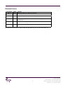
Document history Version/date 2.3 2015-1110 2.2 2013-0705 2.1 2012-1002 2.0 2010-1031 1.0 2009-1025 author Changes HOM Maven as build tool, rules for repositories HOM Ready in 7 weeks HOM HOM Move to osiris, SEBI Standard conformance: adding standard structure and elements USB version HOM initial version in LATEX Note that all versions before 2.1 are located on fontysvenlo.org, not on osiris.fontysvenlo.org. i File: main.tex Author:Pieter van den Hombergh Reviewer:Pieter van den Hombergh Revision: 13, April 15, 2013 Contents 1 Module description 1 1.1 Goal . . . . . . . . . . . . . . . . . . . . . . . . . . . . . . . . . . . . . . . 1 1.1.1 Goal in accordance with Dublin Descriptors . . . . . . . . . . . . . . 1 1.1.2 Explanation and content . . . . . . . . . . . . . . . . . . . . . . . . 1 1.1.3 Learning goals . . . . . . . . . . . . . . . . . . . . . . . . . . . . . 2 1.1.4 Grading . . . . . . . . . . . . . . . . . . . . . . . . . . . . . . . . . 3 1.1.5 Project hard- and software requirements . . . . . . . . . . . . . . . . 3 5 2 10 15 3 20 4 25 5 Requirements of an elevator system 4 2.1 Functional requirements . . . . . . . . . . . . . . . . . . . . . . . . . . . . 4 2.1.1 Safety requirements . . . . . . . . . . . . . . . . . . . . . . . . . . 4 2.1.2 Startup . . . . . . . . . . . . . . . . . . . . . . . . . . . . . . . . . 5 2.1.3 Operation . . . . . . . . . . . . . . . . . . . . . . . . . . . . . . . . 5 2.1.4 Shutdown . . . . . . . . . . . . . . . . . . . . . . . . . . . . . . . . 6 2.2 Non functional requirements . . . . . . . . . . . . . . . . . . . . . . . . . . 6 2.3 No requirement at all . . . . . . . . . . . . . . . . . . . . . . . . . . . . . . 8 Control of the elevator hardware 9 3.1 The hardware elevator . . . . . . . . . . . . . . . . . . . . . . . . . . . . . . 9 3.2 Input and outputs controlling the hardware model . . . . . . . . . . . . . . . 10 3.3 IO operations provided by the IO Warrior . . . . . . . . . . . . . . . . . . . 12 3.3.1 Bit operations . . . . . . . . . . . . . . . . . . . . . . . . . . . . . . 12 3.3.2 Bit handling . . . . . . . . . . . . . . . . . . . . . . . . . . . . . . . 13 Graphical user interface 15 4.1 15 Execution of the project 17 5.1 Products . . . . . . . . . . . . . . . . . . . . . . . . . . . . . . . . . . . . . 17 5.1.1 How to deliver your assignment products . . . . . . . . . . . . . . . 17 Naming conventions . . . . . . . . . . . . . . . . . . . . . . . . . . . . . . 18 5.2.1 Group repository . . . . . . . . . . . . . . . . . . . . . . . . . . . . 19 Weekly planning . . . . . . . . . . . . . . . . . . . . . . . . . . . . . . . . 21 Bibliography . . . . . . . . . . . . . . . . . . . . . . . . . . . . . . . . . . . . . 26 5.2 30 GUI features . . . . . . . . . . . . . . . . . . . . . . . . . . . . . . . . . . . 5.3 File: main.tex Author:Pieter van den Hombergh Reviewer:Pieter van den Hombergh Revision: 13, April 15, 2013 ii List of Figures 3.1 Door timing diagram . . . . . . . . . . . . . . . . . . . . . . . . . . . . . . 10 3.2 Elevator model . . . . . . . . . . . . . . . . . . . . . . . . . . . . . . . . . 10 3.3 Bit Listener class diagram of sevenlohwio . . . . . . . . . . . . . . . . . . . 13 iii File: main.tex Author:Pieter van den Hombergh Reviewer:Pieter van den Hombergh Revision: 13, April 15, 2013 Listings 2.1 Java doc for class . . . . . . . . . . . . . . . . . . . . . . . . . . . . . . . . 7 2.2 Java doc for method . . . . . . . . . . . . . . . . . . . . . . . . . . . . . . . 7 File: main.tex Author:Pieter van den Hombergh Reviewer:Pieter van den Hombergh Revision: 13, April 15, 2013 iv 1 What’s up doc? Bugs Bunny Module description 1.1 Goal The students achieve competences in specifying, analysis and design of a reactive system with hardware control, using UML and in implementing this system in Java. The application of Design Patterns is stimulated. The concrete elevator modelling is a good exercise in thinking about and applying design rules that have been studied in the previous module Modelling 2. 1.1.1 Goal in accordance with Dublin Descriptors The module addresses all 4 of the 5 Dublin descriptors as follows: 5 10 • Demonstrate the knowledge and understanding by applying UML, Analysis and Design Rules and Design Patterns to Analysis and Design of a moderately complex system; • Apply the knowledge and understanding in the Implementation of a moderately complex system; • Identifies and uses data to formulate responses by Analysing the system to be designed; • Communicates about understanding, skills and activities by means of a report; Of the ICT specific competences the following are addressed: 15 • Analysis • Design • Realisation 1.1.2 Explanation and content The project task is as follows: 20 1. Create a detailed analysis and design of the system using UML models. The implementation should include a hardware controlling version and a graphical simulation. It should be possible to run the program without having the hardware system available. 1 File: intro.tex Author:Pieter van den Hombergh Reviewer:Pieter van den Hombergh Revision: 14, May 13, 2013 1.1. GOAL 5 2. The UML model should be created using Visual Paradigm. We expect the following artefacts in the models: Use Case diagram including Use Case descriptions, CRC cards for the classes to be implemented, sequence diagram for the main scenarios and state diagrams for the reactive components. 3. Implementation and test of this system using Java and the IO-warrior kit to connect the hardware system to the computer. 4. Implementation and test of a GUI simulation of an elevator system in Swing. 1.1.3 Learning goals Learning goals: 10 The student is able to apply UML to an analysis and design problem for a system with a graphical and a reactive aspect in a program of medium complexity. The student is able to implement a program with graphical elements and a simulation. The student is able to programmatically control hardware. 15 20 To start a glance at Head First Object Oriented Analysis and Design (Brett McLaughlin) is worth while. In particular keep the advice in chapter 8 in mind. In the previous MOD2 module the students learned how to understand and apply patterns in theory using the book Head First Design Patterns (Eric Freeman/Bates). As additional reference the Gang of Four patterns book (Erich Gamma/Vlissides) can be used for patterns not fully covered in (Eric Freeman/Bates). Builder is of particular use in this project. For aspects dealing with state behavior (Douglass) provides a useful background. Grading is determined by the next table, showing the weights of the various aspects. Focus in examination Know- Appli- UnderProporledge cation standing tion x x 20% x x x 10% x x 30% x x x 20% x x x 20% 100% Learning Goal Modeling Embedded systems Design Patterns Programming Project work and process Previous modules are mandatory. 25 Time planning table below. File: intro.tex Author:Pieter van den Hombergh Reviewer:Pieter van den Hombergh Revision: 14, May 13, 2013 MOD1, SEN1, PRO1 and PRO2, PRJ31, MOD2. All modules mentioned The time plan of the module during the course weeks is summarised in the 2 1.1. GOAL Week of Semester Lecture Laboratory Self study Prep. Report and presentation Presentation and evaluation 1 1 4 5 7 1 4 4 8 1 Total Time 10 10 10 10 10 9 9 9 1.1.4 2 1 4 5 3 1 4 5 4 1 4 5 5 1 4 5 6 1 4 4 9 10 Total Time 1 9 28 37 4 8 2 2 5 2 84 4 4 Grading This is a group project. The grade of the individual will depend on the group grade, the peerweb peer assessment and the individual evaluation by the tutor. 5 1.1.5 Project hard- and software requirements Each group should have access to an elevator system with a USB connector. This setup allows the connection to any system supporting USB and Java. This includes Windows XP, Vista and 7, Linux in all its distributions and MAC OS-X. The USB adapter can be used safely in connection with any laptop. 3 File: intro.tex Author:Pieter van den Hombergh Reviewer:Pieter van den Hombergh Revision: 14, May 13, 2013 The risk is in the people. Or for the people. Anonymous 2 Requirements of an elevator system 2.1 Functional requirements This chapter describes some general requirements of an elevator system. The purpose of and elevator system is to transport goods or people in an efficient and safe way between floors in a building. The system may never cause any harm to its passengers or cargo. An efficient system tries to minimise waiting time for the passengers, either waiting for an elevatorcage to arrive at the floor she wants to leave or waiting for the elevator-cage she is in to arrive at the desired floor. The cages and cage shafts are grouped into shaft groups. The purpose of the shaft groups is to coordinate the cage movement to improve the provided transport service. 5 2.1.1 Safety requirements The following requirements describe the safety regulations for the system. The order in the list is also the order of priority, highest priority first. 10 1. The elevator system may never move the cage with open doors. The elevator door is considered open as long as the door close sensor (or report) is not active. 2. The elevator system must (re)open its doors if the obstruct sensor is activated, unless the door is fully closed. 3. The elevator system must have an alarm button inside the cage that forwards an alarm signal to a service post that is always able to accept this call during the service hours of the elevator system. The response time must be less than .. minutes. Outside service hours the response time be less then .. minutes. 4. The startup sequence must always result in a safe situation. 5. The shutdown sequence must always go through safe situations. File: requirements.tex Author:Pieter van den Hombergh Reviewer:Pieter van den Hombergh Revision: 12, November 28, 2012 4 2.1. FUNCTIONAL REQUIREMENTS 2.1.2 5 On startup the cage should move downward with its door(s) closed until the lowest floor sensor is activated. Once the cage arrives at the lowest floor, all requests are cancelled and the doors are opened. The doors stay open as long as there are no up or down or target requests. The startup sequence should obey the safety rules. 2.1.3 10 Startup Operation Normal operation of a cage starts at the lowest floor with the doors open. The strategy to determine the movement of the cages in a multiple cage system should be such that the strategy optimises a specific property of the system. This movement strategy should be implemented in such a way that it is replaceable (Strategy Pattern). If there are no target requests for the cage nor up or down requests from the system, we say that the cage is in the idle state. The following section describes some strategies. This list is not exhaustive. 15 Single cage strategies In any elevator system, the system services the requests in the order a cage arrives at floors. There are two major modes: 20 25 30 Full Pater Noster Always make a complete circular movement between lowest and highest floor. That is: reverse direction of the elevator only at the top or bottom floor. The movement stops if there are no more requests in the forward circular direction. On arrival of request the movement is resumed in the same direction. Skipping Pater Noster The direction may be reversed as soon as there are no more requests in the current direction. This avoids going to the extreme floors if there are no request from or to those floors. If there are no more requests or targets to visit, the cage can stay at the floor it is visiting. Example: The top floor as far as the elevator is consider is the roof of the building, which is seldom visited in daily use. The same goes for a cellar, which is floor zero as far as the elevator is considered. The normal entry to the building would then be on floor number 1. Skipping Pater Noster is the most used mode. Multiple cage strategies 35 Nurse mode Think of a hospital. When a cage is put in nurse mode, that cage only obeys its target buttons. It should not service up and down request of floors. This mode can be turned on and off by means of a (key) lockable button inside the cage. Shortest travel time This strategy tries to shorten the average travel and waiting time for all cages. Eager cage In case of eager cage, the cage tries to pick up passengers as soon as possible. 5 File: requirements.tex Author:Pieter van den Hombergh Reviewer:Pieter van den Hombergh Revision: 12, November 28, 2012 2.2. NON FUNCTIONAL REQUIREMENTS 5 When implementing Shortest travel time or Eager cage a cost model may be appropriate. A cost model computes some virtual cost of an operation and tries to minimise that cost. In this model the cost can be the respective times. Ingredients in the cost model are travelling time between floors and estimated visit duration on the floors to visit and of course the distance or number of floors to travel. 2.1.4 10 On shutdown of a cage, all requests for that cage are cancelled and the cage should stay at the current floor or move to the nearest floor in the downward direction. On arrival on that floor the cage should open its door. After a transfer timeout the doors should be closed. During the shutdown state of the entire system, the button lights should not react to up or down requests. During the shut down state pressing any target button inside the cage should trigger an alarm and reopen and then (after timeout) close the doors. 2.2 15 20 25 30 35 40 Shutdown Non functional requirements For maintainability, and quality the following non functional requirements have to be met: Resository The use of the provided group repository is mandatory. All work should be shared and comminicated via this repository. Students that at the end of the project have no commits in the repository are considered to NOT having contributed to the project. Clean Repository No compiler or linker products shall be stored in the group repository. In particular: class and jar files are not welcome in the repository. Same for generated html from javadoc. Source code All documentation, including analysis and design documents as well as all source code and configuration data shall be shared and maintained in the provided subversion repository. Package naming All package names should start with the prefix nl.fontys.sebivenlo Testing All non graphical classes should be unit tested. Unit tests for all those classes are part of the artefacts in the repository. Building Software As software building technology, maven will be used. No external libraries shall be stored in the subversion repository. External lib storage External libraries should be build in separate projects or be retrieved from their sources. Their source files should not be mixed with the application packages and files. Graphical and sound resources should be placed in the sources directory in a subdirectory named resources. Coding style Use the java coding style as introduced in PRO2 (Java, semester 2). The style will be used on svn commit on all Java code using checkstyle1 with the sebivenlo checks.xml configuration file. The svn repository is configured to only accept java files that conform this coding convention. You can find this checkstyle configuration file in the trunk of the the project svnroot https://www.fontysvenlo.org/svn/2015/prj32/ svnroot/trunk. To check you style conformance beforehand you can install the checkstyle plug-in in netbeans, which flags all non conformance in the editor. 1 Version 5.5, use the appropriate netbeans checkstyle plugin File: requirements.tex Author:Pieter van den Hombergh Reviewer:Pieter van den Hombergh Revision: 12, November 28, 2012 6 2.3. NO REQUIREMENT AT ALL 5 10 15 Code documentation All classes and interfaces in the src-tree should be documented using javadoc. All members that have external visibility (non private or have a getter) and all non private methods should have correct and complete javadoc documentation. For package info files use the modern variant package-info.java in the packages. See the java doc documentation on how to write your javadoc. Note that javadoc conformance is also part of the coding convention. Settings and properties To show various features of your product, use settings on the command line -D-option or property files liberally. Reporting Write your documentation for the intended audience. Assume that the audience is knowledgeable in Java, UML and Patterns on your own level. Write concise (short) texts, to save your and my time. Keep it intelligible though. Add small diagrams to illustrate your story. Use Pattern names in your narrative, naming the participating classes with their role in the applied pattern. Use detailed diagrams only in the appendix. Maybe you could use this report (in LATEX format) as an example. You can find it’s sources in the project repository . . . svnroot/trunk/00 modulemanual. Example of the javadoc can be seen in code snippets 2.1 and 2.2. Listing 2.1: Class javadoc example. From .../IOWarriorConnector.java 1 20 2 3 4 5 6 25 7 8 9 10 11 12 30 13 14 /* * * P r o v i d e s a c e n t r a l c o n n e c t i o n p o i n t t o t h e IO W a r r i o r s . * * T h i s c l a s s t r i e s t o open a c o n n e c t i o n t o t h e i o w a r r i o r s u b s y s t e m . * On s u c c e s s i t c r e a t e d a h a n d l e f o r e a c h i o w a r r i o r found , which c a n * be u s e d t o a t t a c h t o f o r IO o p e r a t i o n s . The h a n d l e s c a n be u s e d a s * a parameter ( e . g . in the c o n s t r u c t o r ) of c l a s s e s t h a t provide * access to the IOWarriors f u n c t i o n a l i t y . * * The C o n n e c t o r i s a S i n g l e t o n . * * @author P i e t e r van den Hombergh ( P . vandenHombergh a t f o n t y s . n l ) */ p u b l i c f i n a l c l a s s IOWarriorConnector { Listing 2.2: Method javadoc example. From .../IOWarriorConnector.java 35 1 2 3 4 5 40 6 7 8 9 10 11 45 12 13 14 15 p u b l i c s t a t i c IOWarriorConnector getInstance ( ) { r e t u r n Holder . instance ; } /* * * Get t h e h a n d l e f o r t h e i −t h w a r r i o r . * The I O W a r r i o r s a r e s o r t e d i n o r d e r o f p r o d u c t i d , s e r i a l number . * The method w i l l t h r o w an * A r r a y I n d e x O u t O f B o u n d s E x c e p t i o n i f no I O W a r r i o r s a r e f o u n d o r * i f t h e method i s c a l l e d w i t h i &g t ; = g e t W a r r i o r C o u n t ; * @param i t h e h a n d l e i n d e x r e q u e s t e d * @ r e t u r n t h e h a n d l e t o an I O W a r r i o r * @throws A r r a y I n d e x O u t O f B o u n d s E x c e p t i o n when no i o w a r r i o r s a r e * available . */ 7 File: requirements.tex Author:Pieter van den Hombergh Reviewer:Pieter van den Hombergh Revision: 12, November 28, 2012 2.3. NO REQUIREMENT AT ALL 2.3 5 No requirement at all In the organisation of our course, the students see this module at the same time they learn fundamentals about algorithms and data structures, in particular trees, lists and queues. For the students it then seems natural to use this hammer to approach the elevator problem, as in: put the requests in a queue and then deal with them by searching and sorting for the right request to service next. The secret tip is: AVOID QUEUES of any kind in your design. What I2 learned in particular is that students tend to build complex systems and than counteract design flaws with other smart solutions. 2 Author File: requirements.tex Author:Pieter van den Hombergh Reviewer:Pieter van den Hombergh Revision: 12, November 28, 2012 8 3 Those parts of the system that you can hit with a hammer (not advised) are called hardware; those program instructions that you can only curse at are called software. Anonymous Control of the elevator hardware 3.1 The hardware elevator The purpose of the software product is to control a scale hardware model of an elevator system. The model elevator has n floors, numbered 0 to n-1. For our current hardware model n=4. This simple system has the following controllable elements. 5 10 1. 2. 3. 4. 5. 15 6. 7. 8. 9. 20 10. 25 11. 12. 13. A cage to transport passengers. Up buttons, one each for the floors 0..n-2 to request a cage to a floor to move up. Down buttons, one each for the floors 1..n-1 to request to a floor to move down. n target buttons, inside the cage to request the floor to stop at a floor to let the passenger(s) out. A simulated door. In the current model the door is simulated with four LEDs. These LEDs are controlled with two inputs and two output. This simulated door is assumed to be closed when all LEDs are lit and (fully) open when all LEDs are off. This information is available via the door closed respectively door open sensor. The LEDs switch on from left to right and switch off from right to left to simulate a moving door. See figure 3.1 on the following page. A red button inside the cage. A sensor for each floor, telling that the bottom of the cage meets the floor level. A bidirectional motor. The motor’s purpose is to hoist and lower the cage. Direction LEDs which show the intended direction of travel of the cage, visible from the floor. Floor indicator LEDs to indicate where the cage is at the moment. When the cage is at a floor the matching indicator is lit. When the cage is between floors, both the indicator for the floors below and above the cage should be lit. Open and close buttons for the elevator door, located inside the cage. Obstruction sensor to reopen the doors when a passenger is between the doors. A test button which can be used to simulate the nurse mode button. 9 File: hardware.tex Author:Pieter van den Hombergh Reviewer:Pieter van den Hombergh Revision: 12, November 28, 2012 3.2. INPUT AND OUTPUTS CONTROLLING THE HARDWARE MODEL Figure 3.1: Door timing diagram 3.2 5 Input and outputs controlling the hardware model The elevator model is connected using the io-Warrior chip. This allows control of 32 io bits. In the hardware 11 bits outputs and 21 bits are used. The connections are listed in table 3.1 on the next page. Notes: The door LEDs are not in the output list. They are controlled with the door open and close command bits and can be monitored with the door opened and closed sensor as can be seen in figure 3.1 above. 10 15 20 The elevator motor is controlled with two bits. It has two LEDs connected, one for up and one for down, which light up when the motor is switched on in that direction. The LEDs are on the bezel or pedestal, out of sight of the passenger. Left and right of the floor indicator lights on each floor, there is one up and down LED. These LEDs should show the travel direction chosen by the elevator control. These up/down LEDs should go off when the elevator has no more calling or moving passengers. In this project the hardware model is connected using the IO warrior chip. This is then connected to the USB port of a computer (PC or MAC). 25 The inputs and outputs are pure binary, which allows the use of one bit for each of the inputs and outputs. An active bit has value 1 in the aggregate, an inactive bit value 0. File: hardware.tex Author:Pieter van den Hombergh Reviewer:Pieter van den Hombergh Revision: 12, November 28, 2012 10 Figure 3.2: Elevator model 3.2. INPUT AND OUTPUTS CONTROLLING THE HARDWARE MODEL Table 3.1: Hardware connections of the elevator model in/out bitNr warrior bit control in 0 P0.0 up button 0 in 1 P0.1 up button 1 in 2 P0.2 up button 2 in 3 P0.3 down button 1 in 4 P0.4 down button 2 in 5 P0.5 down button 3 in 6 P0.6 door closed sensor in 7 P0.7 red cage button (alarm button) in 8 P1.0 target button 0 in 9 P1.1 target button 1 in 10 P1.2 target button 2 in 11 P1.3 target button 3 in 12 P1.4 floor sensor 0 in 13 P1.5 floor sensor 1 in 14 P1.6 floor sensor 2 in 15 P1.7 floor sensor 3 out 16 P2.0 floor indicator light 0 out 17 P2.1 floor indicator light 1 out 18 P2.2 floor indicator light 2 out 19 P2.3 floor indicator light 3 out 20 P2.4 Motor down bit out 21 P2.5 Motor up bit out 22 P2.6 door open cmd out 23 P2.7 buzzer (avoid)/blue led test Bits below are extensions on previous hardware in 24 P3.0 (nurse button) (test) out 25 P3.1 up led out 26 P3.2 down led out 27 P3.3 door close cmd in 28 P3.4 door open sensor in 29 P3.5 door open button in 30 P3.6 door close button in 31 P3.7 obstruction sensor All bits are in true logic. A one activates LED or motor-bit, a 0 turns it off. For inputs: a 1 is an activated sensor or button, a 0 is the inactive state. 11 File: hardware.tex Author:Pieter van den Hombergh Reviewer:Pieter van den Hombergh Revision: 12, November 28, 2012 3.3. IO OPERATIONS PROVIDED BY THE IO WARRIOR 3.3 IO operations provided by the IO Warrior 5 10 The operations provided by the IO Warrior development kit can be found in the Java documentation. For your convenience we provide a copy of the IOwarrior software development kit api at http://prj32.fontysvenlo.org/iowarrior-SDK/Java/doc/ api/index.html. The SDK can also be found at the prj32 web page http://prj32. fontysvenlo.org/. To get you started and to remove some startup and shutdown issues we provide a few utility classes in the package sevenlohwio. This package and some more packages is also available in the project repository. 3.3.1 15 20 25 Bit operations The basic read and write operations on most computer binary IO is word wide, in which the word with is 8, 16 or 32 bits at a time. In most smaller systems, including the PC, the minimum amount is 8 bits or a byte. In the case of the IOWarrior we have an USB Human intarface device. We use the IOWarrior in its simplest mode, in which case its provides access to it IO pins with read and write of all the 32 bits at a time. As an abstraction we define two interfaces that should implemented and on which you can design and implement a complete binary IO subsystem. The basic operations defined in the interfaces are int read() and void write(int v). Implementing these interfaces enables encapsulation of the IO device in classes. The object of such an implementation class could for instance encapsulate an IOWarrior or a network connection to an iowarrior connected to another computer. The identification of the proper port and connector or IOWarrior address should be taken care of in the constructor in the class design, which assigns the port and card info to final fields. Specific to the IOWarrior is that it behaves as a so called Human Interface USB device, that is, it behaves similar to a keyboard or mouse. This implies that a read operation only returns if there is input. Such a operation is called a blocking operation. 30 35 Your main task in the project related to IO is to provide bit handling. In particular you will have to implement the detection of the input bit changes and notification of observers or listeners. Of course you will have to design and implement the bit output operations as well. We strongly suggest that you make use of a change-Listener design, which is similar to an instance of the Observer Pattern combined with Adapter. The listeners are then driven by a method, void pollOnce() defined in the interface Poller that periodically or regularly interrogates the input word. In the class diagram in figure 3.3 you find part of the hwio library. The white classes and interfaces are the ones that you might want to extend or implement. In particular you will want to implement BitListener(s) and the AbstractBitFactory, which produces InBit and OutBit Objects or derivatives of thereof. File: hardware.tex Author:Pieter van den Hombergh Reviewer:Pieter van den Hombergh Revision: 12, November 28, 2012 12 3.3. IO OPERATIONS PROVIDED BY THE IO WARRIOR hwio <<Interface>> BitOps (hwio) +isSet() : boolean +set(b : boolean) : void <<Interface>> BitAggregate (hwio) +getBit(i : int) : BitOps +size() : int +getInputMask() : int +lastRead() : int +connect() : void <<Interface>> BitSubject (hwio) +addListener(bl : BitListener) : void +removeListener(bl : BitListener) : void Bit (hwio) +set() : void +clear() : void +addListener(bl : BitListener) : void +removeListener(bl : BitListener) : void #updateListeners(bo : Object, newValue : boolean) : void <<Interface>> BitListener (hwio) +updateBit(bit : Object, newValue : boolean) : v... SwingPoller (hwio) -lastValue : int = 0 -bitA : BitAggregate OutBit (hwio) -mask : int -writer : Output -value : boolean +SwingPoller(b : BitAggregate) +pollOnce() : void InBit (hwio) -value : boolean = false -bitNr : int +InBit(bnr : int) +set(b : boolean) : void +isSet() : boolean <<Interface>> AbstractBitFactory +createInputBit(port : Input, bitNr : int) : Bit +createOutputBit(port : Output, bitNr : int) : Bit BitUpdater (hwio) +updateIntegerBits(bitAg : BitAggregate, oldValue : int, newValue : int) : void -BitUpdater() Figure 3.3: Bit Listener class diagram of sevenlohwio 3.3.2 Bit handling To be able to isolate or operate on bits in word1 you need a few bitwise logical operation. 5 NOT inverts all bits in a word, that is a 0 becomes a 1 and a 1 becomes zero. Mathematical example: a = 01010101 ¬a = 10101010 The Java (and C) symbol for the bitwise not operator is˜as in ˜a. AND a bit in the result is 1 if all the corresponding bits in all arguments are 1, else 0. Mathematical example: a = 01000101 b = 00011111 a ∧ b = 00000101 10 The Java symbol is the single ampersand (&) as in r = a & b. OR a bit in the result is 1 if the any of the corresponding bits in the arguments is one, else 0. Mathematical example a = 01000101 b = 00011111 a ∨ b = 01011111 The Java symbol is the single vertical bar (|) as in r = a | b. 1 Word is any group of bits in this context, in the examples you will see groups of 8, named octet or byte , but short , integer and long are also words in this context. 13 File: hardware.tex Author:Pieter van den Hombergh Reviewer:Pieter van den Hombergh Revision: 12, November 28, 2012 3.3. IO OPERATIONS PROVIDED BY THE IO WARRIOR XOR exclusive or. A bit in the result is 1 if exactly one of the corresponding bits is 1. a = 01000101 b = 00011111 a ⊕ b = 01011010 The Java symbol is the hat (ˆ ) as in r = a ˆ b. With two arguments the xor operation tells you which of the bits differ in the arguments. 5 A summary of the logical operations with two one bit arguments is given table 3.2 Table 3.2: Some logical operations Logical operations (in bit wise programming notation) semantics inverse all (both) at least one unequal equal not all none math sym ¬a a∧b a∨b a⊕b a=b ¬(a ∧ b) ¬(a ∨ b) techn. not. a a·b a+b a⊕b a=b a·b a+b C style. not. ˜a a&b a|b aˆb a == b ˜(a&b) ˜(a|b) a b not(a) and or xor equals nand nor 0 0 1 0 0 0 1 1 1 0 1 1 0 1 1 0 1 0 1 0 0 0 1 1 0 1 0 1 1 0 1 1 0 1 0 0 File: hardware.tex Author:Pieter van den Hombergh Reviewer:Pieter van den Hombergh Revision: 12, November 28, 2012 14 4 All our dreams can come true, if we have the courage to pursue them. Walt Disney Graphical user interface The current hardware model is somewhat limited and misses some features that you would expect in a real elevator system. To make the modelling more realistic we compensate for these missing features in the graphical user interface. You should use the Java Swing framework to implement the graphical user interface of the system. There are a number of nice tutorials on the web, such as http://java.sun.com/docs/books/tutorial/uiswing at the Oracle/SUN website. The document http://java.sun.com/products/jfc/tsc/articles/painting/ is very useful in understanding the architecture of painting in AWT and swing. 4.1 GUI features Lit buttons In a modern elevator system you expect lit buttons. Once a button is pressed, the button is lit. This light stays on until the service requested by the passenger is provided. As an example: when a passenger presses an UP button on floor f, the button’s light stays on until a cage visits floor f in an upward journey. In the GUI presentation all buttons should have lights. Obstruction detection A modern elevator, or any automatically closing door for that matter, will have some kind of an obstruction sensor. In the GUI this sensor can be simulated by implementing the GUI cage as some kind of button, in which the pressed state equals obstruction. Door Open and close buttons A cage in an elevator system should have an open and a close button, that requests the door to be opened or closed. Once an elevator has a request which takes it to another floor, the door is closed. If a cage stops at a floor a transfer timeout must be observed, which can be shortened by pressing the door close button and extended by pressing the door open button. Of course the door should only open if the cage is at rest at a floor. 15 File: gui.tex Author:Pieter van den Hombergh Reviewer:Pieter van den Hombergh Revision: 14, May 13, 2013 4.1. GUI FEATURES Cage position indication As in the hardware model, the GUI should also show the whereabouts of the cage on some kind of indicator on each floor. The same approach as the hardware (two lights when between floors) can be used. A dial model, such as used in old fashioned elevator systems would be a very nice touch. Multiple cages A serious elevator system would have multiple cages, making a strategy for up and down buttons more meaningful to system and passengers. In your implementation you should be able to support at least two cages in the GUI, where one of these GUI cages will monitor the hardware elevator model. The idea is that this GUI cage presents the behaviour of the hardware model, synchronous to that model. You should try to make an attempt to let the GUI and the hardware model move as synchronously as possible. The GUI cage will have all the missing features as mentioned above and otherwise mimic the hardware model faithfully. For instance if the red button is used as the obstruct button, and the monitor provides obstruction behaviour, then both the hardware cage and this monitor cage should reopen its door and wait for the obstruction to be removed. Nurse button The nurse button should also be present in the GUI. Number of floors The GUI design should be able to support at least 10 floors. Logging The system should log all up and down requests and arrivals as well as the motor cycles of all cages. (Up, down, stop). The tail of this log (the last entries) should be shown in the GUI. Floor announcement Once the elevator stops at a floor due to a target request, an audible floor announcement is given. In an extended version of the system, this floor announcement may have a different announcement signal for each floor. Simple but distinct sounds can be used but thinkable is something like “fourth floor, penthouse and restaurant”. The floor announcement system could also be used to inform the passengers of special situations like out of order messages and the like. File: gui.tex Author:Pieter van den Hombergh Reviewer:Pieter van den Hombergh Revision: 14, May 13, 2013 16 5 Genius is one percent inspiration and ninety-nine percent perspiration. Thomas A. Edison Execution of the project The main focus of this project is on reactive systems and usage of design patterns. This explains why we enforce a rather strict plan, to make sure that all goals are met and groups do not get into trouble due to inadequate planning. Note that the planing is quite tight. So not only work as a team towards the next delivery (there is one every week), but properly use all available manpower. That is: Near a delivery deadline most of your team members should be done with the work for that deadline and 2 project members are involved in preparing the demo for the deadline. The others should be working on investigating the deliverables for the next deadline. 5.1 Products The products of this assignment are: 1. Report 2. Model 5 3. Implementation 5.1.1 How to deliver your assignment products All electronic products must be handed in via peerweb. See peerweb for all deadlines. 10 15 1. Report: one document describing your analysis, design and its implementation, test installation and user manual to be handed in on paper too, properly bound at the copy shop. The document should also contain a reference to the repository. See the weekly plan for what the document should contain. The design diagrams, user interface illustrations etc. are copied into and explained in the report document. In the document code fragments are shown only when relevant. E.g. when the implementation is discussed in the describing text. 2. Models: One model file in the Visual Paradigm UML tool. The models should contain analysis, design and implementation as well as a reverse engineered model of the complete implementation. For practical reasons you may use more then one model file for 17 File: weekplan.tex Author:Pieter van den Hombergh Reviewer:Pieter van den Hombergh Revision: 23, November 8, 2013 5.2. NAMING CONVENTIONS each of the phases analysis, design and implementation. You may hand in three distinct models. 5 3. Implementation: All (re)sources needed to build the project should be in the project repository at all times. The sources should be accompanied with an ant build script. Most of the time the Netbeans build.xml script will do. For all but the first week you should produce a executable artefact or runnable program. By checking out the project and calling ant jar should result in a functional and runnable jar file. Say the produced jar file is called dist/SuperElevator.jar I will use the file like this: java -cp dist/SuperElevator.jar nl.fontys.sevenlo.prj32.DemoWeekX. 10 The prefix nl.fontys.sevenlo.prj32 is mandatory for all your packages. You may (maybe should) have additional packages under this top package name. You may also create several Netbeans projects with additional package and directory structures to reflect your functional decomposition. 15 Each week that has an executable will have a Main class named nl.fontys.sevenlo.prj32.DemoWeekweeknr. For each week, except the first, there will be a hand in of a runnable jar file. 5.2 20 Naming conventions Libraries You will be using supplied libraries for the control of the hardware. You may look at it as a layered architecture. The hardware layer is provided by the IOWarrior Library. It is provided by the manufacturer of the IOWarrior chip, Code Mercenaries GmbH. The bit io abstraction layer is provided by sevenlohwio library. It provides a bit wise io abstraction. 25 The sevenlowarrior combines the facilities provided by the hardware with the abstraction layer and thus provides USB based bitwise io. For testing purposes in a gui environment sevenlowarrior uses the sevenlowidgets library. Aside the use for iowarrior testing it also provides some goodies that can be use full in your elevator implementation. 30 The widgets library itself uses some resources that must be loaded from the class path. We use sevenloutils for that. To be able to use these libraries in a platform and java/netbeans installation independent way, create netbeans libraries. You get most comfort if you install the libraries complete with source and javadoc. 35 The names of these libraries and the installation1 steps as netbeans library are: CodeMercenaries The hardware access layer. [Classpath] The library proper is at /usr/share/java/codemercs.jar. [Source] Add the file /usr/share/java/codemercs-src.jar. [Javadoc] Add the file /usr/share/java/codemercs-doc.zip. 1 The paths used are for Debian/Ubuntu Linux. File: weekplan.tex Author:Pieter van den Hombergh Reviewer:Pieter van den Hombergh Revision: 23, November 8, 2013 18 5.2. NAMING CONVENTIONS SEVenloHWIO The bit io abstraction layer. [Classpath] The library proper is at /usr/share/java/sevenlohwio.jar. [Source] Add the file /usr/share/java/sevenlohwio-src.jar. [Javadoc] Add the file /usr/share/java/sevenlohwio-doc.zip. 5 SEVenloWarrior The bit io abstraction layer. [Classpath] The library proper is at /usr/share/java/sevenlowarrior.jar. [Source] Add the file /usr/share/java/sevenlowarrior-src.jar. [Javadoc] Add the file /usr/share/java/sevenlowarrior-doc.zip. 10 SEVenloWidgets The gui widgets. [Classpath] The library proper is at /usr/share/java/sevenlowidgets.jar. [Source] Add the file /usr/share/java/sevenlowidgets-src.jar. [Javadoc] Add the file /usr/share/java/sevenlowidgets-doc.zip. SEVenloUtils The resource utils. [Classpath] The library proper is at /usr/share/java/sevenloutils.jar. 15 [Source] Add the file /usr/share/java/sevenloutils-src.jar. [Javadoc] Add the file /usr/share/java/sevenloutils-doc.zip. All these libraries can be found at the module website. 20 25 To ease your getting into the matter, we’ve created a project in GIT, containing a sub directory containing a maven netbeans project, called bitfactoryexample. You can clone it with the coordinates [email protected]:2013/prj32m1/g4. You should be able to build and run this project. The command line way to build it is mvn compile assembly:single, which will build a singe jar containing all the required libraries. This maven command should pull in all the required resources and libraries. If you also would like to get the sevenlo libraries described above. Clone the repository [email protected]:2013/prj32m1/g4. 5.2.1 Group repository 19 File: weekplan.tex Author:Pieter van den Hombergh Reviewer:Pieter van den Hombergh Revision: 23, November 8, 2013 5.2. NAMING CONVENTIONS The repository contains a predefined directory structure. All source code (including tests) should be placed under sources. The doc directory is intended for the documentation including the analysis and design models. Use Visual Paradigm for your UML modelling. It also integrates quite well with subversion2 through its team work capabilities. The doc directory strongly hints at preparing your report using LATEX. Project name The netbeans projects shall be named with a group prefix in front of them in the form of gx , where x is one of 01. . . 04 as in g01 elevator. This also applies if you split your whole project into several (netbeans) sub-projects for instance for specific subsystems. This is a good idea anyway. So you might have a g01 guiwidgets library project. At the end you will have to deliver the complete deployable binary in a zip file. This zip file will have the name gx elevator.zip. This zip file must contain all that is needed to deploy the applications via web start, using the jnlp protocol. The zip file should contain all that is packed into the dist subdirectory, including the dist subdir itself. In Linux that would be the zip -r g01 elevator.zip dist -command. Tagging and branching of the documentation (doc) subtree is not required. However the sources subtree will be tagged each week (see below). A tag (and a branch) are simple copy commands in subversion. See the appropriate documentation in the svnbook at http://svnbook.red-bean.com/en/1.5/svn.branchmerge. tags.html. Use the appropriate source and destination urls and all is done on the server with minimal delay. Being versed at the subversion command line is very rewarding here. If not sure, try things first in your personal scratch pad repository. In git, tagging is simple too, See http://git-scm.com/book/en/Git-Basics-Tagging. Tags Each week the tutors will make a TAG with the name pattern TAG WEEKx. Other TAGS may be used freely. Branches You develop on the trunk, which is where the most project members are working. Near a deadline, some will be preparing for the demo of that period. Consider using a branch for the last preparations so that work by others does not inter fear with your demo project. From there pick up the stuff from the trunk in a controlled way by applying the proper merge commands from trunk. Consider branch names like LOGIC RELEASE etc. In Git you do not need branches for a local experiment, as long as you do not push the incomplete experiment results to the origin. 2 with git I do not know File: weekplan.tex Author:Pieter van den Hombergh Reviewer:Pieter van den Hombergh Revision: 23, November 8, 2013 20 5.3. WEEKLY PLANNING Final delivery The final deliveries are: reports in pdf file format and a java web start enabled jar bundle. Making a web start-able project in netbeans is fairly easy. Use the project properties and enable web start, Select • [Codebase]: User defined (e.g. HTTP Deployment), and • [Codebase Preview:] http://prj32.fontysvenlo.org/2011/gx elevator/dist/launch.jnlp, substituting x with your group number. Running ant jws-run with these settings will fail locally, but will produce a correctly populated dist subdirectory. 5 5.3 10 Weekly planning The weekly rhythm must be strictly observed. The hand in for all but the last deliverable will all be done using subversion to the URL for your group as mentioned on the PRJ32 website. As hand in time the svn time is taken. Note that this always is UTC, thus not the same as your wall clock time. During all project weeks you will keep a time record of all the time spent on the project. At the end of each project week the tutor will tag the repository with a read only tag for all groups. The material in the tag is considered handed in. The rest is not. 21 File: weekplan.tex Author:Pieter van den Hombergh Reviewer:Pieter van den Hombergh Revision: 23, November 8, 2013 5.3. WEEKLY PLANNING Table 5.1: Week plan week delivery Task and product Analysis Use case description describing the main success scenarios (including the alarm scenario). (Hint: subdivide the journey into 4 sub scenarios; there is also an alarm scenario). Use case diagrams showing the relations between the use cases. Analysis class diagram including CRC descriptions of the classes 1 Sequence diagrams of the main scenarios. If you folSCM lowed the advice in the use cases you should have 5 TAG WEEK1 sequence diagrams. State model The system obviously has state behaviour. Model this state behaviour of the system and its subsystems using state diagrams. Data model Data model is a posha word for how to keep track of all requests and commands of the elevator system. Design a data model with appropriate operations. The data model may keep up and down requests separate from target requests. From the start think of multiple shaft systems. a Posh is the not so posh word for chique week plan continued on next page File: weekplan.tex Author:Pieter van den Hombergh Reviewer:Pieter van den Hombergh Revision: 23, November 8, 2013 22 5.3. WEEKLY PLANNING Table 5.1: Week plan week delivery Task and product Hardware subsystem and Data model Analysis, design and implementation of the hardware IO subsystem. The hardware elevator will be connected using USB and a small IOWarrior printed circuit board. You will be given the complete IOWarrior library (which is available from code mercenaries) plus a library that provides the elementary read and write operations to the hardware. Deliverables: 2 SCM Class model IO subsystem A complete design class TAG WEEK2 model of the system. For the report you will need diagrams of the subsystems. Implementation of IO subsystem As usual: no implementation is complete without tests. Data model and implementation including tests of all the operations. The test on the data model must have 100% statement coverage, to be determined with the Emma coverage plug in. GUI and simulation design and design and implementation of the widgets used in this design. Deliverables: Drawing of the gui design I would use inkscape. You might want to opt for Adobe Illustrator or a similar tool. Make sure you are able to deliver a vector type file. (SVG or PDF). 3 SCM TAG WEEK3 Widgets The Cage which should provide obstruction detection functionality. Up and down buttons including the appropriate. Floor sensor indicators which show when a floor sensor is activated. ButtonModels. Target buttons. Note that all these widgets get rather little real estate in the GUI picture. State machine (s) implementation for the behaviour of the system. week plan continued on next page 23 File: weekplan.tex Author:Pieter van den Hombergh Reviewer:Pieter van den Hombergh Revision: 23, November 8, 2013 5.3. WEEKLY PLANNING Table 5.1: Week plan week delivery Task and product Data model and GUI integration Deliverables: 4 Integrated GUI simulation that shows the functionality of the widgets and the whole system so far. This SCM simulation should already behave like a normal TAG WEEK4 elevator system with respect to state behaviour. The data model should be used. Strategy design Use the Strategy pattern to implement different behaviours of the system in several modes. Implement one simple but useful strategy. GUI - hardware integration with simple strategy. 5 SCM TAG WEEK5 Combined hardware and software model in which the GUI shows two cages, one simulation and the other as a monitor to the hardware model. This implementation must be working for a building with 4 floors. Additional strategy implementations Strategy implementations for the remaining operating modes. Documenting, presentation and demo preparation 6 SCM TAG WEEK6 Complete class documentation extract-able with javadoc. all diagrams for the report. Report with sections requirements, analysis, design, implementation details, test plan describing what you intended to test, deployment manual and a User manual. week plan continued on next page File: weekplan.tex Author:Pieter van den Hombergh Reviewer:Pieter van den Hombergh Revision: 23, November 8, 2013 24 5.3. WEEKLY PLANNING Table 5.1: Week plan week 7 delivery Task and product Delivery week in which the products are presented and demonstrated. During this demonstration the use of compilers, editors and the like is forbidden. All code should be runnable in delivered binary form. For Java that would SCM + be a jar file, possibly combined with a startup script. You peerweb may use several startup scripts to show different features TAG WEEK7 of your application, but all should use the same (set of) jar +reports file(s). (.pdf) All groups will provide a zip file that contains an appliin peerweb cation that is deployable through a web site using Java presentation web start. This zip file must be self contained and have no and external dependencies that have to be pre-installed. This demo should provide us to have very nice set of demo applications. See the netbeans documentation on how to do that. This application should be able to work with and without the iowarrior drivers and libraries installed. All students must attend the presentation demonstration of all groups. Final execution report Time usage sheets for all group members summarised over the whole project. Defects report Defects found during tests and integration with an impact analysis. An impact analysis describes what the subsequent effect of this defect is on the rest of or the overall system . End of week plan 25 File: weekplan.tex Author:Pieter van den Hombergh Reviewer:Pieter van den Hombergh Revision: 23, November 8, 2013 Bibliography Brett McLaughlin, Gary Pollice, David West: Head First Object-Oriented Analysis and Design. O’Reilly, 2006, ISBN ISBN 10: 0–596–00867–8 — ISBN 13: 9780596008673 5 Douglass, Bruce Powel: Doing Hard Time: Developing Real-Time Systems with UML, Objects, Frameworks, and Patterns. Addison-Wesley, 1999, ISBN ISBN–10: 0201498375—ISBN–13: 9780201498370 Eric Freeman, Elisabeth Robson, Kathy Sierra/Bates, Bert: Head First Design Patterns. O’Reilly, 2004, ISBN ISBN 10: 0–596–00712–4 — ISBN 13: 9780596007126 10 Erich Gamma, Richard Helm, Ralph Johnson/Vlissides, John: Design Patterns: Elements of Reusable Object-Oriented Software. Addison Wesley, 1995, ISBN ISBN 0–201– 63361–2 File: weekplan.tex Author:Pieter van den Hombergh Reviewer:Pieter van den Hombergh Revision: 23, November 8, 2013 26 Bibliography Colofon The original hardware model is provided by Hogeschool Rotterdam. 5 The model currently in use has undergone several revisions. The latest model has been built with a USB only connection, with added hardware functionality (full door control, open/close buttons, test obstruction and nurse button) is a idea of Pieter van den Hombergh. The electronics and the new mechanics has been designed and built by VeTeTronics B.V., Tegelen. The drawing of the model on page 10 is made by Denny Beulen. 10 The design and manufacturing of the box at the underside has been produced by Jochem Högerle at the Fontys Hogeschool voor Techniek and Logistiek laboratory for mechanical production. The software libraries are designed and maintained by Pieter van den Hombergh. 27 File: weekplan.tex Author:Pieter van den Hombergh Reviewer:Pieter van den Hombergh Revision: 23, November 8, 2013 Fontys SEBI Venlo Series Fontys Hogeschool voor Techniek en Logistiek Software Engineering/Business Informatics Tegelseweg 255 5912 BG Venlo The Netherlands