1
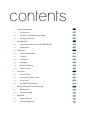
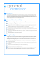
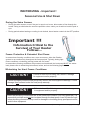
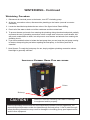
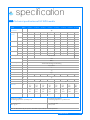
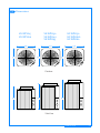
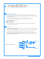
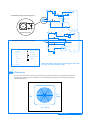
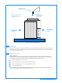
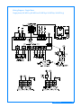
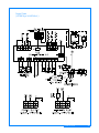
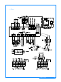
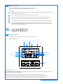
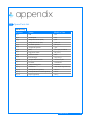
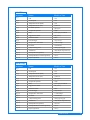
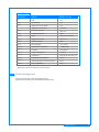
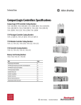
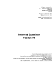
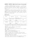
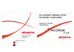
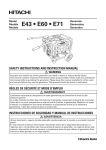
SWIMMING POOL HEAT PUMP UNIT
Installation & Instruction Manual
installation manual
contents
General Information
01
1.1)
Introduction
01
1.2)
Consumer Information and Safety
01
1.3)
Energy Saving Tips
02
1)
2)
Specifications
02
2.1)
Technical specifications of VA-WPH Models
02
2.2)
Dimensions
03
3)
Installation
04
3.1)
General Information
04
3.2)
Location
04
3.3)
Clearance
05
3.4)
Drainage
06
3.5)
Electrical Wiring
06
3.6)
Initial Startup
10
4)
Operation
10
4.1)
Control Panel
10
4.2)
Instruction of SMS control
12
4.3)
Error Code
13
4.4)
Operation Data Setting
13
5)
Maintenance and Trouble Shooting
13
5.1)
Maintenance
13
5.2)
Troubleshooting
14
6)
Appendix
15
6.1)
Spare Parts List
15
6.2)
Acknowledgement
19
general
1
information
1.1
Introduction
This manual provides installation and operation instructions for the heat pumps .Read these installation and operation instructions
carefully before proceeding with the installation. Consult the local distributor with any questions regarding this equipment. Please
read this manual carefully before you install. Start, repair or maintain the unit. Installation and service must be performend by a
qualified installer.The manufaturer shall not be responsible for any damage of the unit or physical injury or death caused by improper
installation,debugging, operation,maintenance or disregarding the manual.
1.2 Consumer Information and Safety
1.
We recommend 80°F (27°C )as the optimun water temperature for swimming. Overheated water may cause tiredness and
reduce comfort of swimming.
2.
The drinking of alcoholic beverages before or during spa or hot tub use can cause drowsiness which could lead to unconsciousness, and subsequently result in drowning.
3.
Pregnant women take note! Soaking in water above 102°F (38.5°C ) can cause fetal damage during the first three months
of pregnancy (which could result in the birth of a brain-damaged or deformed child). If pregnant women are going to use a spa
or hot tub, they should make sure the water temperature is below 100°F (38°C ) maximum.
4.
The water temperature should always be checked with an accurate thermometer before entering aspa or hot tub.
5.
Persons with a medical history of heart disease, diabetes, circulatory or blood pressure problems should consult their physician
before using a hot tub or spa.
6.
Persons taking any medication which induces drowsiness (e.g., tranquilizers, antihistamines, or anticoagulants) should not use
spas or hot tubs.
7.
Prolonged immersion in hot water can induce hyperthermia.
1.3 Energy Saving Tips
It is important to note that a heat pump will not heat a pool as fast as a large gas or electric pool heater. If the pool water is allowed to
cool significantly, it may take several days to return to the desired swimming temperature. For weekend use, it is more economical to
maintain the pool water temperature at or near your desired swimming temperature. If you do not plan to use your pool for a
prolonged period, then you might choose to turn the heat pump completely off or decrease the temperature setting of the control
several degrees to minimize energy consumption.
1.
Use an accurate pool thermometer. A difference of 4°F (2°C ) , between 78°F and 82°F (26°C and 28°C ), will significantly
increase energy consumption.
2.
Carefully monitor the water temperature of your pool in the summer time. You can reduce heat pump usage due to warmer air
temperatures.
3.
During the winter or when on vacation for longer than a week, turn off the heat pump.
4.
Find the proper setting on the heat pump temperature control
5.
Where possible, shelter the pool from prevailing winds with well-trimmed hedges or other landscaping, cabanas, or fencing.
6.
Always use a pool cover when practical. Besides providing a valuable safety feature, a pool cover will reduce heat loss.
installation manual
01
WINTERIZING - Important !
Seasonal Use & Shut Down
During the Swim Season:
•
During the swim season, even if the pool or spa is not in use, allow water to flow through the
heater. Doing so eliminates the need to reposition valves when you do wish to heat the pool or
spa.
•
During periods when heating or cooling is not desired, leave heater controls in the OFF position.
Important !!!
Information Critical to the
Survival of Your Heater
Follows...
Freeze Protection & Extended Shut Down:
In areas where freezing conditions are a rare occurrence, allow the filtration
system to run continuously throughout the freeze period. Typically, during light
freeze conditions, circulating (moving) water will not freeze.
In areas where freezing conditions are prevalent and sustained, the heat pump MUST be winterized; please refer to winterizing instructions, below, and on the following pages.
Winterizing for Hard Freeze Conditions:
CAUTION !
Failure to heed the following can result in damage
to equipment and/or property.
Failure to properly winterize heat pump may result in serious equipment damage. Freeze
damage is not covered under the heat pump warranty.
CAUTION !
Failure to heed the following can result in damage
to equipment and/or property.
While the plumbing connections are in the winterized condition (not fully tightened), it is
imperative pool/spa waternot be circulated through the heat pump. Loss of water through
loose plumbing connections may result in damage to circulating pump, pool/spa structure,
and/or other equipment.
(Winterizing continued on page following)
WINTERIZING - Continued
Winterizing Procedure:
1. Disconnect all electrical power to the heater; turn OFF circulating pump.
2. At the two connection unions, disconnect the plumbing to the heater (removal is counterclockwise).
3. Locate the hand drain tap below the two unions. See figure below. Rotate 90Deg.
4. Permit all of the water to drain out of the condenser and then rotate back
5. To prevent insects and vermin from entering the plumbing during the winterized period, partially
reconnect the two (2) plumbing connection unions: couple each union one or two threads; this
will permit condensation to drain, but will prevent most insects and animals from entering the
plumbing circuit.
6. If you have used ball valves to isolate the heat pump then you can keep the pool pump running
in winter or keep using the pool when repairing the heat pump, or for indoor pools this is
essential
7. Next Season: To ready the heat pump for use, simply retighten plumbing connection unions.
Hand-tight is generally sufficient.
LOCATION OF EXTERNAL DRAIN PLUG
AND UNIONS
Unions
Drain tap
CAUTION !
Failure to heed the following can result in damage
to equipment and/or property.
While the plumbing connections are in the winterized condition (not fully tightened), it is
imperative pool/spa water not be circulated through the heat pump. Loss of water through
loose plumbing connections may result in damage to circulating pump, pool-spa structure,
and/or other equipment.
specification
2
2.1
Technical specifications of VA-WPH models
Item
Units
VA-WPH15
VA-WPH20
VA-WPH30
VA-WPH40
Current
VA-WPH60
37150
42625
44330
57970
63085
68200
92070
92070
W
11000
12500
1300
17000
18500
20000
27000
27000
BTU/H
24552
32395
35805
54560
58652
61380
85250
85250
W
7200
9500
10500
16000
17200
18000
25000
25000
F
W
1320
1900
2730
2750
3300
4300
5100
6000
E
W
1200
1800
2470
2600
3100
3750
4700
5500
F
6.22
6.58
4.76
6.18
5.61
4.65
5.32
4.50
E
6.0
5.28
4.25
6.15
5.55
4.80
5.29
4.55
E
COP
VA-WPH60L
BTU/H
F
Capacity
Power Input
VA-WPH50
Top
Fan Location
Heating
VA-WPH45
F
A
6.5
8.7
13.2
14.3
15.8
22.5
24.0
10.3
E
A
5.7
8.2
11.8
13.6
15.0
19.5
22.2
9.7
Power Supply
V/Ph/Hz
380/3/50
220-240/1/50
Compresor
1 Set
Rotary
Heat exchanger
Titanium heat exchanger in PVC housing
Refrigerant
R407c / R22
Fan Amount
1
Power Input of Fan
W
175
Rotate Speed
RPM
650
Noise Level
dB(A)
Connections
mm
Water Flow
m3/h
Water Pressure Drop
kPa
Dimension
mm
575*
575*
680
575*
575*
780
575*
575*
780
575*
575*
780
575*
575*
780
Package Size
mm
710*
710*
820
710*
710*
820
710*
710*
920
710*
710*
920
N.W/G.W
Kg
54/68
58/72
64/78
75/90
47
47
47
51
54
56
58
58
6.0
3
4.5
6
575*
575*
880
575*
575*
880
575*
575*
880
710*
710*
920
710*
710*
1020
710*
710*
1020
710*
710*
1020
88/103
98/113
100/115
102/117
50
2.2
4.5
3
6
10
12
F-factory test conditions
surrounding temperature : 24ºC db/19ºC wb
E-european test conditions
surrounding temperature : 15ºC db/11ºC wb
27º Centering water
COP : 4.5-7.0
27º Centering water
COP : 4.0-6.1
Note : the above data are for your reference. There will be no prior notice for technical improvement
installation manual
02
2.2 Dimensions
VA-WPH15
VA-WPH20
575
575
VA-WPH30
VA-WPH40
VA-WPH45
VA-WPH50
VA-WPH60L
VA-WPH60
575
575
575
575
Platform
680
880
780
Side View
installation manual
03
installation
3
3.1 General Information
Inspect the casing,unit and spare parts after receipt for possible for possible damage in transportation. Check whether there is
breakage of the casing and cabinet, deformation of the unit,shed parts.The manufacturer shall not be responsible for any damage due
to improper hanging or shipping.
Install the heat pumps in accordance with the procedures in this manual, lacal codes and ordinances.
Correct installation is required to assure safe operation.The requirements for heat pumps include the following:
1.
2.
3.
4.
Appropriate site location and clearances.
Sufficient air ventilation.
Proper elevtrical wiring.
Adequate water flow.
This manual provides the information needed to meet these requirements. Review all application and installation procedures
completely before continuing the installation.
3.2 Location
The unit should be usually installed outdoor (NOTE: Indoor installations require special considerations for condensate drainage and
venting the cold air produced by the heat pump.)
Install the unit downstream of all pumps and filters and upstream of all chlorinators,ozonizers and chemical pumps.
Keep lawn sprinkler heads from spraying on the heat pump to prevent corrosion and damage .Use a deflector if needed.
Make sure the heat pump is not located where large amounts of water may run-off from a roof into the unit. Sharp sloping roofs
without gutters will allow massive amounts of rain water ,mixed with debris from the roof to be forced through the unit. A gutter or
down spout may be needed to protect the heat pump.
P
H
D
F
H
S
P|T
Multiple Heat Pump Installation
H
PARALLEL
R
H
POOL
installation manual
04
F
P
D
3
3
S
Pool/Spill over Spa- One Pump System
D
H
3
R
D
C
POOL
F
With bypass valve
P
D
3
S
3
Pool/Spill over Spa- Two Pump System
H
3
C
R
F
D
D
LEGENDS
3
3 way valve
Flow Switch (ADT Kit)
C
Chlorinator
Throttle valve
D
Drain
Thermometer
F
Filter
By-Pass Check Valve
H
Heat pump
Flow meter
P
Pump
R
Return
S
Skimmer
POOL
P
Note: the longer the pipes connecting your pool and
the unit ,the more energy is lost.
3.3 Clearances
The unit needs continuous fresh air while running. Please leave enough space around the unit for unobstructed air absorption and
discharging. Don't locate the unit in an enclosed area, or the discharged cold air will circulate into the unit again and consequently
lower the heating efficiency.
12” REAR
24”
SIDE
24”
SIDE
30” REAR
installation manual
05
OVERHANG
WIT H GUT T ER
5’ MINIMUM
CLEARANCE
OVERHEAD
Rain runoff must be
directed away from
the unit.
1’ MINIMUM
CLEARANCE
REAR
30” MINIMUM
CLEARANCE
FRONT
FRONT REAR OVERHEAD
3.4 Drainage
While the unit is running water in the air may condense on the fins of the evaporator.If the air humidity is very high,the condensatin
water within an hour can be several gallons. The water will flow down to the base plate through the fins. The factory provide optional
drip tray to collect the condensation water.
3.5 Electric wiring
General Requirements:
Read the information of the manual befor connecting . It is compulsively required that the cables should be wired by a qualified
electrical technician. Connection made by be unprofessional people may cause electric shock even death. The manufacturer shall not
be responsible for the consequences of connection made by unqualified people or disregarding the manual.
1.
No power supplied to the unit while connecting.
2.
Always comply with the national and local electrical codes and standards.
3.
In case any emergency occurs, the unit must be equipped with a breaker.
4.
The unit must be well earthed.
Several screws fix the front board of the cabinet.drive them out and remove the front panel. Mount the front panel
after connecting. Make sure that it is fixed firmly by the screws.
installation manual
06
Wiring Diagram - Single Phase
Single phase (VA-WPH15 VA-WPH20 VA-WPH30 VA-WPH40 VA-WPH45)
installation manual
07
Single Phase
( VA-WPH50 VA-WPH60L )
installation manual
08
3 Phase
installation manual
09
3.6 Initial startup
Start the unit after finishing connecting for comprehensive examine and debugging.
Notice : the unit will not heat the pool when the water pump is not working.
Starting Steps.
1.
Check whether the connections, wires and cables of the unit, water pump, chlorinator, ozonizer, chemical pumps and control
panel are correctly coupled or connected .
2.
Turn on the water pump and filter. Check for water leakage and verify the water flow.
3.
Turn on the power of the unit. Then press the button ON/OFF on the control panel. The unit will start in several seconds.
4.
After the unit runs for a few minutes, check whether the air discharged from the fan is cooler than the ambient air.
5.
Turn the water pump off while the unit is running. The unit should stop working automatically. If not, adjust the flow switch.
6.
Turn on the unit again, set the temperature on the control panel and keep the whole pool system running. The unit will stop
running automatically as the pool water reaches the set temperature. When the temperature drops to 1ºC lower than the set
temperature,The unit will restart automatically.
operation
4.1 Control Panel
The control panel can be mounted outdoor or indoor for remote control of the unit.
Buttons and Functions
DVT Logo
Spa Mode
Pool Mode
Inlet Temp
Water pump Indication
Auto Mode
Network Signal
Set Temp
Defrost Indication
Timer Indication
SMS Indication
Clock
Calendar
Buttons
Turn on/off the Heater
Press “ON/OFF” to turn on or turn off the heater.
Note : In order to protect itself, the compressor will not start within approx. 5 minutes of stopping. If the user would like to start the heater again
after turning it off, he should wait around 5 minutes.
Despite the technical nature of all of the features of the controller, it can also be used in the simplest mode possible - that is :
Press “ON/OFF” button to turn the heater on and use the up or down arrow to set the desired pool temperature - that is it !
However, it is recommended you take advantage of it’s enhanced features overleaf, to bring you convenience & cost saving.
installation manual
10
This Heat pump has an advanced control unit that can be used so that heat pump has control over the Pool Filter
pump. Power supply from the heat pump to the Pool filter pump can be connected or left un-connected, depending
which features you require. The advanced features are only available with the Filter pump power supply connected.
Please see below for 1. SIMPLE & 2. ADVANCED FUNCTIONS:
1. SIMPLE FUNCTIONS (AVAILABLE WITH OR WITHOUT FILTER PUMP CONTROLLER WIRED)
Running Mode Shift
Turn the heater on, press “MODE” to shift between POOL,SPA and AUTO modes. User can choose the suitable heating mode for the swimming pool
(POOL mode,original set temperature 27ºC ) or spa (SPA mode, original set temperature 38ºC ). You can also choose AUTO mode to let the heater
choose the right mode by learning the temperature rising rate monitored from the water.
Temperature setting
Turn the heater on, press “
the new setting.
” and “
” to set the desired Pool temperature . The buzzer would make a long beep some seconds later to confirm
Temperature Display Shift
Press “ ºC /ºF ” to shift between celsius and fahrenheit display.
Date and time adjustment
Turn the heater on and press "CLOCK" to enter date and time setting. Press “
confirm the new setting.
” and “
” to change the setting and press "CLOCK" to shift and
Timing for ON/OFF (Note : If the timing below is set outside of the filter pump timer, then it becomes an advanced
function & requires the Pool filter pump connection)
Pattern I - sets the heat pump to turn on & off within a daily time period & within a date period.
Pattern II - sets the heat pump to turn on & off within a daily time period only.
Pattern III - sets the heat pump to a different temperature each day of the week.
(The above three patterns can`t be activated at the same time. Any of them is activated,the other two are null.)
Pattern l (St1) : turn the heater on, press and hold "TIMING" for five seconds to enter the setting for turning on/off date and time, "NOW TEMP" will
” and “ ” to set and press "TIMING" to shift and confirm the new setting. The screen
indicate "St1", with the screen displaying "ON". Press “
would display "OFF" once the setting of turning on time is finished. Then set turning off time the same way.
The timer indication
would be on once the setting of turning on and off time is finished. Press "MODE" to choose the running mode, and then turn off the heater. The
heater would run following the timer.
Pattern ll (St2): after entering setting,press "ºC /ºF " to shift from pattern l to pattern II of timing, screen will display "St2"instead of "St1".
Press ““ ” and “
everyday .
“
” to set turning on/off time and press TIMING to shift and confirm the new setting. The heater would run according to the setting
Pattern lll (St3): after shifting from "St1",to "St2", press “ ºC /ºF ” again to enter pattern lll, screen displaying"St3"and "SUN". By pressing
” and “ ” and "TIMING" , the user can set desired temperature of each day in a week . After setting of all days in a week is finished, the screen
would show the setting two seconds a day for one time. Then the timer indication would be on. Under this pattern please DON`T turn off the unit.
Note : To cancel any of the above timings just hold “TIMING” for five seconds and then press the on/off button. You
will notice the clock symbol disappear but the Heat pump will remain on.
2. ADVANCED FUNCTIONS AVAILABLE WHEN FILTER PUMP CONTROLLER IS WIRED (In addition to simple
functions)
Energy saving mode (Timing for water pump delay)
Generally this feature would be used if the pool is still calling for heat outside of the set filter pump time period for pool cleaning/filtering (It also means
you do not need to leave the Filter pump running 24/7). Below shows how it works & how to set it :
Once the set temperature is reached, the compressor and fan motor would stop and stand by, circulation pump stopping running after 10 minutes
delay (to protect the compressor) and restart within a user specified set time. For example, if set temperature is 28 Deg and set time is 240 minutes,
once the heatpump heats the water to 29 degrees, the compressor and fan motor would stop and the circulation pump would go on running for
another 10 minutes. At the end of the 10 minutes, if the water temperature is below 27 degrees, the heat pump would start to run again. If, however,
the water temperature is above 28 Deg the heat pump will switch off & the controller will only turn on the filter pump after the set time of 240 minutes.
To set the timing for restart of the water pump :
Press pump to enter the setting. The clock would show the last setting . Press “
” and “ ” to set the timing and press pump to confirm the
setting (setting range : 10-300 minutes, display for water temperature would not refresh during this period).
Note : This function is null with SPA mode (the water pump would not stop running under SPA mode).
installation manual
11
2. ADVANCED FUNCTIONS (cont.)
Timing for turning on/off water pump
Note : This timing is for pool cleaning or summer days when heat pump heat is not needed to run. Heat pump will not run once this
timing is activated. Turn on the heat pump,press and hold "pump"for 5 seconds. "NOW TEMP" would indicate "SP", screen
Displaying "SUN" and "ON". Then the user can set the turning on time on Sunday by pressing “
” and “
” and "PUMP".
Press "PUMP" again to confirm the setting for turning off time on Sunday. Then the screen would display"OFF "instead of "ON" which allows the user
to set the turning off time on Sunday .The screen would display "MON"instead of "SUN"once the turning off time on Sunday is confirmed. In the same
way,the user can set the turning on/off time of each day in a week."PUMP" would twinkle once two seconds to indicate that the timing is activated and
4.2 Instruction of SMS control
To use SMS control, the following conditions need to be reached:
A)
One available SIM card which accords to the GSM is needed.
B)
Make sure this card can send and receive SMS without problem.
C)
Insert the SIM card in the slot of the SMS control device.
Connect the SMS control device to the controller and the DC power source pack with the heater. The screen of the controller would show the strength
of the network signal. Please put the SMS control device where the signal is good enough.
Caution : it`s forbidden to pull out the SIM card when the power of the SMS control device is still on.
Format of Short Message:
A) Temperature setting:
Write message in the following format and send in to the SIM card in the SMS control device:
CODE : 889988 SET TEMPERATURE: (889988 refers to password. refers to set temperature , unit: )
E.g. set temperature is 30.0 ,the message should be written as following:
CODE:889988 SET TEMPERATURE: 30.0
B) turning on the heater:
send the following message to turn on the heater:
CODE:889988 OPEN
C) turening off the heater:
send the following message to turn on the heater:
CODE:889988 CLOSE
D) Status check:
send the following message to the SMS control device to check the current status of the heater:
CODE:889988 OK?
E) Timing for start and stop:
Send message in the following format to set the turning on/off time:
CODE:889988 POWER ON TIME1:DD/MM/YY,HH:SS POWER OFF
TIME1:DD/MM/YY,HH:SS
e.g.turning on time is 15:30,23jan,2008,turning off time 18:50,25jan,2008. The message should be written as following: CODE:889988
POWER ON TIME1:23/01/08,15:30 POWER OFF TIME1:25/01/08/,18:50
F) Change Password
Send message in the following format to change the password:
CODE: 889988 NEW CODE: XXXXXXX (889988: original password; XXXXXXX :new password)
Note: there is no space after the punctuations.
After receiving a message, the SMS indication on the controller screen would light and the heater would automatically send a message to the
sender`s mobile phone as a reply.
Note : the SMS control device can treat only one message in each minute. More than one message in a minute can result in jam and wrong operation.
installation manual
12
4.3
Error Code
Code
Explanation
E0
Phase failure(only for 3 phase unit)
E1
Compressor overload
E2
HP protection
E3
Water flow switch protection
E9
Communication failure
F10
Defrosting sensor short circuit
F11
Defrosting sensor open
F20
Condensing sensor short circuit
F21
Condensing sensor open
F30
Inlet water temperature sensor short circuit
F31
Inlet water temperature sensor open
4.4 Operation Data Setting
The operation data of the unit can be set on the control panel .
Data Meaning
Range
Default
Adjust
00
Return water temp. Setting (heating mode)
16-45ºC
27ºC
Yes
01
Model Shift
button
Heating
Mode
No
(yes/no)
maintenance &
troubleshooting
5
5.1 Maintenance
General Maintenance:
1.
The unit should be maintained twice a year by qualified technicians. If the unit is located in coastal area, more frequent
maintence is necessary.
2.
A professional technician should clean the unit periodically. It is NOT recommended to use a sprinkler to flush the unit.
3.
The unit is designed to withstand only normal rainfall.A flow of water entered into the internal of the unit may damage the
components. If the unit is located under the eaves, span a water guide to prevent water flow falling into the unit.
4.
Clean the drain hose.
installation manual
13
Keep proper water flow:
1.
Keep the filter clean. The filter may get dirty along with using.Adirty filter can reduce the water flow .
2.
Keep the pump clean, too.
3.
Check the valves often.
5.2 Troubleshooting
The unit would not run:
1.
Is the screen of control panel lit? If ont, make sure the electrical wires and cables are correctly connected and the power is on.
2.
If the screen displays E7 ,check the water flow. Whether the water pump is running normally or the filter is jammed?
3.
The unit will stop running automatically when the pool water reaches the set temperature
The unit is running but not heating:
1.
Is the air discharged from the fan cooler than the ambient temperature? If not,ask a professional technician to check the
refrigerant system.
2.
Be sure the space around the unit is broad enough.There should not be obstruction of air.
3.
The unit will defrost when the ambient temperature is lower than normal condition (usually when the temperature is lower
than 8ºC.
installation manual
14
6
appendix
6.1 Spare Parts List
VA-WPH15
Number
Name
Model or Size
V15-1
PCB
V2.0
V15-2
Control panel
V2.0
V15-3
Temperature sensor (black)
50K
Temperature sensor (red)
50Kn+1%
V15-4
Fan motor capacitor
5uF/450 V
V15-5
Compressor capacitor
35uF
V15-6
Relay
JQX-105F-4/220AK1H
V15-7
High pressor switch
YK-3.0/2.4
V15-8
Water flow switch
R1F8
V15-9
Heat exchanger
1050-0015-1
V15-10
Compressor&Accessories
CSL211CV-C7LU
V15-11
Fan motor
YYK-60B-6A
V15-12
4-way reversing valve
ST F-0201
V15-13
Transformer
GB4126(CE/T Y300002.01)
V15-14
Waterproof cover (optional)
OP-01-A
V15-15
Waterproof box for controller (optional)
OP-02
V15-16
Drip tray (optional)
OP-03
installation manual
15
VA-WPH20
Number
Name
Model or Size
V15-1
PCB
V15-2
Control panel
V15-3
Temperature sensor (black)
50K
Temperature sensor (red)
50Kn±1%
V15-4
Fan motor capacitor
5µF/450 V
V15-5
Compressor capacitor
50µF
V15-6
Relay
JQX-105F-4/220AK1H
V15-7
High pressure switch
YK-3.0/2.4
V15-8
Water flow switch
R1F8
V15-9
Heat exchanger
1050-0002-1
V15-10
Compressor & Accessories
CHY33MC4-U
V15-11
Fan motor
YYK-60B-6A
V15-12
4-way reversing valve
ST F-0201
V15-13
Transformer
GB4126(CE/T Y300002.01)
V15-14
Waterproof cover (optional)
OP-01-A
V15-15
Waterproof box for controller (optional)
OP-02
V15-16
Drip tray (optional)
OP-03
VA-WPH30
Number
Name
V15-1
Model or Size
PCB
V2.0
V15-2
Control panel
V2.0
V15-3
Temperature sensor (black)
50K
Temperature sensor (red)
50Kn±1%
V15-4
Fan motor capacitor
5µF/450 V
V15-5
Compressor capacitor
55µF
V15-6
Relay
JQX-105F-4/220AK1H
V15-7
High pressure switch
YK-3.0/2.4
V15-8
Water flow switch
R1F8
V15-9
Heat exchanger
1050-0003-1
V15-10
Compressor & Accessories
CHV33YC6-U
V15-11
Fan motor
YYK-60B-6A
V15-12
4-way reversing valve
SHF-9-45U-G(3.5P)
V15-13
Transformer
GB4126(CE/T Y300002.01)
V15-14
Waterproof cover (optional)
OP-01-B
V15-15
Waterproof box for controller (optional)
OP-02
V15-16
Drip tray (optional)
OP-03
installation manual
16
VA-WPH40
Number
Name
Model or Size
V15-1
PCB
V2.0
V15-2
Control panel
V2.0
V15-3
Temperature sensor (black)
50K
Temperature sensor (red)
50Kn±1%
V15-4
Fan motor capacitor
5µF/450 V
V15-5
Compressor capacitor
40µF
V15-6
Relay
JQX-105F-4/220AK1H
V15-7
High pressure switch
YK-3.0/2.4
V15-8
Water flow switch
R1F8
V15-9
Heat exchanger
1050-0004-1
V15-10
Compressor & Accessories
C-RN-220H5B
V15-11
Fan motor
YYK-60B-6A
V15-12
4-way reversing valve
SHF-9-45U-G(3.5P)
V15-13
Transformer
GB4126(CE/T Y300002.01)
V15-14
Waterproof cover (optional)
OP-01-B
V15-15
Waterproof box for controller (optional)
OP-02
V15-16
Drip tray (optional)
OP-03
VA-WPH45
Number
Name
V15-1
Model or Size
PCB
V2.0
V15-2
Control panel
V2.0
V15-3
Temperature sensor (black)
50K
Temperature sensor (red)
50Kn±1%
V15-4
Fan motor capacitor
5µF/450 V
V15-5
Compressor capacitor
40µF
V15-6
Relay
JQX-105F-4/220AK1H
V15-7
High pressure switch
YK-3.0/2.4
V15-8
Water flow switch
R1F8
V15-9
Heat exchanger
1050-0004-1
V15-10
Compressor & Accessories
C-SCN261H5A
V15-11
Fan motor
YYK-60B-6A
V15-12
4-way reversing valve
SHF-9-45U-G(3.5P)
V15-13
Transformer
GB4126(CE/T Y300002.01)
V15-14
Waterproof cover (optional)
OP-01-B
V15-15
Waterproof box for controller (optional)
OP-02
V15-16
Drip tray (optional)
OP-03
installation manual
17
VA-WPH50
Number
Name
Model or Size
V15-1
PCB
V2.0
V15-2
Control panel
V2.0
V15-3
Temperature sensor (black)
50K
Temperature sensor (red)
50Kn±1%
V15-4
Fan motor capacitor
5µF/450 V
V15-5
Compressor capacitor
60µF
V15-6
Relay
JQX-105F-4/220AK1H
V15-7
High pressure switch
YK-3.0/2.4
V15-8
Water flow switch
R1F8
V15-9
Heat exchanger
1050-0005-1
V15-10
Compressor & Accessories
C-SBN301H5A
V15-11
Fan motor
YYK-60B-6A
V15-12
4-way reversing valve
SHF-9-45U-G(3.5P)
V15-13
Transformer
GB4126(CE/T Y300002.01)
V15-14
Waterproof cover (optional)
OP-01-C
V15-15
Waterproof box for controller (optional)
OP-02
V15-16
Drip tray (optional)
OP-03
VA-WPH60
Number
Name
V15-1
Model or Size
PCB
V2.0
V15-2
Control panel
V2.0
V15-3
Temperature sensor (black)
50K
Temperature sensor (red)
50Kn±1%
V15-4
Fan motor capacitor
5µF/450 V
V15-5
Compressor capacitor
----
V15-6
Relay
JQX-105F-4/220AK1H
V15-7
High pressure switch
YK-3.0/2.4
V15-8
Water flow switch
R1F8
V15-9
Heat exchanger
1050-0006-1
V15-10
Compressor & Accessories
JT170GBBY1L
V15-11
Fan motor
YYK-60B-6A
V15-12
4-way reversing valve
ST F-0401
V15-13
Transformer
GB4126(CE/T Y300002.01)
V15-14
Waterproof cover (optional)
OP-01-C
V15-15
Waterproof box for controller (optional)
OP-02
V15-16
Drip tray (optional)
OP-03
installation manual
18
VA-WPH60L
Number
Name
Model or Size
V15-1
PCB
V2.0
V15-2
Control panel
V2.0
V15-3
Temperature sensor (black)
50K
Temperature sensor (red)
50Kn±1%
V15-4
Fan motor capacitor
5µF/450 V
V15-5
Compressor capacitor
35µF
V15-6
Relay
JQX-105F-4/220AK1H
V15-7
High pressure switch
YK-3.0/2.4
V15-8
Water flow switch
R1F8
V15-9
Heat exchanger
1050-0006-1
V15-10
Compressor & Accessories
C-SBN371H5A
V15-11
Fan motor
YYK-60B-6A
V15-12
4-way reversing valve
ST F-0401
V15-13
Transformer
GB4126(CE/T Y300002.01)
V15-14
Waterproof cover (optional)
OP-01-C
V15-15
Waterproof box for controller (optional)
OP-02
V15-16
Drip tray (optional)
OP-03
Note:the parts written in italic letters are not universal.
6.2 Acknowledgement
Thank you for choosing our swimming pool heat pump!
If you have any question, please contact with the local distributor.
installation manual
19
© Copyright 2007-2010. All rights reserved
http://www.solupiscinas.es
Not for Sale