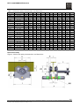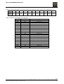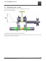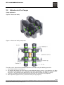
1
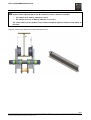
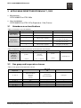
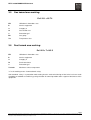
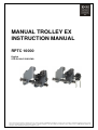
MANUAL TROLLEY EX
INSTRUCTION MANUAL
RPTC 10000
English
STD-R-KHA-F-CQD-ENG
This document and the information contained herein, is the exclusive property of R&M Materials Handling, Inc., and represents a non-public, confidential and proprietary trade secret that
may not be reproduced, disclosed to third parties, altered or otherwise employed in any manner whatsoever without the express written consent of R&M Materials Handling, Inc.
Copyright © (2010) R&M Materials Handling, Inc. All rights reserved.
RPTC 10000 MANUAL/EN/07.30.10
m
m
CAUTION: Read the instructions supplied with the product before installation and
commissioning.
CAUTION: Keep the instructions in a safe place for future reference.
TABLE OF CONTENTS
1
INTRODUCTION ........................................................................................................................................ 3
1.1
Foreword ............................................................................................................................................. 4
1.2
Warranty .............................................................................................................................................. 4
1.3
Minimum charges ................................................................................................................................ 4
1.4
Claims for damage in shipment........................................................................................................... 4
2 MANUAL TROLLEYS ................................................................................................................................ 5
2.1
What not to do ..................................................................................................................................... 5
2.2
What to do ........................................................................................................................................... 5
2.3
General information ............................................................................................................................. 6
2.3.1
Acceptance of the material .......................................................................................................... 6
2.3.2
Installation .................................................................................................................................... 6
2.4
Presentation ........................................................................................................................................ 8
2.4.1
Brief description of manual gantry crab ....................................................................................... 8
2.4.2
Characteristics and dimensions ................................................................................................... 8
2.5
Setting of the axle "no rock" .............................................................................................................. 12
2.6
Adjustment of the flanges .................................................................................................................. 13
2.7
Assembly on the track ....................................................................................................................... 15
3 APPLICABLE DIRECTIVES FROM JULY 1, 2003 ................................................................................. 16
3.1
Hazardous area classifications ......................................................................................................... 16
3.2
Gas group and temperature classes ................................................................................................. 16
3.3
ATEX label: ....................................................................................................................................... 17
3.4
Conformity to the ATEX Directive: .................................................................................................... 17
3.5
Gas hazard area marking: ................................................................................................................. 18
3.6
Dust hazard area marking: ................................................................................................................ 18
3.7
Technical installation and maintenance ............................................................................................ 19
3.7.1
Qualifications of installation & maintenance personnel ............................................................. 19
3.7.2
General maintenance ................................................................................................................. 19
2/19
This document and the information contained herein, is the exclusive property of R&M Materials Handling, Inc., and represents a non-public, confidential and proprietary trade secret
that may not be reproduced, disclosed to third parties, altered or otherwise employed in any manner whatsoever without the express written consent of R&M Materials Handling, Inc.
Copyright © (2010) R&M Materials Handling, Inc. All rights reserved.
RPTC 10000 MANUAL/EN/07.30.10
1
INTRODUCTION
m
m
CAUTION: Read the instructions supplied with the product before installation and
commissioning.
CAUTION: Keep the instructions in a safe place for future reference.
Before proceeding with the operation or maintenance of the equipment it is important that the operating and
maintenance personnel read this bulletin carefully in order to ensure the safe and efficient use of the
equipment.
Also, it is strongly recommended that the personnel responsible for the operation, inspection, and servicing
of this hoist, read and follow the Safety Standard ASME B30.16-1998 (or current revised edition). This
standard covers Overhead Hoists (under-hung) as promulgated by the American National Standards Institute
and is published by the American Society of Mechanical Engineers. Copies of this publication are available
from the Society at United Engineering Center, 345 East 47th St., New York, NY 10017.
If any instructions are unclear, contact the manufacturer or distributor of the equipment before attempting to
install or use the hoist.
R&M Materials Handling Inc
4501 Gateway Boulevard
Springfield, OH 45502
General Telephone:
937 - 328-5100
Toll Free Telephone (US):
800 - 955-9967
General Fax:
937 - 325-5319
3/19
This document and the information contained herein, is the exclusive property of R&M Materials Handling, Inc., and represents a non-public, confidential and proprietary trade secret
that may not be reproduced, disclosed to third parties, altered or otherwise employed in any manner whatsoever without the express written consent of R&M Materials Handling, Inc.
Copyright © (2010) R&M Materials Handling, Inc. All rights reserved.
RPTC 10000 MANUAL/EN/07.30.10
1.1
Foreword
This manual has been prepared to acquaint you of the procedures necessary for the installation, operation
and maintenance of the equipment you have purchased.
Proper use is important to the ultimate performance of this equipment. Careful study of and adherence to the
instructions will help ensure safe, dependable operation. It is also recommended that you keep this manual
readily accessible to operators as well as maintenance and safety personnel.
Information in this manual is subject to change without notice.
1.2
Warranty
All sales are subject to the R&M Standard Terms and Conditions of Sale and Product Warranty. Copies are
available upon request from R&M and are expressly incorporated by reference hereto.
1.3
Minimum charges
All orders for repair parts are subject to a minimum charge.
1.4
Claims for damage in shipment
All shipments are carefully inspected and are delivered to the carrier in good order. Upon receipt of shipment
caution should be exercised so that there is no loss or damage. If damage has occurred, refuse to accept the
shipment until the carrier makes the proper notation to that effect.
In the event of concealed loss or damage, notify the carrier immediately. By following these suggestions you
will encounter less difficulty collecting your claim.
4/19
This document and the information contained herein, is the exclusive property of R&M Materials Handling, Inc., and represents a non-public, confidential and proprietary trade secret
that may not be reproduced, disclosed to third parties, altered or otherwise employed in any manner whatsoever without the express written consent of R&M Materials Handling, Inc.
Copyright © (2010) R&M Materials Handling, Inc. All rights reserved.
RPTC 10000 MANUAL/EN/07.30.10
2
MANUAL TROLLEYS
2.1
2.2
What not to do
Do not set down the machine without having an adapted support to avoid damaging the sensitive
sides.
Do not let the machine drop.
Never modify the machine unless the constructor has studied and authorized the modification.
Never modify the values and adjustments of the safety components, outside the limits provided for in
the manual, or without the approval of the constructor.
Never try to repair or alter the machine (e.g., welding) without the authorization of the constructor or
a trained maintenance agent.
Do not let an unqualified person use the machine.
Never lift more than the maximum working load indicated on the machine. Shocks or accidental
collision of the load with objects can cause excess loads.
Never remove the hook safety catches.
Never use the machine to extract, loosen, or pull sideways.
Never use the machine to transport people.
Do not touch the moving components.
Do not operate the machine if your physical condition does not allow it.
Never use the machine when in bad repair (wear, deformation, etc.).
Never use suspect spare parts or parts whose origin is not known.
Never swing the load intentionally.
Do not subject the machine to brutal shocks.
Do not use the mechanical stops as a repetitive means of stopping.
Never distract the operator while the machine is being operated.
Never leave a suspended load hanging, unless necessary.
Do not use the machine for a purpose or in an area for which it is not intended.
Do not expose the machine to an aggressive atmosphere (temperature, acidity, etc.).
Do not use the safety components as operation components.
Do not use the controls needlessly (avoid inching, operating the buttons in a stop-start manner). This
can cause overheating and even damage to the machine.
Never pull the load slantwise. Make sure that the machine is vertical to the load before lifting.
Never transport a load with people nearby. Do not pass the machine, with or without a load, above a
person.
What to do
Handle the machine by its structure, or by the devices provided for this purpose, or in its original
packing.
Store the machine in its normal operating position (without load) away from aggressive atmospheres
(dust, humidity, etc.).
Make sure that the machine is always clean and protected from corrosion (lubrication, etc.).
The machine should be installed by a technician with the competence required.
Ensure the machine attaching structure is rigid.
Ensure that safety rules are followed (harness, clearance of work areas, posting of instructions to be
followed in the area, etc.).
Use the trolley between –10°C and + 50°C.
Comply with the distance between the trolley and the raceway.
Connect the feed cable directly to the supply terminal board in the electric box.
Set up an inspection program and record all maintenance operations for the machines, particularly
the brake, limit switches, fastening beam, etc.
Replace any element that is worn or may be defective.
The machine should be maintained regularly in accordance with the instructions in this manual.
Check the operation and adjustment of safety components (brake, travel limit, etc.) in conformity with
the user manual.
Regularly check the machine.
If a deformation or unusual wear is noted, the parts must be changed.
5/19
This document and the information contained herein, is the exclusive property of R&M Materials Handling, Inc., and represents a non-public, confidential and proprietary trade secret
that may not be reproduced, disclosed to third parties, altered or otherwise employed in any manner whatsoever without the express written consent of R&M Materials Handling, Inc.
Copyright © (2010) R&M Materials Handling, Inc. All rights reserved.
RPTC 10000 MANUAL/EN/07.30.10
2.3
Check that the assembly elements are correctly tightened.
Check that the steel cable strands supporting the control box fulfill their functions properly.
The components should only be replaced by original parts that are compatible with the type of
machine.
Before operation, ensure that the load is correctly fastened and installed. Make sure the load is
correctly balanced before moving it. Pay attention to the center of gravity of the load to be moved.
When moving the load, make sure it is sufficiently raised and distant from the surrounding machines
and other objects so as to avoid all obstacles during operation, ask for help if the volume of the load
prevents you from seeing above it.
Use the standards of ergonomics to use the trolley.
If manually moving the machine, push the load.
The prevention instructions to be carried out during different operations should be well known.
Use the material under normal working conditions (ambient temperature, atmosphere, etc.).
Material used outdoors should be protected as well as possible against bad weather conditions.
Notify the necessary people after a dangerous operation or if the machine seems problematic
(abnormal noise, abnormal behavior, etc.).
General information
2.3.1 Acceptance of the material
Carry out a visual inspection of the packing to ensure it is intact. If the package is not intact, issue the
appropriate notifications. Check that the trolley corresponds to your order.
2.3.2 Installation
The service life of a trolley depends upon how it is installed. It is essential that the instructions in this manual
are followed carefully for the installation, use, and maintenance of the machine. Any use contrary to the
instructions may be dangerous. In this case, the manufacturer will not accept any liability.
Do not use the machine without having read and understood the whole of the instruction manual. Always
keep the manual close to the machine, available to the operator and to the person responsible for
maintenance. Make sure safety rules are followed (harness, clearance of work area, posting of instructions to
be followed in the work area, etc.).
The trolley can be adapted to all runaway profiles. Couple or hook on the hoist after installation of the trolley.
m
CAUTION: Check the width of the runaway rail and adapt the spacing of the flanges of the
trolley as indicated in the tables
Ensure:
That the profile is secured.
That the profile is suitable to the loads to be supported.
That the dimensions are compatible with the trolley which is to be installed.
That the maximal deflection of the profile does not exceed 1/500 of the span under the dead loads and
the SWL.
That the longitudinal slope of the track does not exceed 0.3 %.
6/19
This document and the information contained herein, is the exclusive property of R&M Materials Handling, Inc., and represents a non-public, confidential and proprietary trade secret
that may not be reproduced, disclosed to third parties, altered or otherwise employed in any manner whatsoever without the express written consent of R&M Materials Handling, Inc.
Copyright © (2010) R&M Materials Handling, Inc. All rights reserved.
RPTC 10000 MANUAL/EN/07.30.10
Carry out:
1. Disassembly of the trolley
Remove the side plate on the counterweight side.
Position the trolley on the beam.
Refit the side plate.
Ensure that all nuts are correctly tightened.
2. Without disassembly of the trolley
Install the trolley on the profile, by the end.
Fit the travel limit stops (not provided) at the end of the runway.
Ensure that all nuts are correctly tightened.
On the curved profiles, the driving wheels should be positioned on the outside of the curve, preferably.
These points have to be checked after a repair, a maintenance operation or a long stop.
Curve radius:
250 kg / 500 kg
=
1m
1000 kg
=
1.5 m
2000 kg / 3000 kg
=
2m
5000 kg
=
3m
NOTE: Coupling part center must be located in the center of the beam.
Figure 1. Chain travel trolley
NOTE: VERY IMPORTANT! See side plate setting table.
7/19
This document and the information contained herein, is the exclusive property of R&M Materials Handling, Inc., and represents a non-public, confidential and proprietary trade secret
that may not be reproduced, disclosed to third parties, altered or otherwise employed in any manner whatsoever without the express written consent of R&M Materials Handling, Inc.
Copyright © (2010) R&M Materials Handling, Inc. All rights reserved.
RPTC 10000 MANUAL/EN/07.30.10
2.4
Presentation
The manual gantry crabs make it possible to suspend any type of lifting equipment provided with a hook,
lifting loads of 250 to 10,000 kg.
2.4.1 Brief description of manual gantry crab
The crab is comprised of:
2 flanges, in sheet steel
4 rollers mounted on ball bearings with detachable axles and rolling rims profiled to roll on any type
of iron monorail
1 cross-bar for hook or coupling, in steel, to ensure the bracing of the assembly.
2.4.2 Characteristics and dimensions
Push travel trolley
Figure 2. Push travel trolley characteristics and dimensions
8/19
This document and the information contained herein, is the exclusive property of R&M Materials Handling, Inc., and represents a non-public, confidential and proprietary trade secret
that may not be reproduced, disclosed to third parties, altered or otherwise employed in any manner whatsoever without the express written consent of R&M Materials Handling, Inc.
Copyright © (2010) R&M Materials Handling, Inc. All rights reserved.
RPTC 10000 MANUAL/EN/07.30.10
Table 1. Push travel trolley characteristics and dimensions
Capacity
[kg]
250
500
─
1000
─
2000
─
3000
─
5000
─
6300
─
7500
─
10000
─
12500
─
16000
─
20000
─
Beam width
[mm]
50 - 202
50 - 200
188 - 310
65 - 202
188 - 310
88 - 202
188 - 310
100 - 202
188 - 310
114 - 202
188 - 310
124 - 202
188 - 310
124 - 202
188 - 310
124 - 202
188 - 310
124 - 202
188 - 310
136 - 202
188 - 310
136 - 202
188 - 310
A
[mm]
284
303
411
326
425
340
448
356
464
375
484
394
502
394
502
400
506
408
514
472
578
472
578
B
[mm]
16
19
19
22
22
26
26
28
28
34
34
43
43
43
43
46
46
48
48
75
75
75
75
C
[mm]
32
32
32
39
39
42
42
49
49
60
60
68
68
68
68
70
70
70
70
92
92
88
88
ØD
[mm]
74
79
79
92
92
104
104
131
131
144
144
170
170
170
170
176
176
176
176
226
226
226
226
E
[mm]
60
62
62
82
82
98
98
146
146
161
161
175
175
175
175
187
187
185
185
283
283
277
277
F
[mm]
13
19
19
22
22
24
24
27
27
36
36
39
39
39
39
40
40
41
41
54
54
54
54
G
[mm]
170
185
185
225
225
272
272
322
322
362
362
411
411
411
411
442
442
442
442
555
555
555
555
H
[mm]
80
85
85
101
101
124
124
145
145
158
158
185
185
185
185
200
200
200
200
272
272
272
272
J
[mm]
194
210
210
249
249
296
296
346
346
386
386
436
436
436
436
466
466
466
466
579
579
579
579
ØK
[mm]
18
24
24
28
28
36
36
44
44
48
48
50
50
50
50
50
50
50
50
50
50
50
50
ØM
[mm]
15
20
20
22
22
28
28
28
28
35
35
43
43
43
43
45
45
50
50
64
64
68
68
ØN
[mm]
50
55
55
62
62
76
76
96
96
108
108
130
130
130
130
134
134
134
134
168
168
175
175
Chain travel trolley
Figure 3. Chain travel trolley characteristics and dimensions
9/19
This document and the information contained herein, is the exclusive property of R&M Materials Handling, Inc., and represents a non-public, confidential and proprietary trade secret
that may not be reproduced, disclosed to third parties, altered or otherwise employed in any manner whatsoever without the express written consent of R&M Materials Handling, Inc.
Copyright © (2010) R&M Materials Handling, Inc. All rights reserved.
RPTC 10000 MANUAL/EN/07.30.10
Table 2. Chain travel trolley characteristics and dimensions
A
B
C
ØD
E
F
G
H
J
ØK
ØM
ØN
P
Q
S
U
[kg]
Beam
width
[mm]
[mm]
[mm]
[mm]
[mm]
[mm]
[mm]
[mm]
[mm]
[mm]
[mm]
[mm]
[mm]
[mm]
[mm]
[mm]
[mm]
1000
65 - 202
326
22
39
92
82
22
225
101
249
28
22
62
146
76
40
160
188 - 310
425
22
39
92
82
22
225
101
249
28
22
62
146
76
40
160
Capacity
2000
3000
5000
6300
7500
10000
12500
16000
20000
88 - 202
340
26
42
104
98
24
272
124
296
36
28
76
146
92
38
157
188 - 310
448
26
42
104
98
24
272
124
296
36
28
76
146
92
38
157
100 - 202
310
28
49
131
146
27
322
145
346
44
28
96
37.5
114
38
58
188 - 310
418
28
49
131
146
27
322
145
346
44
28
96
37.5
114
38
58
114 - 202
326
34
60
144
161
36
362
158
386
48
35
108
37.5
126
47
60
188 - 310
434
34
60
144
161
36
362
158
386
48
35
108
37.5
126
47
60
124 - 202
344
43
68
170
175
39
411
185
436
50
43
130
80
154
46
68
188 - 310
452
43
68
170
175
39
411
185
436
50
43
130
80
154
46
68
124 - 202
344
43
68
170
175
39
411
185
436
50
43
130
80
154
46
68
188 - 310
452
43
68
170
175
39
411
185
436
50
43
130
80
154
46
68
68
124 - 202
350
46
70
176
187
40
442
200
466
50
45
134
80
154
46
188 - 310
458
46
70
176
187
40
442
200
466
50
45
134
80
154
46
68
124 - 202
358
48
70
176
185
41
442
200
466
50
50
134
59
154
45
65
188 - 310
466
48
70
176
185
41
442
200
466
50
50
134
59
154
45
65
136 - 202
416
75
92
226
283
54
555
272
579
50
64
168
73
197
78
78
188 - 310
522
75
92
226
283
54
555
272
579
50
64
168
73
197
78
78
136 - 202
416
75
88
226
277
54
555
272
579
50
68
175
73
120
60
78
188 - 310
522
75
88
226
277
54
555
272
579
50
68
175
73
120
60
78
10/19
This document and the information contained herein, is the exclusive property of R&M Materials Handling, Inc., and represents a non-public, confidential and proprietary trade secret
that may not be reproduced, disclosed to third parties, altered or otherwise employed in any manner whatsoever without the express written consent of R&M Materials Handling, Inc.
Copyright © (2010) R&M Materials Handling, Inc. All rights reserved.
RPTC 10000 MANUAL/EN/07.30.10
Figure 4. Hand chain length to unwind in order to move the load or the trolley over a distance of 1 m.
Load
[kg]
Chain
length
[m]
1000
1500
2000
3000
5000
6300
7500
10000
12500
16000
20000
3.4
3.4
3.4
4.5
4.5
5
5
5
5
9.5
9.1
Table 3. Wheel and handling chain capacities
Capacity
[kg]
wheel diameter
[mm]
handling chain
[mm x mm x mm]
1000
115
5 x 23.7 x 18
115
5 x 23.7 x 18
2000
115
5 x 23.7 x 18
115
5 x 23.7 x 18
3000
160
5 x 23.7 x 18
160
5 x 23.7 x 18
5000
160
5 x 23.7 x 18
160
5 x 23.7 x 18
6300
160
5 x 23.7 x 18
160
5 x 23.7 x 18
160
5 x 23.7 x 18
160
5 x 23.7 x 18
160
5 x 23.7 x 18
160
5 x 23.7 x 18
7500
10000
12500
16000
20000
160
5 x 23.7 x 18
160
5 x 23.7 x 18
160
5 x 23.7 x 18
160
5 x 23.7 x 18
160
5 x 23.7 x 18
160
5 x 23.7 x 18
11/19
This document and the information contained herein, is the exclusive property of R&M Materials Handling, Inc., and represents a non-public, confidential and proprietary trade secret
that may not be reproduced, disclosed to third parties, altered or otherwise employed in any manner whatsoever without the express written consent of R&M Materials Handling, Inc.
Copyright © (2010) R&M Materials Handling, Inc. All rights reserved.
RPTC 10000 MANUAL/EN/07.30.10
2.5
Setting of the axle "no rock"
Chain travel trolley 1000 kg (beam : 65 à 310), 2000 kg (beam : 88 à 310)
Figure 5. Axle setting dimension
This adjustment must be done when the trolley is put in place.
The dimension "H" between the lower face of the beam and the upper line of the axle is 1 mm. This value
may be adjusted to achieve best operation.
12/19
This document and the information contained herein, is the exclusive property of R&M Materials Handling, Inc., and represents a non-public, confidential and proprietary trade secret
that may not be reproduced, disclosed to third parties, altered or otherwise employed in any manner whatsoever without the express written consent of R&M Materials Handling, Inc.
Copyright © (2010) R&M Materials Handling, Inc. All rights reserved.
RPTC 10000 MANUAL/EN/07.30.10
2.6
Adjustment of the flanges
Trolley adjustment
Figure 6. Chain travel trolley
Figure 7. Chain travel trolley components
The trolley can be adjusted to accommodate different track widths using the following procedure:
1. Check width B of the track (Figure 7).
2. The distance B’ between the wheel flanges can be adjusted using the spacers (1) and washers (2). Make
sure that the suspension pin (3) is centered on the track. Depending on the tolerances of the washers
and spacers, the stacking can be different on the left side and on the right side (Figures 6 and 7).
3. In any case, provide at least one washer outside the flange (4), under the nut (5) (Figure 6)!
4. After adjustment, tighten the nuts (5) and reinsert the pins (6) (Figure 6).
13/19
This document and the information contained herein, is the exclusive property of R&M Materials Handling, Inc., and represents a non-public, confidential and proprietary trade secret
that may not be reproduced, disclosed to third parties, altered or otherwise employed in any manner whatsoever without the express written consent of R&M Materials Handling, Inc.
Copyright © (2010) R&M Materials Handling, Inc. All rights reserved.
RPTC 10000 MANUAL/EN/07.30.10
m
Caution: When adjusting dimension B’ between the rollers, add the track width:
•
For trolleys up to 2000 kg, add up to 3 mm C
•
For trolleys in excess of 3000 kg, add from 3 to 5 mm C
The values above are for guidance only. Clearance depends upon the tolerance and quality of
the track.
Figure 8. Chain travel trolley track adjustment dimensions
14/19
This document and the information contained herein, is the exclusive property of R&M Materials Handling, Inc., and represents a non-public, confidential and proprietary trade secret
that may not be reproduced, disclosed to third parties, altered or otherwise employed in any manner whatsoever without the express written consent of R&M Materials Handling, Inc.
Copyright © (2010) R&M Materials Handling, Inc. All rights reserved.
RPTC 10000 MANUAL/EN/07.30.10
2.7
Assembly on the track
At this stage, the distance between the wheel flanges is set. The trolley can be introduced through either end
of the hoist track. If this is not possible—for instance, if the mechanical stops or limit switches are already in
place—the trolley can also be installed through the lower flanges. In this case, remove the nuts on one side
of the trolley and move the flanges apart. Reassemble all components and ensure that dimension C is
correct (Figure 7).
Figure 9. Flanges being moved apart
Figure 10. Flanges being moved apart
m
Ensure that the suspension pin (3) is centered on the track (Figure 6).
15/19
This document and the information contained herein, is the exclusive property of R&M Materials Handling, Inc., and represents a non-public, confidential and proprietary trade secret
that may not be reproduced, disclosed to third parties, altered or otherwise employed in any manner whatsoever without the express written consent of R&M Materials Handling, Inc.
Copyright © (2010) R&M Materials Handling, Inc. All rights reserved.
RPTC 10000 MANUAL/EN/07.30.10
3
APPLICABLE DIRECTIVES FROM JULY 1, 2003
Manufacturer :
ATEX 94/09/EC or ATEX 100a
User (installation) :
ATEX 99/92/EC or ATEX 137a (England) or 118a (France)
3.1
Hazardous area classifications
Table 4. Hazardous area classification
Classification
Group 1 (mines)
Classification
Group 2 (surface)
Equipment category
Flammable substances
Comparison
M1
Methane, dust
Group 1
M2
Methane, dust
Group 1
1
Gases, vapors, fog, dust
2
Gases, vapors, fog, dust
3
Gases, vapors, fog, dust
Group 2
Z 0 (gases) / Z 20 (dust)
Group 2
Z 1 (gases) / Z 21 (dust)
Group 2
Z 2 (gases) / Z 22 (dust)
Table 5. Explosive atmosphere presence by hazard area classification
Category
Presence of
explosive
atmosphere
(per year)
3.2
1
2
Constant or for long
periods
Probable during normal
operation
(occasional)
> 1000 hrs
3
Rarely or for short
periods
Safe area
Practically never
< 10 hrs
10 <…< 1000 hrs
Gas group and temperature classes
Table 6. Gas group and temperature classes
Max. surface
temperature
T1 - 450° C
T2 - 300° C
T3 - 200° C
T4 - 135° C
T5 - 100° C
T6 - 85° C
II A
Methane
Monoxyde carbone
Ammoniac
Acetone
Toluene
Propane Butane
Gas
Acetaldehyde
─
─
Gas group
II B
IIC
Cyclopropane
Acide cyanhydrique
Hydrogene
Ethylene Butadiene
─
Diethyl ether
─
─
Acetylene
─
─
─
─
16/19
This document and the information contained herein, is the exclusive property of R&M Materials Handling, Inc., and represents a non-public, confidential and proprietary trade secret
that may not be reproduced, disclosed to third parties, altered or otherwise employed in any manner whatsoever without the express written consent of R&M Materials Handling, Inc.
Copyright © (2010) R&M Materials Handling, Inc. All rights reserved.
RPTC 10000 MANUAL/EN/07.30.10
3.3
ATEX label:
The following label identifies ATEX equipment suitable for the hazardous area defined by the specific
marking:
Figure 11. ATEX label
II 2 G c IIC T4
INERIS FILE NBR : 20372 / 08
AMBIENT TEMPERATURE
-20°C … +50°C
PLEASE REFER TO THE INSTRUCTIONS
According to ATEX Directive 99/92/EC, it is the user’s responsibility to verify the suitability of the ATEX
equipment to the hazardous area.
3.4
Conformity to the ATEX Directive:
INERIS, notified body and identified under number 0080, in accordance with article 9 of Council Directive
rd
94/9/EC of the 23 of March 1994, has acknowledged receipt of our technical file according to the procedure
described in article 8 b) ii) of the directive.
The technical documentation has been consigned by the INERIS notified body under the reference:
20372/08
17/19
This document and the information contained herein, is the exclusive property of R&M Materials Handling, Inc., and represents a non-public, confidential and proprietary trade secret
that may not be reproduced, disclosed to third parties, altered or otherwise employed in any manner whatsoever without the express written consent of R&M Materials Handling, Inc.
Copyright © (2010) R&M Materials Handling, Inc. All rights reserved.
RPTC 10000 MANUAL/EN/07.30.10
3.5
Gas hazard area marking:
Ex II 2 G c IIC T4
EX:
Utilization in hazardous area
II:
Surface equipment
2:
Category 2
G:
Gas hazard area
c:
Protection type*
IIC:
Gas group
T4:
Temperature class
3.6
Dust hazard area marking:
Ex II 2 D c T+135°C
EX:
Utilization in hazardous area
II:
Surface equipment
2:
Category 2
D:
Dust hazard area
c:
Protection type*
T+135°C:
Maximum surface temperature
*‘c’ in the marking means "Constructional safety"
Constructional safety is a protection mode stating that the mechanical design of the hoist has been made
according to standards to avoid any spark generation in normal operation and in regular maintenance of the
equipment.
18/19
This document and the information contained herein, is the exclusive property of R&M Materials Handling, Inc., and represents a non-public, confidential and proprietary trade secret
that may not be reproduced, disclosed to third parties, altered or otherwise employed in any manner whatsoever without the express written consent of R&M Materials Handling, Inc.
Copyright © (2010) R&M Materials Handling, Inc. All rights reserved.
RPTC 10000 MANUAL/EN/07.30.10
3.7
Technical installation and maintenance
3.7.1 Qualifications of installation & maintenance personnel
Only persons whose training includes instruction on the various types of protection involved, including
appropriate, periodic refresher training, should carry out installation and maintenance.
3.7.2 General maintenance
Repairs on Ex equipment are classified into two types:
Work on equipment in the hazardous area.
Work on equipment that can be removed from the hazardous area
Work in the hazardous area
The following must be clarified with the operator before starting work in the hazardous area:
Is there an explosion hazard in the working area?
Is there a poison hazard?
What visual and acoustic signals apply in case of danger?
Are there escape routes and how are they marked?
How is the equipment isolated from the mains supply and secured (warning sign and padlock)?
What hazard zone is present:
in the vicinity of the Ex equipment?
in the vicinity of the control equipment (on the ground for cranes)?
The customer is responsible for the use and safety of the installation during operation. Consequently, they
alone are qualified to answer the questions above in sufficient detail and, thus, determine whether work can
be carried out without risk.
Typically, the customer will issue a “hot work” permit in which the operator informs the technician that he may
work on the Ex installation and specifies the times when he may do so. This written permit is primarily
required for welding and other works that may cause a hazard (e.g., grinding), but also applies when
auxiliary equipment, such as a power drill, is used.
After the work—not including maintenance work—has been completed, the customer may demand an
installation certificate. The technician assumes significant responsibility for this work because the customer is
not obligated to have the electrical installation inspected further by an Ex expert before commissioning.
Modifications to Ex equipment affecting Ex protection may not be performed by the technician. If such
modifications are necessary, the equipment or the installation must be inspected by an Ex expert. The
acceptance test is confirmed by an expert's report.
If you are uncertain about any issues that may arise during a repair, always seek guidance from your senior
manager or local specialist.
If you are forced by a customer for reasons of urgency to perform a modification or installation that does not
comply with regulations, please ensure that the customer signs a certificate with the following wording:
"The modification on equipment __________was ordered by me_________for operational reasons, despite
the technician’s indication that the condition of the equipment no longer complies with regulations. It was
pointed out that the equipment must be returned to a serviceable condition as soon as possible."
Work outside the hazardous area
If practical, equipment should be moved to a safe area before commencing work. If such relocation is
possible, observe all safety precautions when dismantling and transporting the equipment. This includes
vehicles moving equipment from the hazardous area to a non-hazardous area and vice versa.
19/19
This document and the information contained herein, is the exclusive property of R&M Materials Handling, Inc., and represents a non-public, confidential and proprietary trade secret
that may not be reproduced, disclosed to third parties, altered or otherwise employed in any manner whatsoever without the express written consent of R&M Materials Handling, Inc.
Copyright © (2010) R&M Materials Handling, Inc. All rights reserved.