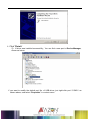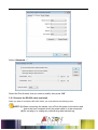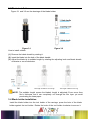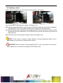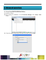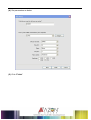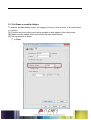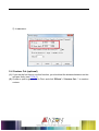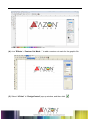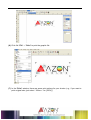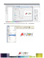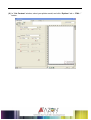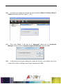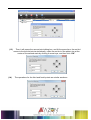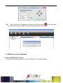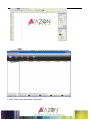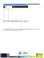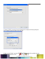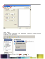
1
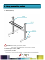
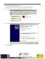
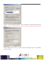
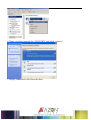
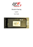
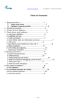
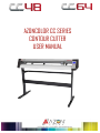
AZONCOLOR CC SERIES
CONTOUR CUTTER
USER MANUAL
V.1.1 SEPT 2014
V.1.1 SEPT 2014
1. Important Information
Before you use the cutting plotter, please make sure that you have read
the safety precautions and instructions below.
Notes, Cautions, and Warnings
3
4
3. Set up your cutting plotter
3.1 Stand (optional)
CAUTION: Must use M5*45 screws with washers.
Must use M5*10 screws to fix the cutting plotter to the stand.
3.2 Connect your cutting plotter
3.2.1 Connect the AC cable
Connect the AC cable to the AC connector on the plotter and to the electrical outlet.
5
3.2.2 Connect the USB cable (optional)
If you want to use the USB cable, you have to install the USB driver.
1.Find the following files from the CD, Double-click CDM20814_Setup.exe
2. connect USB cable with computer,it will display ‘ Found New Hardware’ as follow window.
3.Click “NEXT”
6
4. Click “Finish”
5 .If driver was installed successfully,You can find a new port in Device Manager,
○
shown as below
if you want to modify the default port No. of USB driver, just right-click port(COM3)as
shown above, and select “Properties” in context menu.
7
Select “Advanced…”,
Select the Port Number. that you want to modify, then press “OK”
3.2.3 Connect the RS-232 cable (optional)
When you want to connect the RS-232C cable, you must observe the following notes
NOTE: (1) When connecting the cables, turn off first the power to the device and
that to the host computer which the power cable is to be connected.
(2) Do not plug in or unplug any cable during data transferring.
8
3.3 Blade installation
Figure 3-1 and 3-2 are the drawings of the blade holder.
Figure 3-1
How to install a blade
Figure 3-2
(1) Remove the blade sheath by rotating it.
(2) insert the blade into the hole of the blade handle.
(3) Adjust the blade tip to suitable length by rotating the adjusting knob and blade sheath
clockwise or count-clockwise.
OK
The length of blade is not enough
The length of blade is too long
NOTE: The suitable length means the blade’s length is adjusted 0.1mm more than
film’s thickness and it can completely cut through the film layer yet avoid
penetrating the base paper.
3.4 Blade holder installation
Install the blade holder into the tool holder of the carriage, press the brim of the blade
holder against the tool holder. Rotate the knob of the tool holder clockwise to secure it.
9
3.5 loading a sheet
Either a piece of sheet or a roll of sheet can be loaded on the plotter.
(1)
(2)
(3)
(4)
Figure 3-3
Figure 3-4
Lift the lever to rise the pinch rollers. (see Figure 3-3)
Load the sheet and slide to under the pinch rollers form either the front side or backside.
The alignment ruler on the platen will help you to adjust the sheet precisely.
Slide the pinch rollers manually to the proper position. Be sure the pinch rollers must be
positioned above the steel axes. The red mark on the top trail will remind you where the
steel axes are.
Press the lever to lower down the pinch rollers.(see Figure 3-4)
NOTE: If you want to cutting a sheet without a reversed adhesive paper (like a
pasteboard),You should use a sticker sheet under it.
CAUTION: Move the pinch roller by applying force at the rear portion of the pinch
roller support. Do not move it by holding its front rubber roller.
10
5. Advanced operations
5.1 Cut in FlexiSTATER AZONColor Edition
(1) Install the software
(2) After finishing the installation, run the Production Manager, Click “Setup”->”Add
setup…”.
(3) Select the names of brand and model upon your plotter, and click “Next”
11
(4) Set parameters as below:
(5) Click “Finish”.
12
5.3 Cut 5mm or smaller letters
To achieve the best quality output, we suggest you use a narrow sheet. If use wide sheet,
you should:
(1) Position two pinch rollers as close as possible to both edges of the cutting area.
(2) Make sure the loaded sheet is placed the flat with equal tension.
(3) Set parameters as below:
1 In Flexi:
○
13
2 In ARTCUT:
○
5.4 Contour Cut (optional)
(1) If you are the first time to use this function, you should set the distance between red dot
and pen firstly (see P17-4.5 ).
(2) Create or open a graphic file in Flexi, and click “Effects”->”Contour Cut…” to create a
contour.
14
(3) A djust related parameters in “DesignCentral” pop-up window, and then click
15
(4) Click “Effects”->“Contour Cut Mark…” to add a contour cut mark for the graphic file.
(5) Select “4 Point” in “DesignCentral” pop-up window, and then click
16
.
(6) Click file “File” -> “Print” to print the graphic file.
(7) In the “Print” window, there are some print options for your choice (e.g., if you want to
print original size, just select “100cm = 1m [100%]”)
17
(8) Load the printed sheet on the plotter, and click file “File” -> “Cut Contour…”
18
(9) In “Cut Contour” window, select your plotter model, and click “Options” tab -> “Edit…”
button.
19
(10)
It will pop up a dialog box, please set the parameters Offset X 0.00mm, Offset Y
0.00mm as below, and click “Apply”-> “OK”.
(11)
Then click “Send”, It will pop up a “Alignment” dialog box in “Production
Manager” window, select “Interactive alignment (Manual)”,and click “OK”.
(12)
It will popup the first point dialog box, make the red dot of the plotter aim at the
center of the mark by clicking 4 arrow keys, and then click “OK”.
20
(13)
(14)
Then it will popup the second point dialog box, and At the same time, the red dot
moves to the second point automatically, make the red dot of the plotter aim at the
center of the second mark by clicking 4 arrow keys, and then click “OK”.
The operations for the third and fourth points are similar as above.
21
(15)
Then it will pop up a dialog box as blow, press Origin button
on control panel
of plotter. And then press “OK”, the plotter will perform the contour cut.
5.5 Wireless control (optional)
How to use WIFI with Flexi soft
1. Run the Flexi Design software to access AZONColor CC Series features.
22
2. Click the
cut icon to display a cutter checkbox below the cutter listing
3. Click ”setup” and then select “add setup”
23
4. Select AZONColor and your model from the available dropdown menus. After you select
your AZONColor CC series product, click “NEXT”
24
6. Choose “TCP/IP” connection from the dropdown list to display the following dialog box.
Input IP address and port number, then click “OK”.
8. After you click “Finish”, your new AZONColor CC Series cutter will be available from the
Cut/Plot device dropdown menu.
25
.
WiFi Setup
1.Open “network connections”, click right-button of mouse on “wireless Network
Connection”, click “properties”
2. Select “Internet Protocol (TCP/IP)”,click26“properties”
3.Select “use the following IP address” ,Input IP address and subnet mast and default
gateway. (caution: subnet mast must be 255.255.255.0, default gateway must be
192.168.0.1.)
4.click “ok”
5. click right-button of mouse on “wireless Network Connection”,click “view Available
wireless networks”
27
6.Chose a wireless network for “WIFI-XXX”,and click “connect”
7. display connected is Ok,Close this Box,
28
Find More Information and Resources.
Please visit our Website: http:/www.azonequipment.com/
If you have any questions, please contact us or email to info@ azonequipment.com
Information in this document is subject to change without notice.
Reproduction of these materials in any manner whatsoever without the written permission of
AZONColor lnc. is strictly forbidden.
29