1
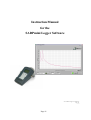
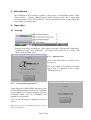
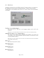
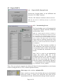
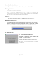
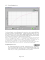
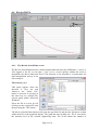
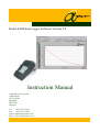
Model SADPmini Logger Software Version 2.8
Instruction Manual
Alpha Moisture Systems
Alpha House
96 City Road
Bradford
BD8 8ES
England
Tel: +44 1274 733100
Fax: +44 1274 733200
Email: [email protected]
Web: www.amsystems.co.uk
Page ii
Instruction Manual
for the
SADPmini Logger Software
1225 SADPmini Logger User Manual.doc
Issue 14.0
1/3/12
Page iii
Index
1
2
3
SADPMINI SPECIFICATION ............................................................................................................. 1
PC SPECIFICATION.......................................................................................................................... 1
SOFTWARE INSTALLATION ............................................................................................................. 1
3.1
3.2
4
5
6
UN-INSTALLATION OF SOFTWARE .................................................................................................. 1
INTRODUCTION ............................................................................................................................... 2
OPERATION ..................................................................................................................................... 2
6.1
6.1.1
6.1.2
6.1.3
6.2
6.2.1
6.2.2
6.3
6.3.1
6.3.2
6.4
6.4.1
6.5
7
AUTOMATIC INSTALLATION ................................................................................................................. 1
MANUAL INSTALLATION ...................................................................................................................... 1
STARTUP .............................................................................................................................................. 2
Splash Screen.................................................................................................................................. 2
Connection Pop-up Screen.............................................................................................................. 2
Main Screen .................................................................................................................................... 3
EXPORT DATA .................................................................................................................................... 4
Export DATA Pop-up Screen ......................................................................................................... 4
Downloading Screen....................................................................................................................... 4
EXTERNAL LOG................................................................................................................................... 5
External LOG Pop-up Screen ......................................................................................................... 5
External Logging Screen ................................................................................................................ 6
REVIEW DATA .................................................................................................................................... 8
The Review Stored Data screen...................................................................................................... 8
DISABLING POP-UPS ........................................................................................................................... 10
CABLES AND INTERFACES ............................................................................................................ 10
7.1
7.2
RS232 TO RS485 INTERFACE ............................................................................................................. 10
USB TO RS485 INTERFACE ................................................................................................................ 10
Page iv
1 SADPmini Specification
SADPmini Logger Software Version 2.8 requires that the SADPmini being
communicated with is running version 5.3 firmware or higher. If the SADPmini has a
lower firmware version then obtain SADPmini Logger Software Version 1.32.
2 PC Specification.
The PC should be running Windows XP, Vista or 7. The PC screen resolution should be
set to a minimum of 1024 x 768 pixels.
3 Software Installation
If applicable, make sure you are logged on with sufficient privileges to install new
software.
3.1 Automatic Installation
1.
2.
3.
4.
Place the CD into the CD drive.
The CD will automatically start the Installation Wizard
Follow the on-screen instructions
Use the default installation directory of c:\sadpmini 2.8
3.2 Manual Installation
If the Software does not automatically install follow the sequence below: 1.
2.
3.
4.
5.
6.
7.
8.
9.
Place the CD into the CD drive.
Press the ‘Start’ button and select the ‘Run’ option.
Press the ‘Browse’ button.
Select the CD from the ‘Look in’ pull down menu.
Highlight the Setup.exe file and press the ‘Open’ button.
Press the ‘OK’ button.
The Installation wizard will then take you through the installation process.
Follow the on screen instructions
Use the default installation directory of c:\sadpmini 2.8
Files installed in the SADPmini folder: • data\lvtime.dll
• alpha.ico
• SADPmini.exe
• SADPmini.ini
• SADPmini.set
4 Un-installation of Software
To un-install the SADPmini Logger program simply follow the instructions in ‘Section 3
Software Installation’ from 1 to 4. The installation wizard will automatically remove the
software from the PC.
Page 1 of 10
5 Introduction
The SADPmini Logger software consists of three parts, a downloading facility called
‘Export DATA’, a remote logging facility called ‘External LOG’ and a stored data
reviewing facility called ‘Review DATA’. See the associated sections in this manual for
more details on each operation.
6 Operation
6.1 Startup
Start the program by pressing the ‘Start’ button, selecting ‘All Programs’ followed by
‘SADPmini Logger’ and ‘SADPmini’. The splash screen shown in 6.1.1 below will
appear as the program starts.
6.1.1
Splash Screen
Click on the OK button to continue to the
next screen.
The radio button in the bottom left hand
corner will be explained in the section
‘Disabling Pop-ups’.
6.1.2
Connection Pop-up Screen
Using either the USB to RS485 Interface or the
Serial to RS485 Interface connect the SADPmini
to the logging PC or laptop computer, using the
associated cables, (See the SADPmini user
manual for more details).
Click on the OK button to continue to the next
screen.
Note: See the section on ‘Disabling Pop-ups’ to prevent
this screen appearing.
Page 2 of 10
6.1.3
Main Screen
It should be noted that before the SADPmini and the PC logging software can communicate
the SADPmini needs to be put into communication mode – to achieve this activate the
‘Logging Menu’ on the SADPmini and select the ‘PC Comms’ function. (See the SADPmini
user manual).
Com Port: selector (default setting 1)
This control sets the ‘COM Port’ on the logging computer used to talk to the
SADPmini.
Note: Refer to your Windows Manual for information on how to find out your COM port setting.
SADPmini Unit Address: selector (default setting 1)
This control sets the address that the SADPmini will respond to (see section 9.2.9
‘Unit Address’ in the ‘Model SADPmini Instruction Manual’ for instructions on how
to set the SADPmini address).
Note: Failure to set these variables correctly will result in the communications between the SADPmini
and the logging computer failing.
EXIT button:
This control aborts the PC software.
Export DATA button:
See Section 6.2.
External LOG button:
See Section 6.3.
Review DATA button:
See Section 6.4.
Page 3 of 10
6.2 Export DATA
6.2.1
Export DATA Pop-up Screen
Activate the ‘Logging Menu’ on the SADPmini and
select the ‘PC Comms’ function.
Click the ‘OK’ button to continue to the next screen.
Note: See the section on ‘Disabling Pop-ups’ to prevent this
screen appearing.
6.2.2
Downloading Screen
The Downloading screen will automatically
communicate with the attached SADPmini,
and list all the TAGs.
Note: If a window appears reporting a Timeout or
Error Message and all buttons are grayed out except
the ‘Exit’ button, the SADPmini logger software is
not communicating with the SADPmini. Press the
‘Exit’ to return to the ‘Main Screen’. Ensure that the
correct cables are connected, and that the correct
‘Address’ and ‘Com Port’ settings have been set and
that the ‘PC Comms’ function has been activated on
the SADPmini.
There are 20 TAG locations available in
each SADPmini. Each location can store up
to 20 separate blocks of data. Downloading
a TAG automatically downloads the data
blocks.
Each TAG is saved to an automatically
created and named .MST file in the
SADPmini directory. The filename created
is based upon the TAG name. If multiple
files are to be saved using the same TAG
name the software automatically appends a
‘_#’ discriminator to the end of the filename
e.g. ‘DEFAULT TAG_2.MST’.
These files can easily be imported into Microsoft Excel for data manipulation, as the format
used in creating the files is CSV (Comma Separated Values).
Select tags rocker switches: (default OFF)
These controls are used to select the data that is to be downloaded.
When the switch is Yellow, the associated TAG data will be
downloaded when the ‘Download selected tags’ button is pressed.
Page 4 of 10
Select all and De-select all buttons:
These controls are used to turn all the rockers switches to ON or OFF.
Read tag names button:
NOT USED IN NORMAL OPERATION
Used to re-read the SADPmini TAGs. This is useful for re-establishing the
communications link between the computer and the SADPmini when the SADPmini
has been used for other functions, which will lose the link.
Exit button:
This control returns the PC software to the Main screen (See section 6.1.3)
Download selected tags button:
This control starts the process of downloading the required TAGs. After the button is
pressed, an indicator appears that calculates the number of samples that are to be
downloaded. A progress bar then appears that indicates the progress of the download.
Once all the data has been downloaded to the PC returns to the Main Screen 6.1.3.
6.3 External LOG
6.3.1
External LOG Pop-up Screen
Activate the ‘Logging Menu’ on the SADPmini and
select the ‘PC Comms’ function.
Click the ‘OK’ button to continue to the next screen.
Note: See the section on ‘Disabling Pop-ups’ to prevent this
screen appearing.
Page 5 of 10
6.3.2
External Logging Screen
The External Logging screen will automatically communicate with the attached SADPmini
and update the graphical and digital displays. The graph has auto-scaling axis. The Y-axis
shows the moisture level in the current engineering units of the SADPmini. The X-axis shows
the number of readings and the interval between each reading. Approximately 8000 readings
can be displayed on the graph before the display automatically scrolls
Note: If a window appears reporting a Timeout or Error Message and all buttons are grayed out except the
‘Exit’ button, the SADPmini logger software is not communicating with the SADPmini. Press the ‘Exit’ to
return to the ‘Main Screen’. Ensure that the correct cables are connected, that the correct ‘Address’ and ‘Com
Port’ settings have been set and that the ‘PC Comms’ function has been activated on the SADPmini.
Note: If the Logging LED flashes Green for an instant before turning back to Red when the ‘Logging’ button is
pressed, the ‘Com Port’ selected is incorrect. Press the ‘Exit’ button and return to the ‘Main Screen’.
Graph Manipulation Palette:
The graph manipulation palette enables the graphical display to be manipulated in
various ways. Before using this palette, it is recommended that the logging of new
data be stopped because new data points cause the graphical display to refresh in the
default form, over writing any manipulation that had been performed.
Page 6 of 10
The top three Icons enable specific areas of the graphical
display to be enlarged. The area to be enlarged is selected by
depressing the left mouse button and dragging the cursor.
The graphical display is then redrawn. The Bottom left Icon
performs an undo function. The other 2 Icons are zoom in
and out functions activated by pressing the left mouse button.
Digital Display indicator:
This displays the last data point value in and the associated engineering units.
Interval/min selector: (default 0.1)
This control sets the delay between subsequent data points in minutes. The value
increments and decrements in 0.1-minute steps. It is also possible to set the delay
period by highlighting the current value and typing a replacement value.
File Path controller: (default c:\SADPmini 2.7\test.txt)
The file logging function is selected by clicking
on the LED. The LED turns light green and the data points are automatically written
to the default file ‘test.txt’. Clicking on the LED again turns the LED dark green and
stops writing data to file.
Note: Data points are always appended to this file. The file is never overwritten. It is therefore
recommended that if this facility is required that the file is deleted before starting to log, as if the file
does not exist the program will create it.
The test.txt file can easily be imported into Microsoft Excel for data manipulation, as
the format used in creating the file is CSV.
Logging button:
Used to start and stop the logging of data points from the SADPmini. The LED turns
green for logging and red for not logging.
Note: It is advisable to stop logging before performing graph manipulation. It is also required to stop
logging before exiting the External Logging function.
Exit button:
This control returns the PC software to the Main screen (See section 6.1.3)
Note: This button is greyed out when logging is in progress. Stop logging to activate the ‘Exit’ button.
Page 7 of 10
6.4 Review DATA
6.4.1
The Review Stored Data screen
The Review Stored Data function enables downloaded data from the SADPmini (“*.mst”) or
files logged to the PC in real time (“*.txt”) to be viewed quickly without the need to
manipulate the data in Microsoft Excel. This function is not intended as a replacement for
data manipulation merely as an
aid to analysis.
File selector panel:
This panel appears when the
function is first run and
whenever the ‘Select File’
button is pressed. It operates in
the same way as a normal File
selector panel within ‘Microsoft
Windows’.
Select the file to review by left
clicking on the required file and
then pressing the ‘OK’ button.
The Review Stored Data function will open the specified file and plot the first block of data
within that file to the graphical display. The graph has auto-scaling axis. The Y-axis shows
the moisture level in the selected engineering units. The X-axis shows the number of
Page 8 of 10
readings, pressure, when the readings were taken and the start and finish time of the test. A
maximum of 12800 readings can be displayed on the graph. It is therefore strongly
recommended that the logging time interval is chosen so that during the data logging
process the number of readings stored does not exceed 12800.
Graph Manipulation Palette:
The graph manipulation palette enables the graphical display to be manipulated in
various ways.
The top three Icons enable specific areas of the graphical
display to be enlarged. The area to be enlarged is selected by
depressing the left mouse button and dragging the cursor.
The graphical display is then redrawn. The Bottom left Icon
performs an undo function. The other 2 Icons are zoom in
and out functions activated by pressing the left mouse button.
Digital Display indicators:
The following information is read from the selected file and displayed in four digital
display indicators, located above the graphical display
TAG Name:
Sample Rate (mins):
Date:
Start Time:
Print button:
This button will automatically send a printout to the computers default printer. There
is no printer setup function so the printout will conform to the printers default
settings. i.e. the printout will be in portrait if that is the default setting of the printer.
Select File button:
This button brings up the File Selector panel.
Block Indicator LEDs:
These controls are disabled and grayed out when reviewing a real time file
There are 20 LEDs, one for each permissible block of data that can be
stored under each TAG name on the SADPmini. When a file is opened, the
LEDs indicate as follows:
Light Green
Blue
–
–
Dark Green
–
Block containing data.
Block containing data and currently selected
for graphing.
Block containing no data.
Page 9 of 10
Block Selector buttons:
The 2 small buttons located at the top left hand side of the Block Indicators are used to
select the data block to be graphed. The blue LED signifies the data block that is
currently plotted. The block selector buttons move the selected block up or down.
Note: Only blocks containing data can be selected for graphing
Exit button:
This control returns the PC software to the Main screen (See section 6.1.3)
6.5 Disabling Pop-ups
To disable the information pop-up screens simply select the ‘Disable Pop-up’ radio button on
the Splash screen (see section 6.1.1). This will prevent the information panels from
appearing. It is recommended that this process is not used until the user is completely
confident with the physical operation of the SADPmini logging software and the Model
SADPmini.
The screens disabled are:
Initial Pop-up Screen (see section 6.1.2).
Export DATA Pop-up Screen (see section 6.2.1).
External LOG Pop-up Screen (see section 6.3.1).
The pop-up screens can be re-enabled at any time by de-selecting the radio button on the
splash screen (see section 6.1.1).
7 Cables and Interfaces
There are 2 types of interface that can be used with the SADPmini and SADPmini Logging
software.
7.1 RS232 to RS485 Interface
The Interface unit INT007 has two 9-way ‘D’ type connectors. The connector marked
with a ‘B’ connects to a PC or Laptop serial Port using a 2.0m serial cable (Part No:
CAB029). The connector marked with a ‘S’ connects to the SADPmini using a 1m
special cable (Part No: CAB032).
7.2 USB to RS485 Interface
The Interface unit INT008 has a 9-way ‘D’ type connector and a USB connector. The
USB connects to a PC or Laptop USB Port using a 1.8m USB cable (Part No:
CAB031). The ‘D’ type connects to the SADPmini using a 1m special cable (Part No:
CAB033).
Note: The drivers for the USB Interface are supplied on the included CD.
Page 10 of 10