1
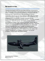
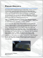
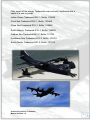
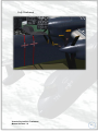
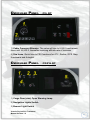
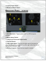
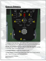
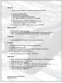
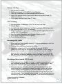
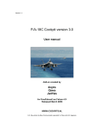
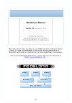
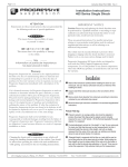
R3Y Tradewind USER MANUAL Virtavia Pty Ltd R3Y Tradewind Manual Version 1.0 0 Introduction Originally developed to fulfill the long-range maritime reconnaissance role, the Convair XP5Y-1 was noteworthy for its high-speed blended-hull design, intended to overcome the aerodynamic drag associated with flying boat hulls. Powered by four 5250 shp Allison XT-40-A-4 turboprops, it flew for the first time on April 18, 1950. Changes in USN requirements led to a redesign of the aircraft to the transport role. Redesignated R3Y-1 Tradewind, 11 aircraft were built. Several modifications were incorporated into the new R3Y-1 including increased horsepower T-40-A-10 engines, new nacelles, shorter airscrew driveshafts and tailpipes, and V-shaped float struts. Convair later redesigned the nose and added a large hinged door at the bow. This new version was designated R3Y-2 and flew on October 22, 1954. A last attempt at salvaging the project resulted in a refuelling tanker conversion, but this was not enough to save the Tradewind. All were scrapped in 1959. The Virtavia R3Y Tradewind is a fully 'native' FSX release, including the now standard technologies such as self shadowing, bloom effects, and bump mapping. Virtavia Pty Ltd R3Y Tradewind Manual Version 1.0 1 Installation An easy installation is provided by way of an auto-installer , the Tradewind will be installed to the default FSX folder structure. The install path can be edited in the Installer Dialogue to reflect a custom installation path such as E:Games\FSX\ for example. Extras such as this manual will be installed into FSX/Virtavia. A start menu entry will also be made, with an uninstaller should you ever wish to remove the product. Please see the ‘Package Contents’ section for more details on what is included in this package. Credits Exterior model – Virtavia Textures – Dan Dunn of Pixl Creative Interior model - Virtavia Gauges – Herbert Pralle/Virtavia Animation coding – Virtavia Flight Dynamics - Mitch London Engine Sounds - Virtavia Manual - Virtavia Testing - Frank Safranek, Mitch London, Virtavia Recommended reading : Naval Fighters 34, by Steve Ginter, ISBN 0-942612-34-5 Virtavia Pty Ltd R3Y Tradewind Manual Version 1.0 2 Support Should you experience difficulties or require extra information about the Virtavia R3Y Tradewind, please e-mail our technical support on [email protected] Copyright Information Please help us provide you with more top quality flight simulator models like this one by NOT using pirate copies. The flight simulation industry is not very profitable and we need all the help we can get. Please - help us grow by buying a legitimate copy. These files may not be copied (other than for backup purposes), transmitted or passed to third parties or altered in any way without the prior permission of the publisher. The source code for this product is closed. No modifications or reverse engineering may be carried out without prior consent from Virtavia Pty Ltd. All rights reserved – copyright Virtavia Pty Ltd 2013 Virtavia Pty Ltd R3Y Tradewind Manual Version 1.0 3 Package Contents The Virtavia R3Y Tradewind package contains both variants, the R3Y-1 ‘Cruiser nose’ (named because of the similarity of the cockpit area shape to a popular automobile of the time) and the R3Y-2 ‘Bowloader’ version with the hinged nose for roll-on roll-off cargo. A further subversion of the R3Y-2 is included, the aerial refuelling tanker (‘KR3Y-2’ is an unofficial designation by Virtavia). The tanker differs from the regular R3Y-2 only in that it has underwing refuelling pods. In all, 11 Tradewinds were built at Convair’s San Diego plant between 1950 and 1955. The six R3Y-1 aircraft had BuNo’s 128445 - 128450, the five R3Y-2 Bowloaders had BuNo’s 131720 – 131724. On 17th December 1953, actress Esther Williams christened the first Convair Tradewind (BuNo 128445) with a champagne bottle containing actual samples of water collected from many seas and oceans of the world – Arabian Sea, North & South Atlantic, Baltic Sea, Black Sea, Caribbean Sea, China Sea, Coral Sea, Indian Ocean, Mediterranean Sea, North & South Pacific Ocean, Pearl Harbor, San Francisco Bay and the Tasman Sea. The first flight was on 25th February 1954. The delivery flight of the fourth R3Y-1 (BuNo 128448) from San Diego to NAS Patuxent River, MD, was a record-breaking transcontinental flight, covering the 2,400 miles in only 6 hours. The first R3Y-2 flight took place on 22nd October 1954. The final Tradewind delivery took place on 31st March 1956, when R3Y-2 BuNo 131724 landed at VR-2 Squadron’s Alameda base. Virtavia Pty Ltd R3Y Tradewind Manual Version 1.0 4 Only seven of the eleven Tradewinds were actually christened with a name of a sea or ocean : Indian Ocean Tradewind R3Y-1, BuNo. 128446 Coral Sea Tradewind R3Y-1, BuNo. 128448 China Sea Tradewind R3Y-1, BuNo. 128449 South Atlantic Tradewind R3Y-1, BuNo. 128450 Arabian Sea Tradewind R3Y-2, BuNo. 131722 Caribbean Sea Tradewind R3Y-2, BuNo. 131723 South Pacific Tradewind R3Y-2, BuNo. 131724 Virtavia Pty Ltd R3Y Tradewind Manual Version 1.0 5 R3Y-1 ‘Indian Ocean Tradewind’ Notable achievments : 2nd Tradewind built. Set Honolulu to Alameda record on 18th Oct 1956. On 24th January 1958, damage caused by a sheared propeller required an emergency landing in San Francisco Bay. The landing was successful but the aircraft was uncontrollable and taxied at speed into a sea wall. The aircraft’s hull was damaged beyond repair. After this accident, all Tradewinds were grounded and never flew again. R3Y-1 ‘Coral Sea Tradewind’ Notable achievments : 4th Tradewind built. 1st delivered to USN. Record-breaking transcontinental flight 24th February 1954. Virtavia Pty Ltd R3Y Tradewind Manual Version 1.0 6 R3Y-2 ‘Caribbean Sea Tradewind’ Notable achievments : 10th Tradewind built. Lost No.1 prop June 1957, made emergency landing at Alameda. R3Y-2 ‘South Pacific Tradewind’ Notable achievments : 11th and last Tradewind built. Virtavia Pty Ltd R3Y Tradewind Manual Version 1.0 7 Exterior Model The exterior model has all the usual animations such as ailerons, elevators and flaps. There are no speedbrakes fitted to the R3Y. Exits and Bowloader nose Shift-E : R3Y-1 – main passenger doors (nose left side, fuselage rear both sides) R3Y-2 – crew ladder (near front of cargo hold, inside), main passenger doors (fuselage rear, both sides) Shift-E+2 : Both variants – cargo hold door (rear, left side) Shift-E+3 : R3Y-1 – anchor compartment door (front, left side) R3Y-2 – hinged nose and cargo ramps Shift-E+4 : R3Y-1 – anchor compartment door (front, right side) R3Y-2 – refuelling pods and drogues (KR3Y-2 only) Access steps Not an animation as such, the steps will appear when the engines are off and have spooled down to a halt AND the wingfold key has been pressed. This is not assigned by default in FSX, so users may have to assign a key. The F key is ideal for this task. Pressing the wingfold key a second time will hide the steps, but be patient as there is a short delay before the steps vanish. Crew figures The crew figures can be toggled using Ctrl-W. Virtavia Pty Ltd R3Y Tradewind Manual Version 1.0 8 Beaching Cradle The wheeled beaching cradle is intended only to taxi the aircraft on land and to ease it into the water down a gentle slope. In reality, the cradle was powered by four outboard motors and could propel the aircraft slowly on the water, our model however needs aircraft engine power to move. On no account should take-off be attempted with the cradle visible (although there will be no adverse effects in the simulation, it is merely very unrealistic to do this). It can be toggled using the undercarriage command (G). The cradle does not have steerable wheels. For simplicity however, the aircraft can be steered in the usual way using the rudder axis, although realistically asymmetric thrust should be used. The cradle cannot be toggled on when in flight. If the G key has been pressed inadvertently when the aircraft is airborne, the cradle will pop into view on landing and G should be pressed to toggle it off. There is no drag penalty if the cradle is accidentally switched on in flight. Propellers The propeller blade pitch is animated. Ctrl-F1 is low RPM, fully coarse pitch (default condition for maximum thrust), Ctrl-F4 is high RPM, fully fine pitch, low thrust. Prop pitch and throttle levers are mousable at the Engineer’s Station. Virtavia Pty Ltd R3Y Tradewind Manual Version 1.0 9 Exterior Lighting Pressing the L key will turn on all lights. You may however wish to turn them on using the appropriate switches in the cockpit, as the L key also turns the on navigation, landing lights and both instruments and red flood lighting in the cockpit, which should ideally be switched separately. Shift-L will toggle the nav lights and the cockpit lights. Crtl-L will toggle the landing lights. Please refer to the cockpit section of this manual for information regarding light switch location. Virtavia Pty Ltd R3Y Tradewind Manual Version 1.0 10 Alternative Viewpoints in FSX There are several different ways of looking at the aircraft and the cockpit, select these alternative views by right-clicking in an empty area and picking the 'Aircraft' menu for external views and the 'Cockpit' menu for views inside the cabin. It is possible to zoom and pan as normal in these alternative views. Cycle though the available ones by pressing the A key. External View Options It is possible to pan and zoom as normal in all external views. Tail View Right Wing View Virtavia Pty Ltd R3Y Tradewind Manual Version 1.0 11 Left Wing View Nose View Engines View Virtavia Pty Ltd R3Y Tradewind Manual Version 1.0 12 Flight Deck View (R3Y-1) Flight Deck View (R3Y-2) Crew View (R3Y-1) Virtavia Pty Ltd R3Y Tradewind Manual Version 1.0 13 Crew View (R3Y-2) Cradle Front View Cradle Aft View Virtavia Pty Ltd R3Y Tradewind Manual Version 1.0 14 Ramps View 1 (R3Y-2) Ramps View 2 (R3Y-2) Ramps View 3 (R3Y-2) Virtavia Pty Ltd R3Y Tradewind Manual Version 1.0 15 Interior Views It is possible to pan and zoom as normal in all interior views. Virtual Cockpit View Copilot’s Seat View Cockpit Left Corner View Virtavia Pty Ltd R3Y Tradewind Manual Version 1.0 16 Top of the Ladder View (R3Y-1 only) Engineer’s Compartment View (R3Y-1 only) Entrance View (R3Y-1 only) Virtavia Pty Ltd R3Y Tradewind Manual Version 1.0 17 Nav Station Entrance View (R3Y-1 only) Nav Station View (R3Y-1 only) Anchor Compartment Left Side View (R3Y-1 only) Virtavia Pty Ltd R3Y Tradewind Manual Version 1.0 18 Anchor Compartment Right Side View (R3Y-1 only) Cockpit Rear – Nav Position (R3Y-2 only) Cockpit Rear – Galley (R3Y-2 only) Virtavia Pty Ltd R3Y Tradewind Manual Version 1.0 19 Cockpit Rear – Engineer’s Station (R3Y-2 only) Cockpit Rear – Eng. and Radio Op Stations (R3Y-2 only) Cockpit Rear – Bunk View (R3Y-2 only) Virtavia Pty Ltd R3Y Tradewind Manual Version 1.0 20 Cockpit Rear – Ladder View (R3Y-2 only) Cargo Hold, Ramps View (R3Y-2 only) Cargo Hold View (looking aft from front) Virtavia Pty Ltd R3Y Tradewind Manual Version 1.0 21 Cargo Hold View (looking aft from center) Cargo Hold, Main Door View Cargo Hold View (looking fwd from rear, R3Y-1) Virtavia Pty Ltd R3Y Tradewind Manual Version 1.0 22 Cargo Hold View (looking fwd from rear, R3Y-2) Cradle Helmsman View Moving Around the Cabin Shift-Enter and Shift-Backspace : moves up and down Ctrl-Shift-Enter and Ctrl-Shift-Backspace : moves side to side Ctrl-Enter and Ctrl-Backspace : moves back and forwards Virtavia Pty Ltd R3Y Tradewind Manual Version 1.0 23 Virtual Cockpit Functions Main Panel 1) Airspeed Indicator. Shows the present airspeed in Miles Per Hour. The window near the centre displays the Mach number indicator. 2) Gyro Compass. A standard G2 gyro compass indicator, the fixed aircraft pointer indicates the present direction of flight against a rotating compass card. The smaller compass disc at the center reads magnetic North and would be used to check proper functioning of the gyro compass. The knob at the lower left of the gauge can be used to set the autopilot heading hold, the small yellow pointer indicates the current value. Note the pointer will disappear into the lower half of the casing so it is preferable to use the pop-up autopilot panel to set all AP values. 3) Artificial Horizon. The knob at the bottom right of the gauge can be used to adjust the aircraft indicator bar at the centre of the horizon ball to compensate for high AoA states. 4) Course and Drift Indicator. Functions like a ILS indicator with the aircraft symbol acting as a pointer indicating deviation left or right from the current set NAV1 OBS. The gauge includes the usual vertical and Virtavia Pty Ltd R3Y Tradewind Manual Version 1.0 24 horizontal bars to indicate the relative direction of the tuned VOR or runway LOC and the glideslope (GS). The numerical display shows the current course (NAV1 OBS) setting and is adjusted using the knob at the bottom left of the gauge. Warning flags display when there is no valid LOC or GS signal. 5) Altimeter. Standard altimeter, knob left side for Baro Setting. Use left/right mouse click, mousewheel or left click drag to adjust. 6) Turn and Slip Indicator. 7) Vertical Speed Indicator 8) Radio Magnetic Indicator. A standard RMI with the larger needle for indicating the direction of the tuned NAV 1 station and the smaller needle for indicating the direction of the tuned NDB. The yellow heading bug indicates the current autopilot heading setting. The NAV1/NAV2 toggle switch below the gauge switches the larger needle to indicate the presently set NAV1 or NAV2 frequency. Main Panel - copilot All instruments are the same except the CDI at the far right. The copilot has a simpler ILS instrument with the vertical locator (LOC) and horizontal glideslope bar (GS) to aid instrument landings. The gauge is driven by the NAV1 signal only. Virtavia Pty Ltd R3Y Tradewind Manual Version 1.0 25 Center Panel 1) Emergency Engine Shutdown Switches. Clicking the red switch cover simulates pulling the cover outwards. This action will ‘feather’ the propeller of the appropriate engine, which means the blades are moved so that they are edge-on to the airstream flowing over the wing and thereby reduce their drag so the engine can be safely shut down. Note that the feather animation requires the propeller to start in the default ‘coarse’ pitch setting (Ctrl-F1). If the prop is feathered with the blades at a finer pitch setting then the blades will not (visually) fully feather. The action of pulling the red lever also applies the minimum pitch setting to the engine thrust parameters, so even if the engine is not stopped after feathering the prop, there will be no thrust from it. The red cover will expose the toggle switch behind it. This is used to both stop the engine and engage the fire extinguisher for that engine. Note that the fire extinguisher will not produce any visible smoke in the simulation, but will put out an engine fire if one is set in the Failures Menu. It is also advisable to put the engine stop switch to STOP (center console) before using the engine stop/fire extinguisher switch, as having these two stop switches in different states can trigger unwanted engine start sounds. The images on page 28 will help explain the various blade settings. Virtavia Pty Ltd R3Y Tradewind Manual Version 1.0 26 2) Clock. The pilot’s side clock shows local time. 3) Engine RPM Gauges. Each gauge also has associated ‘Turbine Stopped’ lamps. These merely indicate an engine pair has stopped. 4) Clock. The copilot’s side clock shows Zulu time. 5) Radar Altimeter. The adjuster knob at the left of the gauge is used to set the decision height, ie. the altitude above the gound when the red ‘Low Altitude’ lamp will come on. The lamp is not triggered when the aircraft is still on the ground. 6) Engine Torque Gauges. On the real R3Y, each engine nacelle contained two turboprop engines, linked by a reduction gearbox to the front and rear propeller shafts. These four gauges show the torque on each engine’s drive shaft into the gearbox. FSX only supports 4 engines so each pair of needles are driven by the same engine. The needles react to prop pitch changes and are a good way to quickly check the pitch setting of the propellers. When the needles are low on the scale, the props are not producing much thrust and are therefore at low or minimum pitch. When the needles are high, the props are at a coarse setting and thrust is produced. The needles can be seen to jump up when Ctrl-F1 is pressed after being at idle (Ctrl-F4). 7) Aileron Position and Roll Trim Indicators. The larger needle moves between the pairs of white markers and indicates the deflection of the ailerons. The smaller needle over the yellow triangle background indicates the amount of roll trim applied. Roll trim is applied using the grey knob on the center console, top rear. 8) Fuel Gauge. Shows total fuel on board in pounds. 9) Trim Indicators. Gauges for pitch and yaw trim. Both are mouseable. 10) Flaps Position Indicator. Shows flaps position in degrees and is mouseable. Virtavia Pty Ltd R3Y Tradewind Manual Version 1.0 27 Propeller Pitch Settings Minimum Pitch (high RPM) Use Ctrl-F1 or mouse levers in Engineer’s Station. Note how the blades are ‘flat’ to the airflow, this is termed the minimum, or ‘fine’ pitch. Unusually though, on the ground, this setting has the most thrust, in the air however it has the least thrust and should only be used to slow the aircraft. The white-topped prop pitch levers are shown in the inset image top left. Virtavia Pty Ltd R3Y Tradewind Manual Version 1.0 28 Maximum Pitch (low RPM) Use Ctrl-F4 or mouse levers in Engineer’s Station. The blades are now angled to the airflow and can ‘bite’. Always have the props at this setting when starting or when at idle. Contrary to expectation, a finer pitch setting will result in forwards motion of the aircraft when it is on the ground, even at idle RPM. If the aircraft is creeping forwards when at idle, it may mean that the prop pitch is at a fine setting, it should be reduced to maximum pitch (ctrl-F4) to maintain position on the water or ground. The opposite is true when airborne however – minimum pitch (ctrl-F1) will cause a loss of thrust, maximum pitch (ctrl-F4) provides the most thrust and is used for climbing and accelerating. Virtavia Pty Ltd R3Y Tradewind Manual Version 1.0 29 Fully Feathered Virtavia Pty Ltd R3Y Tradewind Manual Version 1.0 30 Overhead Panel - pilot 1) Cabin Pressure Altimeter. The value will rise to 8,000 ft and remain there until 24,000 ft, thereafter matching altitude rate of increase. 2) Sim Icons. Quick links to FSX functions for ATC, Radios, GPS, Map, Kneeboard and Autopilot. Overhead Panel - copilot 1) Cargo Door (side) Open Warning Lamp. 2) Navigation Lights Switch. 3) Beacon Light Switch. Virtavia Pty Ltd R3Y Tradewind Manual Version 1.0 31 4) Landing Lights Switch. 5) Windshield Wipers Switch. Overhead Panel - center 1) NAV-GPS Switch. Toggle between NAV1 or GPS driving the autopilot. 2) Master Battery Switch. 3) Cockpit and Instruments Lights Switch. 4) Pitot Heat Switch. 5) Cabin Lights Switch. These are the lights used to illuminate the other areas beyond the cockpit and use white light, rather than the red lighting used in the pilots’ area. 6) Whiskey Compass. Simple backup magentic compass. Virtavia Pty Ltd R3Y Tradewind Manual Version 1.0 32 Center Console 1) Autopilot Hold Switches. ALT, HDG or SPD can be held here or on the Autopilot pop-up panel. Note that a value has to be entered for each settings on the popup panel before the Hold Switches are used. Selecting Speed Hold for example without a value will cause the throttles to go to idle, which could cause a stall. 2) Autopilot Switch. Toggles the Autopilot on/off. 3) Flaps Switch. Operates like a flaps lever. There are 2 flaps positions only – take off (20 deg.) and landing (40 deg.). Virtavia Pty Ltd R3Y Tradewind Manual Version 1.0 33 4) Engine Start/Stop Switches. These four switches have three positions : START – the switch is placed in this position until the engine is heard to start to spool up then moved by RIGHT-clicking the switch to the central RUN position. RUN – the switches sit in this position during normal running. STOP – from the RUN position, the switches must be RIGHTclicked with the mouse to move them to the STOP position. NOTE – re-playing of startup sounds when shutting down : Occasionally, when moving the switch to the STOP position, the startup sounds will be heard. This is most likely because FSX often has problems with 3-position 3D switches, sometimes producing erratic results. If this occurs, the workaround is to LEFT-click the switch back to the START position, then immediately back to STOP again. This will have the effect of re-setting the sounds so the startup sound will be cancelled. Some users may never experience this, it seems to be only an occasional issue. 5) Pitch Trim Switch. Uses both right and left-mouse click. The switch performs the same function as the trim wheels (see (7)). Note that the pitch trim gauge can also be used by the mouse pointer. 6) Roll Trim Knob. Roll (aileron) trim can be achieved by right and leftclicks of the mouse on the surface of the knob. 7) Pitch Trim Wheels. Pitch (elevator) trim can be adjusted by right and left-clicks of the mouse on the surface of the knob, or by using the mouse wheel. 8) Yaw Trim Knob. Yaw (rudder) trim can be adjusted by right and leftclicks of the mouse on the surface of the knob. Virtavia Pty Ltd R3Y Tradewind Manual Version 1.0 34 REFERENCE INFORMATION Virtavia R3Y Tradewind Procedures Panel The start and shutdown switches are located on the center console. Light switches are on the center and right side overhead panels. Mouse over each switch to confirm its function. Engine Start Use Ctrl-E (autostart) to start the aircraft, or: 1. If on land, set parking brake (Ctrl-period keypress only, no 3D part). 2. Set throttles to IDLE. 3. Set propellers to MAXIMUM pitch (Ctrl-F4 or mouse the levers to the fully back (0%) position). This will prevent unwanted forwards motion at engine idle speed. 4. Check Pitot switch is OFF. 5. Turn ON Master Battery switch. 6. Turn ON Navigation and Beacon lights. 7. Start Engine 1 using the engine start switch. Left-click the switch and it will move to the START position. Leave until the ‘Turbine Stopped’ lamps go out (next to the RPM gauges), then RIGHT click the switch to move it to the RUN position. There are no fuel valve switches, as fuel control would be handled by the Flight Engineer. 8. Monitor engine RPM. A stable idle is reached at 70 percent RPM on the gauge. Check that engine has not failed to start (caused by not leaving the switch on START long enough). The starter switches are also generator switches so no separate generator switching is required. 9. Repeat for remaining engines. Taxi 1. Landing lights on if required. 2. Use Ctrl-F2 and Ctrl-F3 to adjust propeller pitch to achieve taxi speed of approximately 15 kts. Note that minimum prop pitch will result in a higher speed of around 47 kts. Do not increase power – throttles must remain at IDLE. Virtavia Pty Ltd R3Y Tradewind Manual Version 1.0 35 Takeoff This section assumes maximum fuel load in all tanks. 1. 2. 3. 4. 5. 6. 7. 8. Check Autopilot OFF. Pitot heat on if required. Check trim gauges are all neutral. Set flaps to takeoff (20 degrees on gauge). Set pitch trim to 3 degrees nose up. Check propeller pitch at maximum (Ctrl-F4). Apply power smoothly to full throttle. Rotate at 120 MPH. Take off occurs at 130 MPH. After Takeoff 1. At 160 MPH retract the flaps. 2. Allow the aircraft to accelerate to the normal climb speed of 195 MPH. Maximum Rate of Climb at Sea Level is 2080 feet/min. Cruising 1. Use autopilot/autothrottle to set cruise parameters. Descent 1. 2. 3. 4. 5. 6. Begin descent 40 miles from the landing zone. Check pitot heater ON. Set descent rate and speed as desired using the autopilot. Landing lights ON, if required. Set prop pitch to minimum (Ctrl-F1). Enter downwind leg at 1,200 ft, 185 MPH. Approach 1. 2. 3. 4. 5. 6. 7. Note: maximum landing weight for rough water is 145,500 pounds. Maintain 235 MPH at 1,200 feet. Extend flaps to 20 degrees. Reduce airspeed to 177 MPH, 1,000 feet. Turn onto base leg. Reduce airspeed to 150 MPH, 800 feet. Turn onto final. Lower flaps to 40 degree position. Slow to 144 MPH, 600 feet. Virtavia Pty Ltd R3Y Tradewind Manual Version 1.0 36 Normal Landing 1. 2. 3. 4. Set throttles to IDLE. Reduce airspeed to 115 MPH for touchdown. Flare at touchdown to initiate aerodynamic braking. Apply full reverse thrust (use throttle levers or press & hold F2) down to full stop. 5. Disengage reverse thrust (tap F1 key). After Landing 1. 2. 3. 4. 5. Set prop pitch to maximum (Ctrl-F4) to slow to a stop. Rause flaps. If cradle was taxied onto land, set Parking Brake ON (ctrl-period). Set landing lights to OFF (if required). Stop engines using switches on center console (right-click to move switch to STOP position). 6. Set Pitot Heat, Navigation and Beacon Lights to OFF. 7. Turn off all cockpit and cabin lighting. 8. Turn off Master Battery. Beaching with cradle 1. Start engines if not already running. It is only necessary to run the two outboard engines. 2. Turn on the cradle by pressing the G key. 3. Approach a beach with a gentle slope at around 30 MPH. Additional thust may be needed to exit the water, but be ready to throttle back once the aircraft is on land. There may be a slight jump up when leaving the water, this is normal and is caused by the elevation difference between water and land surfaces in FSX. 4. Entering water from land is simply a matter of taxing into the water. Beaching without cradle (R3Y-2 only) 1. Start engines if not already running. It is only necessary to run the two outboard engines. Ensure cradle is OFF (toggle with G key). 2. Approach a beach with a gentle slope at around 30 MPH. 3. It is necessary to drive the aircraft onto the beach, but not with such force that it completely leaves the water, as that will cause FSX to deploy landing gear (ie. put the cradle on) or register a crash. So care must be taken to just have enough thrust to push onto the sand. If not enough force is used, the aircraft will stop, but continue to ‘wallow’ as it does on water. This means the aircraft is Virtavia Pty Ltd R3Y Tradewind Manual Version 1.0 37 not yet beached. Enough power has to be applied so that the aircraft stops wallowing, but does not jump up onto its cradle. Ideally, the aft end of the aircraft will still be over the water and the aircraft will sit perfectly still. 4. The real R3Y-2 used all four engines in reverse thrust to push back into the water, in FSX however this was only possible if the reverse thrust was unrealistically powerful, which spoiled the normal use of this feature. So to get off the beach, the slew function is used (press Y to toggle slew). This will have the unwanted effect of deploying the cradle, so that can be toggled off again using the G key. 5. Once back in the water, reverse thrust can be used to drive the aircraft backwards to a point where it can execute a turn away from the shore. RESTRICTIONS 1. All aerobatics and intentional spins are prohibited. 2. Abrupt maneuvers are prohibited when refuelling pods are installed. Virtavia Pty Ltd R3Y Tradewind Manual Version 1.0 38 R3Y Tradewind Specifications and Speed References Specifications Engines: 4 x Allison XT-40-A-4 turboprops Thrust: 5,250 s.h.p. per engine Wingspan: 145' 9.722" Length R3Y-1: 139' 8.3" Length R3Y-2: 141' 1.7" Tail Height Above Keel 1st Step: 49' 0” Wing area: 2,100 ft² Gross Weight: 145,500 pounds Maximum Weight: 166,000 pounds Armament: none Max. Payloads R3Y-1: 48,000 lbs cargo, OR 80 passengers. Max. Payloads R3Y-2: 49,012 lbs cargo, OR 106 passengers. Flight Reference Data (R3Y-1) Maximum speed: 354 mph @ 23,000 feet Average cruising speed: 300 mph Max. Cruising Altitude: 33,000 feet Max. Combat radius: 3,470 miles Max. Wing loading: 78.5 lb/ft² Service Ceiling: 34,800 feet Max. Fuel Load: 66,000 lbs Max. climb rate: 2,310 feet per minute at Sea Level Best Time Sea Level to 20,000 feet: 16 mins Best Time Sea Level to 30,000 feet: 25.3 mins Best Take-Off Time, calm: 34 seconds Maximum landing weight, passengers only: 109,384 pounds Maximum landing weight, max. cargo: 136,739 pounds Stall Speed at Sea Level, Flaps UP: 127 MPH Stall Speed at Sea Level, Flaps DOWN: 110 MPH Virtavia Pty Ltd R3Y Tradewind Manual Version 1.0 39 Flight Reference Data (R3Y-2) Maximum speed: 300 mph @ 25,000 feet Average cruising speed: 275 mph Max. Cruising Altitude: 37,000 feet Max. Combat radius: 3,190 miles Max. Wing loading: 78.5 lb/ft² Service Ceiling: 34,000 feet Max. Fuel Load: 66,000 lbs Max. climb rate: 2,250 feet per minute at Sea Level Best Time Sea Level to 20,000 feet: 12.9 mins Best Time Sea Level to 30,000 feet: 25.9 mins Best Take-Off Time, calm: 34 seconds Maximum landing weight, passengers only: 109,384 pounds Maximum landing weight, max. cargo: 136,739 pounds Stall Speed at Sea Level, Flaps UP: 127 MPH Stall Speed at Sea Level, Flaps DOWN: 110 MPH Virtavia Pty Ltd R3Y Tradewind Manual Version 1.0 40