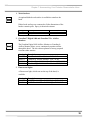
1
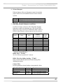
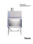
Protector® Demonstration Hoods
Models
3944300, 3944301
3945000, 3945001
3945020, 3945021
For more information, please contact us:
ExpotechUSA
10700 Rockley Road
Houston, Texas 77099
USA
281-496-0900 [voice]
281-496-0400 [fax]
E-mail: [email protected]
Website: www.ExpotechUSA.com
The information contained in this manual and the accompanying product is copyrighted and all rights are
reserved by Labconco Corporation. Labconco Corporation reserves the right to make periodic design
changes without obligation to notify any person or entity of such change.
Protector® Demonstration Hood
Warranty
Labconco provides a warranty on all parts and factory workmanship. The warranty includes areas of
defective material and workmanship, provided such defect results from normal and proper use of the
equipment.
The warranty for all Labconco products will expire one year from date of installation or two years from
date of shipment from Labconco, whichever is sooner, except the following:
•
•
•
•
Purifier® Delta® Series Biological Safety Cabinets and PuriCare® Procedure Stations carry a
three-year warranty from date of installation or four years from date of shipment from Labconco,
whichever is sooner.
FlaskScrubber®, SteamScubber and FlaskScrubber Vantage® Series Glassware Washers carry a
two-year warranty from date of installation or three-years from date of shipment from Labconco.
Carts carry a lifetime warranty.
Glass is not warranted from breakage due to accident or mishandling.
This limited warranty covers parts and labor, but not transportation and insurance charges. In the event of a
warranty claim, contact Labconco Corporation or the dealer who sold you the product. If the cause is
determined to be a manufacturing fault, the dealer or Labconco Corporation will repair or replace all
defective parts to restore the unit to operation. Under no circumstances shall Labconco Corporation be
liable for indirect, consequential, or special damages of any kind. This statement may be altered by a
specific published amendment. No individual has authorization to alter the provisions of this warranty
policy or its amendments. Lamps and filters are not covered by this warranty. Damage due to corrosion or
accidental breakage is not covered.
Limitation of Liability
The disposal and/or emission of substances used in connection with this equipment may be governed by
various federal, state, or local regulations. All users of this equipment are required to become familiar with
any regulations that apply in the user’s area concerning the dumping of waste materials in or upon water,
land, or air and to comply with such regulations. Labconco Corporation is held harmless with respect to
user’s compliance with such regulations.
.
Part #3943400 Rev ECO C399
TABLE OF CONTENTS
CHAPTER 1: INTRODUCTION
About This Manual
Typographical Conventions
1
2
3
CHAPTER 2: PREREQUISITES
Support Requirements
Location and Air Current Requirements
Exhaust and Blower Requirements
Electrical Requirements
Space Requirements
4
5
5
5
6
6
CHAPTER 3: GETTING STARTED
Unpacking the Hood
Installing the Hood on a Supporting Structure & Work Surface
Connecting to the Exhaust System
Connecting the Electrical Supply
Sealing to the Work Surface
Validating the Hood
7
8
8
10
16
16
16
CHAPTER 4: HIGH PERFORMANCE FEATURES AND
SAFETY PRECAUTIONS
High Performance Features
Safety Precautions
17
17
22
CHAPTER 5: USING YOUR PROTECTOR
DEMONSTRATION HOOD
24
CHAPTER 6: MAINTAINING YOUR PROTECTOR
DEMONSTRATION HOOD
Routine Maintenance Schedule
Calibration and Operation of Airflow Monitors
Guardian Jr. Airflow Monitor
Guardian Jr. Component Identification
Guardian Jr. Installation Procedure
26
26
27
27
28
29
Guardian Jr. Calibration Procedure
Guardian Jr. Alarm Activation
Guardian Jr. Alarm Test
Guardian Digital 1000 Airflow Monitor Operation
Guardian Digital 1000 Alarm Installation Procedure
Guardian Digital 1000 Alarm Calibration
31
33
33
33
33
35
CHAPTER 7: ACCESSORIZING YOUR PROTECTOR
DEMONSTRATION HOOD
Work Surfaces
Guardian Digital 1000 and Guardian Jr. Airflow Monitors
Fluorescent Light
Exhaust Transition Adapters
Remote Blowers
Exhaust Dampers
FilterMate Portable Exhausters and Filters
Storage Cabinets
Mobile Cart 8026000
Hose, Hose Clamps and Hose Kits
37
39
39
39
40
40
41
41
42
43
43
CHAPTER 8: TROUBLESHOOTING
44
APPENDIX A: REPLACEMENT PARTS
46
APPENDIX B: DIMENSIONS
50
APPENDIX C: SPECIFICATIONS
53
APPENDIX D: REFERENCES
56
DECLARATION OF CONFORMITY
59
CHAPTER 1
INTRODUCTION
Congratulations on your purchase of a Protector® Demonstration
Hood. Your high performance enclosure is designed to protect you
by providing superior containment while conserving energy at
OSHA approved “low flow” velocities as low as 60 feet per
minute. It is the result of Labconco’s more than 50 years
experience in manufacturing fume hoods.
The Protector Demonstration Hood has been engineered to provide
maximum containment. It will effectively contain toxic, noxious,
or other harmful materials when properly installed. The Protector
Demonstration Hood offers many unique features to enhance
safety, performance, and energy savings. To take full advantage of
them, please acquaint yourself with this manual and keep it handy
for future reference. If you are unfamiliar with how the Protector
Demonstration Hood operates, please review Chapter 4: High
Performance Features and Safety Precautions before you begin
working in the hood. Even if you are an experienced user, please
review Chapter 5: Using Your Demonstration Hood, which
describes the features so that you can use the hood efficiently.
1
Chapter 1: Introduction
About This Manual
This manual is designed to help you learn how to install, use, and
maintain your hood. Instructions for installing optional equipment
on your hood are also included.
Chapter 1: Introduction provides a brief overview of the hood,
explains the organization of the manual, and defines the
typographical conventions used in the manual.
Chapter 2: Prerequisites explains what you need to do to prepare
your site before you install the hood. Electrical and service
requirements are discussed.
Chapter 3: Getting Started contains the information you need to
properly unpack, inspect, install, and certify the hood.
Chapter 4: High Performance Features and Safety Precautions
explains how the Protector Demonstration Hood operates and the
appropriate precautions you should take when using the hood.
Chapter 5: Using Your Protector Demonstration Hood discusses
the basic operation of how to prepare, use and shut down your
hood.
Chapter 6: Maintaining Your Protector Demonstration Hood
explains how to perform routine maintenance on the hood.
Chapter 7: Accessorizing Your Protector Demonstration Hood
explains acceptable modifications to the hood or how to add
accessories.
Chapter 8: Troubleshooting contains a table of problems you may
encounter while using the hood including the probable causes of
the problems and suggested corrective actions.
2
Chapter 1: Introduction
Appendix A: Components contains labeled diagrams of all of the
components of the Protector Demonstration Hoods.
Appendix B: Dimensions contains comprehensive diagrams
showing all of the dimensions for the hoods.
Appendix C: Specifications contains the electrical requirements for
Protector Demonstration Hoods. Wiring diagrams are also
included.
Appendix D: References lists the various resources available that
address laboratory ventilation.
Typographical Conventions
Recognizing the following typographical conventions will help
you understand and use this manual:
•
•
•
•
•
•
Book, chapter, and section titles are shown in italic type (e.g.,
Chapter 3: Getting Started).
Steps required to perform a task are presented in a numbered
format.
Comments located in the margins provide suggestions,
reminders, and references.
Critical information is presented in boldface type in paragraphs
that are preceded by the exclamation icon. Failure to comply
with the information following an exclamation icon may result
in injury to the user or permanent damage to the enclosure.
Critical information is presented in boldface type in paragraphs
that are preceded by the wrench icon. A trained certifier or
contractor should only perform these operations. Failure to
comply with the information following a wrench icon may
result in injury to the user or permanent damage to your hood.
Important information is presented in capitalized type in
paragraphs that are preceded by the pointer icon. It is
imperative that the information contained in these paragraphs
be thoroughly read and understood by the user.
!
☞
3
CHAPTER 2
PREREQUISITES
Before you install the Protector Demonstration Hood, you need to
prepare your site for installation. Carefully examine the location
where you intend to install the hood. You must be certain that the
area is level and of solid construction. In addition, a dedicated
source of electrical power should be located near the installation
site to power the accessory FilterMate Portable Exhauster or other
apparatus.
Carefully read this chapter to learn the requirements for your
installation site:
•
•
•
•
•
The support requirements.
The location and air current requirements.
The exhaust and blower requirements.
The electrical power requirements.
The space requirements.
Refer to Appendix B: Dimensions for complete Protector
Demonstration Hood dimensions.
Refer to Appendix C: Specifications for complete electrical and
environmental conditions, specifications and requirements.
4
Chapter 2: Prerequisites
Support Requirements
At a minimum, the supporting structure usually consists of a base
cabinet, or a base stand and chemically-resistant work surface.
When setting up a chemical station, a mobile stand or cart is
allowable. Labconco manufactures a mobile cart with work
surface specifically designed to support the Protector
Demonstration Hood and FilterMate Portable Exhauster. The cart
is supplied with the Mobile Protector Demonstration Hood or can
be ordered separately as an accessory. See Chapter 7 for
accessories.
Location and Air Current
Requirements
The Protector Demonstration Hood has been designed to contain
hazards by negating typical cross drafts and movements within the
opening. As a precautionary measure it is recommended that the
enclosure be placed in such an area away from:
•
•
•
High traffic areas where walking might cause an air
disturbance.
Overhead or wall HVAC diffusers, fans, radiators or other lab
equipment producing air currents.
Next to doorways or windows that may be opened.
Exhaust and Blower
Requirements
The exhaust connection has been designed to accept a 2" x 10"
(5.1cm x 25.4cm) nominal exhaust collar. The Protector
Demonstration Hood has two possible exhaust connections with
either the top exhaust open and the bottom exhaust closed or vice
versa. The bottom exhaust connection is primarily used in
installations where the hose or ductwork will be concealed. The
bottom exhaust is used on the Mobile Protector Demonstration
Hood to conceal the exhaust and facilitate connection to the
FilterMate Portable Exhauster. Labconco offers accessory
Transition Adapters for the top or bottom exhaust connection to
either a 5" hose or 6" duct. (See Chapter 7 for ordering any of
these accessories). Only one exhaust connection is required. The
mobile Protector Demonstration Hood includes the lower 5" hose
exhaust transition, FilterMate Portable Exhauster, 5" hose, mobile
cart and work surface. Data for the exhaust volume and enclosure
5
Chapter 2: Prerequisites
static pressure loss are listed for each model at face velocities of
60, 80 and 100 fpm.
Demo
Hood
Width
3'
Demo
Hood
Height
22.75"
3'
32"
Model Description
Demonstration
Hood w/ 8" sash
opening
Demonstration
Hood w/ 10" sash
opening
Face
Velocity
(fpm)
60
80
100
60
80
100
Exhaust
Volume
(CFM)
110
145
185
140
185
230
Static
Pressure Loss
(in w.g..)
.04"
.06"
.10"
.06"
.10"
.15"
Proper blower selection can be determined from these exhaust
requirements and the total system static pressure loss. The
enclosure must be connected to either a dedicated blower, a house
exhaust system or a dedicated filtered exhauster, such as a
Labconco FilterMate Portable Exhauster.
Labconco offers three accessory remote blowers listed in Chapter
7.
Electrical Requirements
Standard duplex electrical receptacles should be nearby for
connecting the Demonstration Hood, FilterMate Portable
Exhauster, an airflow monitor, accessory Fluorescent Light or
other equipment. For your convenience both the accessory
FilterMate and accessory fluorescent light kit have auxiliary outlet
receptacles. It is required that the airflow monitor be connected
directly to the auxiliary switched outlet on the rear of the
FilterMate so the airflow monitor is ON when the blower is ON.
The FilterMate auxiliary switched outlet is rated for 8 amps.
For other blower exhaust systems, it is recommended that the
airflow monitor be switched by the same circuit as the exhaust
blower. If this is not possible, then the airflow monitor may be
connected to the switched auxiliary outlet on the accessory
fluorescent light kit. The fluorescent light kit auxiliary outlet can
be used for any accessory under 8 amps.
Space Requirements
The dimensions for the different models are shown in Appendix B:
Dimensions.
6
CHAPTER 3
GETTING STARTED
Now that the site for your Protector Demonstration Hood is
properly prepared, you are ready to unpack, inspect, install, and
validate your hood system. Read this chapter to learn how to:
• Unpack and move the hood.
• Set up the hood with the proper supporting structure and
work surface.
• Connect to an exhaust system.
• Connect the electrical supply.
• Seal the hood to the work surface.
• Arrange validation for the enclosure.
Depending upon which model you are installing, you may need
common plumbing and electrical installation tools in addition to
wrenches, ratchets, sockets, a nut driver set, a flat-blade
screwdriver, a Phillips screwdriver, and a carpenter level to
complete the instructions in the chapter.
!
The hoods weigh either 100 or 120 lbs. each (45
to 54 kg). The shipping container allows for
lifting with a mechanical lift truck or floor jack.
If you must lift the hood manually, follow safelifting guidelines. Do not lift by the front air
foil.
7
Chapter 3: Getting Started
Unpacking the Hood
The United States
Interstate Commerce
Commission rules
require that claims be
filed with the delivery
carrier within fifteen (15)
days of delivery.
Carefully remove the shrink-wrap or carton on the hood and
inspect it for damage that may have occurred in transit. If
damaged, notify the delivery carrier immediately and retain the
entire shipment intact for inspection by the carrier.
☞
DO NOT RETURN GOODS WITHOUT THE
PRIOR AUTHORIZATION OF LABCONCO.
UNAUTHORIZED RETURNS WILL NOT BE
ACCEPTED.
☞
IF ENCLOSURE WAS DAMAGED IN TRANSIT,
YOU MUST FILE A CLAIM DIRECTLY WITH
THE FREIGHT CARRIER. LABCONCO
CORPORATION AND ITS DEALERS ARE NOT
RESPONSIBLE FOR SHIPPING DAMAGES.
Do not discard the packing material until you have checked all of
the components and tested the unit.
We recommend that you do not remove the hood from its shipping
container until it is ready to be placed into its final location. Move
the unit by placing a flat, low dolly under the shipping skid, or by
using a floor jack.
!
Do not move the hood by tilting it onto a hand
truck.
Installing the Hood on a
Supporting Structure and Work
Surface
When installing the hood onto a chemically resistant work surface
or benchtop, ensure that the structure can safely support the
combined weight of the hood and any related equipment. The
work surface should be at least as wide as the hood to properly
support it. The front of the hood should be aligned within 1/8" of
the front of the work surface. Mounting holes are provided in
Labconco accessory work surfaces to secure the hood. The mobile
Demonstration Hood features a work surface attached to the cart.
8
Chapter 3: Getting Started
Work Surface Specifications
The work surface should be smooth, rigid, and durable, such as a
chemically resistant epoxy resin. The surface should be nonporous and resistant to the acids, solvents and chemicals used in
conjunction with the Protector Demonstration Hood. The work
surface should also contain a dished recessed area for containing
primary spills.
Work Surface and Hood Installation
1. Level the base cabinets and the work surface. Work
surface should be placed flush with the front of the base
cabinet as shown in Figure 3-1.
2. Position the work surface in its intended location and with
the front of the work surface (wide flange) towards you.
3. Secure the work surface to the base cabinet with a
structural adhesive or silicone sealant.
4. Insert the supplied mounting screws in the four holes.
Allow a minimum of 1/8" clearance under the head of the
screw for positioning the enclosure.
5. Place the hood on the work surface and slide the rear flange
and front air foil flanges under the mounting screw heads.
6. Tighten the four screws to complete the installation.
Side View of Typical
Installation
Figure 3-1
9
Chapter 3: Getting Started
Connecting to the Exhaust
System
!
WARNING: The weight of the exhaust
ductwork system must be supported
independently of the superstructure or damage
may occur.
The exhaust system should be installed by a
qualified HVAC contractor.
The exhaust connection on the Demonstration Hood
has been designed to accept a 2" x 10" (5.1cm x
25.4cm) nominal transition adapter. See Chapter 7
for ordering accessory transition adapters.
Labconco manufactures transition adapters for
either top or bottom exhaust and for both 5" dia.
hose or 6" dia. duct. Review Chapter 2 for remote
blower and FilterMate Portable Exhauster exhaust
prerequisites and review Chapter 7 for ordering
blower exhaust equipment. For your convenience
several exhaust options are shown in Figures 3-2, 33, 3-4, 3-5 and 3-6. Consult Labconco Customer
Service should you require help sizing your blower
for the exhaust volume and system static pressure
loss.
10
Chapter 3: Getting Started
6.03" ID
Exhaust
Transition
Adapter
Figure 3-2 Top Connection to Outside Exhaust
11
Chapter 3: Getting Started
To
Outside
Exhaust
Figure 3-3
Side View of Bottom Connection to
Outside
12
Chapter 3: Getting Started
Exhaust Transition
Adapter
Accessory
Fluorescent Light
Accessory
Airflow Monitor
5" ID Hose
included with
FilterMate
FilterMate
Portable
Exhauster
Figure 3-4
Top Connection to FilterMate Portable
Exhauster
13
Chapter 3: Getting Started
To Outside
Exhaust Via
Thimble
Connection
(6" nominal)
Figure 3-5
Bottom Connection to FilterMate
With Outside Thimble Exhaust Connection
14
Chapter 3: Getting Started
Accessory
Fluorescent Light
Accessory Airflow
Monitor
FilterMate
Portable
Exhauster
Back of Demonstration
Hood
Lower 5" ID
Hose Exhaust
Transition
Adapter
Back of FilterMate
Portable Exhauster
Figure 3-6
Connection to FilterMate on Mobile Cart
15
Chapter 3: Getting Started
Connecting the Electrical Supply
A standard duplex receptacle should be nearby for connecting the
FilterMate Portable Exhauster, airflow monitor and accessories.
Please review Chapter 2 for electrical prerequisites.
All wiring for the building duplex outlets
SHOULD be performed by a licensed electrician
and conform to all local codes.
Sealing to the Work Surface
When the hood has been set in place, ducted and wired, it may be
sealed at the work surface to prevent spilled materials from
collecting under the walls. A bead of silicone sealant is
recommended to seal the hood to the work surface.
Validating the Hood
The exhaust damper, exhaust blower or FilterMate gives you the
flexibility to change the airflow at the sash opening of your
enclosure. Determine the actual face velocity at the sash opening
by taking airflow velocity readings. These should be taken across
the sash opening of the enclosure in accordance with the Industrial
Ventilation Manual. (See Appendix D) The “average face
velocity” is achieved by taking readings in two rows across the
enclosure with the readings 6" from the ends and evenly spaced
every 12"; the first row is 3" down from the upper sash foil and the
second row is 3" up from the work surface. Labconco
recommends an average face velocity at the sash opening of 60 to
100 feet per minute for Protector Demonstration Hoods. Refer to
Chapter 2 for proper airflow volumes for your particular model.
Your Protector Demonstration Hood has been tested at the factory
per ASHRAE 110-1995. All enclosures achieve an “as
manufactured rating” of less than 0.05 part per million (ppm) at 4
liters per minute (lpm); AM <0.05 (Consult Labconco for
individual ratings). For “field use” ASHRAE testing contact
Labconco for a certified on-site contractor.
!
16
NOTE: Face velocity profiles and smoke testing
should be performed frequently per your
organization’s quality system to ensure safe
performance.
CHAPTER 4
HIGH PERFORMANCE
FEATURES AND SAFETY
PRECAUTIONS
High Performance Features:
The patented (U.S. Patent No. 6,461,233) Protector
Demonstration Hood is designed to meet the needs of a variety
of laboratory applications, and provide superior containment
while conserving energy at OSHA approved “low flow”
velocities as low as 60 feet per minute. The Protector
Demonstration Hood has been designed to effectively contain
toxic, noxious, or other harmful materials when properly
installed and operated. What makes the Protector
Demonstration Hood so unique is the revolutionary way it
directs air into and through the contaminated air chamber.
Labconco engineered the hood to minimize the effects of
turbulence. The containment enhancing and aerodynamic
designs of the upper sash foil, side air foils, lower air foil,
upper dilution air supply, and rear baffle all work in concert to
produce airflow patterns that significantly reduce both powder
and chemical concentrations through the work area. The
Protector Demonstration Hood incorporates unique 360°
visibility, which is useful in laboratory demonstrations and
visibility across classrooms.
17
Chapter 4: High Performance Features and Safety
14
3
12
6
13
9
2
8
5
4
1
10
7
16
Figure 4-1
18
Chapter 4: High Performance Features and Safety
1. Aerodynamic Clean-Sweep™ Air Foil has a unique low
profile shape that allows air to sweep the work surface for
maximum containment. The Clean-Sweep™ openings
create a constant protective barrier from contaminants. In
addition, should the operator inadvertently block the
airflow entering the air foil, air continues to pass under the
air foil and through the Clean-Sweep openings. See Figure
4-2.
Figure 4-2
2. Containment-Enhancing Upper Sash Foil includes a
perforated air passage directly atop the sash foil to bleed air
into the hood chamber and direct chemical and powder
concentrations away from the sash opening. The radiused
sash foil sweeps airflow into the hood with minimal
turbulence. See Figure 4-3.
Figure 4-3
19
Chapter 4: High Performance Features and Safety
3. Upper Dilution Air Supply provides bypass air from
above the work area. This feature constantly bathes the sash
interior with clean air and reduces powders and chemical
fumes along the sash plane, near the critical breathing zone.
Five to seven percent of the required air volume is
introduced through the upper dilution air supply to ensure
maximum containment. Additionally, the upper dilution air
supply reduces stagnant pockets of air in the upper interior.
See Figure 4-4.
Figure 4-4
4. Visible Clear Rear Baffle directs air streams to the baffle
in a single pass. The baffle and rear panel are
manufactured from framed glass panels to provide
maximum visibility on all sides. This smooth flow
minimizes the potential for air to roll forward preventing
contamination from moving toward the sash opening. The
concentrations of materials are largely removed on the first
pass through the contaminated chamber.
5. Side Entry Air Foils allow turbulence-free air to enter the
hood from the sides and allow clean air to sweep the
interior walls.
6. Ergonomic Slope provides maximum visibility, and
comfort reduces glare, thereby minimizing operator fatigue.
20
Chapter 4: High Performance Features and Safety
7. Internal Depth of 23" provides necessary space to support
equipment without extending outside the hood or resting on
the lower air foil.
8. Two Heights available as standard enclosures in 22.75" or
32". Taller height Demonstration Hoods are typically used
for pipet operations, titration or taller auxiliary equipment.
9. Unique Flush Sash with Spring-Loaded Latch has a
wiping seal to contain contaminants and features a springloaded latch for loading auxiliary equipment. The sash
pivots down for normal operation.
10. Electrical Pass through Iris allows electrical cords and
data cords to pass through the back of hood without leaving
a large hole for contaminants to escape. The hood ships
with solid plugs and the iris plugs are included with the
instruction manual for your convenience.
11. Shipped fully assembled to eliminate the need for costly
onsite assembly. Accessories such as the exhaust transition
connections, work surfaces, airflow monitors and
fluorescent light kits are easily installed.
12. Accessory Exhaust Connections. The Protector
Demonstration Hoods feature two exhaust locations: One
is located on the top of the rear plenum and the other is
located on the bottom of the rear plenum. The bottom
exhaust incorporates a tissue screen to prevent debris from
clogging the exhaust blower. Exhaust transition connectors
are available for either a 6" OD outside exhaust or a 5" ID
hose. All exhaust transition connectors are illustrated in
Chapters 2 and 3 and accessories listed in Chapter 7. The
lower 5" ID hose exhaust connection is used with the
mobile cart for connection to the FilterMate Portable
Exhauster which rests on the lower shelf.
13. Accessory Guardian™ Airflow Monitor or Guardian
Jr. Monitor continuously monitors airflow. An
audio/visual alarm alerts the user to low airflow conditions.
The Guardian™ 1000 Digital Airflow Monitor also
displays a face velocity value, provides an RS232 output, a
night setback mode and several auxiliary relay ports. See
Chapter 7 for ordering information.
14. Accessory Fluorescent Light Kits provide excellent
illumination with an auxiliary outlet plug for supplying
power to auxiliary equipment such as a balance or printer.
See Chapter 7 for ordering information.
21
Chapter 4: High Performance Features and Safety
15. Accessory Roof-Mounted Blower sized to provide
adequate airflow to Protector Demonstration Hoods when
used with an exhaust damper. See Chapters 2, 3 and 7.
16. Accessory FilterMate Portable Exhauster provides up to
280 cfm for HEPA or Carbon filtration or up to 220 cfm for
combination HEPA/Carbon filtration when connected to
the hood. See Chapters 2, 3 and 7.
17. Mobile Demonstration Hood includes FilterMate Portable
Exhauster, Demonstration Hood, work surface and mobile
cart to allow easy transport throughout the facility. See
Figure 3-6. Mobile cart can be ordered separately as shown
in Chapter 7.
Safety Precautions
!
!
!
Although the hood has been engineered to
maintain optimum operator safety, caution
should always be used while working. Prior
to using the hood, check to make sure that
the exhaust blower is operating and that air
is entering the hood at its specified face
velocity. The use of an airflow monitor is
recommended to alert the user if there is a
problem with airflow.
Use good housekeeping in the hood at all
times. Clean up spills immediately.
Periodically clean enclosure interior.
Do not overload the work surface with
apparatus or work material. The safe
operation of the hood is based upon having
proper airflow through the structure. Do not
place large, bulky objects such as block
heaters, directly on the work surface.
Instead, elevate the object 3/4" on blocks to
allow a flow of air under the object and into
the rear baffle exhaust slots. Ensure blocks
are level and secured in place.
Blocking large portions of the rear baffle will
change the airflow pattern in the hood
causing turbulence. (Do not store containers
22
Chapter 4: High Performance Features and Safety
or supplies against the rear baffle, as this will
affect airflow).
Always work with your hands as far back in
the hood as possible. It is best to keep all
powders, chemicals and apparatus inside the
lower air foil of the hood.
!
Do not work with chemicals in this hood
without the exhaust system running.
Perchloric acid use in this hood is prohibited.
!
High-level radioisotope materials are
prohibited in this hood.
Avoid cross drafts and limit traffic in front of
the hood. Air disturbances created may
draw contaminants out of the hood.
The hood should be tested by a qualified
certification technician before it is initially
used. The hood should be validated
whenever it is relocated, serviced or at least
annually thereafter.
The use of safety goggles, protective clothing,
gloves and any other personal protective
equipment recommended by your safety
officer should be used.
The sash should remain in the down position
while using the hood.
Proper operation of the hood depends largely
upon its location and the operator’s work
habits. Consult the references in Appendix D.
23
CHAPTER 5
USING YOUR
PROTECTOR
DEMONSTRATION HOOD
Planning
• Thoroughly understand procedures and equipment required
before beginning work.
• Arrange for minimal disruptions, such as room traffic or
entry into the room while the hood is in use.
Start-up
• Turn on exhaust system and accessory light if so equipped.
• Only raise the sash for loading.
• Check the baffle air slots for obstructions.
• Allow the enclosure to operate unobstructed for 1 minute.
• Wear a long sleeved lab coat and rubber gloves. Use
protective eyewear. Wear a protective mask if appropriate.
Consult your Safety Officer for additional personal
protective equipment recommendations.
Loading Materials and Equipment
• Only load the materials required for the procedure. Do not
overload the hood.
• Do not obstruct the air foil, or rear baffle slots.
• Large objects should not be placed close together and
should be elevated above the work surface to permit
airflow to sweep under the equipment.
24
Chapter 5: Using Your Protector Demonstration Hood
Work Techniques
• Keep all materials inside the lower air foil, and perform all
contaminated operations as far to the rear of the work area
as possible.
• Segregate all clean and contaminated materials in the work
area.
• Avoid using techniques or procedures that disrupt the
airflow patterns of the hood.
Final Purging
• Upon completion of work, the hood should be allowed to
operate for two to three minutes undisturbed, to purge
airborne contaminants from the work area before shutting
down the blower.
Unloading Materials and Equipment
• Objects in contact with contaminated material should be
surface decontaminated before removal from the hood.
• All open trays, weigh vessels or chemical containers should
be covered before being removed from the hood.
Shutdown
• Turn off the exhaust system and accessory light if provided.
25
CHAPTER 6
MAINTAINING YOUR
PROTECTOR
DEMONSTRATION HOOD
Now that you have an understanding of how to work in the hood,
we will review the suggested maintenance schedule and the
common service operations necessary to maintain your hood for
peak performance.
!
Only trained and experienced certification
technicians should perform some of the service
operations after the hood has been properly
decontaminated. DO NOT attempt to perform
these operations if you are not properly trained.
The wrench icon precedes the service operations
that require qualified technicians.
Routine Maintenance Schedule
Weekly
• Clean the hood interior appropriate for the application.
• Operate the exhaust system, noting the airflow velocity
through the enclosure using a source of visible smoke.
Airflow alarms are recommended for constant monitoring.
26
Chapter 6: Maintaining Your Protector Demonstration Hood
Monthly (or more often as required)
• Determine the actual face velocity through the sash opening
of the hood where the average reading should be at the
specified velocity. (Use calibrated thermal anemometer or
other approved apparatus). Airflow alarms are
recommended for constant monitoring.
• Using a cloth and glass cleaner, clean the exterior surfaces
of the hood, particularly the front of the hood, to remove
any accumulated dust.
• The hood rear baffle should be checked for any blockage to
ensure that the enclosure is maintaining proper airflow.
• All weekly activities.
Annually
• Have the hood validated by a qualified certification
technician. See Validating the Hood in Chapter 3.
• All monthly activities.
Calibration and Operation of
Airflow Monitors
Guardian Jr. Airflow Monitor
The Guardian Jr. Airflow Monitor is designed to continuously
monitor airflow through hoods. This permanently installed device
provides both visual and audible alarms to alert the user of
abnormal airflow conditions. A green light on the front of the
monitor indicates normal flow conditions. When flow conditions
lower than the set point are encountered, a red light is activated
along with an audible alarm. A test button is provided at the front
of the monitor to allow the user to check the operation of the
alarm. To temporarily mute the audible alarm, press and release
the test/reset button.
27
Chapter 6: Maintaining Your Protector Demonstration Hood
Guardian Jr. Component
Identification
1.
Air Inlet
A portion of the air coming into the hood passes through the
air inlet and across the flow sensors.
2.
Normal Flow
Indicator
This green light indicates normal flow conditions.
3.
Alarm Indicator
This red light is activated approximately 6 seconds after the
low flow set point is reached.
4.
Test/Reset Button
If no alarm is present, this button will cause the red lamp to
light and the audible alarm to sound. If an alarm is present,
the button will silence the audible alarm.
5.
Adjustment for
Alarm Set Point
This potentiometer is used to set the low flow indicators for
the alarm. It is adjusted with a small screwdriver.
1
3
2
4
5
Figure 6-1
Guardian Jr. Components
28
Chapter 6: Maintaining Your Protector Demonstration Hood
Guardian Jr. Installation
Procedure
1. The hood comes prepared to except the Guardian™ Jr. airflow
monitor system.
2. First remove the small 0.50" dia. gray hole plug and two #8-32
x 0.50" self-tapping Phillips screws from the hood. Keep the
screws for step 5. See Figure 6-2.
See Figure 6-3 for steps 3 through 9.
3. Open the top monitor cover by removing the two #8-32 x .38"
lg. Phillips screws to access the tube stem and clear plastic
tubing.
4. Temporarily remove the tube stem, Item 1 in Figure 6-3, and
clear plastic tubing, Item 2.
5. Without the tube stem and clear plastic tubing attached, mount
the Guardian Jr. alarm module to the hood with the two #8-32
x 0.50” screws removed in step 2.
6. Install the tube stem by tapping the non-serrated end of the
tube stem into the 0.50" hole on the enclosure. Silicone sealant
may be applied between the tube stem and the hood.
7. Route the clear plastic tubing without kinks between the rubber
elbow tubing connector on the back of the Guardian Jr. alarm
module and the tube stem. This completes the airway passage
between the alarm module and the hood.
8. Locate the 9VDC power supply transformer, which should
already be connected to the back of the alarm module through
the strain relief bushing. If disconnected, then reconnect to the
airflow monitor. Plug the 9VDC power supply into a 115V
duplex receptacle, the back of the accessory FilterMate
Portable Exhauster or the back of the accessory fluorescent
light. For 230V, plug the power supply into an adapter or add
an extension cable for connection to the FilterMate. It is
recommended that the airflow monitor be connected
directly to the FilterMate switched auxiliary outlet so the
airflow monitor is powered at the same time.
9. Finish the installation by re-attaching the top monitor cover
with two #8-32 x .38" lg. Phillips screws from step 3.
29
Chapter 6: Maintaining Your Protector Demonstration Hood
#8-32 x .50"
Self-Tapping
Phillips Screws
Small 0.50"
Dia. Hole
Plug
Large 1.19" Dia.
Hole Plug
Figure 6-2
Hole Plug Location & Mounting Screws
Cover
Airflow
Monitor
Rubber
Elbow
Clear
Plastic
Tubing
Item #2
Tube Stem
Item #1
Figure 6-3
Guardian Jr. Details
30
Chapter 6: Maintaining Your Protector Demonstration Hood
Guardian Jr. Calibration
Procedure
Each Guardian Jr., alarm module and hood is unique and needs to
be individually calibrated in the field. The procedure for the
adjustment is as follows:
1. Double check the installation instructions to make sure that
monitor and power supply are properly installed.
2. Allow 10 minutes for the monitor to warm up once power
has been connected.
3. Determine the low flow set point for your monitor. This is
the value where the monitor will first indicate a low flow
condition. The red light will be on for this value. Refer to
your industrial hygiene officer for the proper low flow set
point or consult the table to follow.
4. Adjust your hood airflow to the low flow set point as
previously determined. The exhaust flow can be lowered
by adjusting the speed control on the FilterMate or by using
an adjustable damper on the exhaust blower. Typical alarm
conditions are set at face velocities of 10 to 20 feet per
minute below the normal operating conditions due to
supply air and exhaust air fluctuations, as well as room air
cross drafts.
5. Using a properly calibrated thermoanemometer, determine
the velocity through the face of the hood by taking a
detailed velocity traverse. Divide the face area into equal
increments. One reading per square foot of face area is
normally recommended for an accurate traverse. Compute
the average velocity for this area.
6. If the red light alarm is on, slowly turn the adjustment
screw counterclockwise until the green light is activated. If
the green light is on, slowly turn the adjustment screw
clockwise until the red light comes on. Slowly turn the
adjustment screw back until the red light is activated. It is
important that these adjustments be done in small
increments, at intervals about 10 seconds apart to allow for
delayed reaction of the alarm itself. The alarm low flow set
point should now be set and the red light activated.
7. Readjust the hood airflow to its normal operating levels.
The green light should now be activated.
8. Calibration is now complete.
31
Chapter 6: Maintaining Your Protector Demonstration Hood
Enclosure Operating In
Flow Speed
100 fpm
80 fpm
60 fpm
Alarm Condition Set
Point Speed
80 - 90 fpm
60 - 70 fpm
40 - 50 fpm
Accessory Light
Airflow Monitor
Installed
Enclosure
Figure 6-4
Guardian Jr., Installed
32
Chapter 6: Maintaining Your Protector Demonstration Hood
Guardian Jr. Alarm Activation
The audio and visual alarm will activate approximately six seconds
after an alarm condition is detected. To temporarily mute the
audible alarm, press and release the test/reset button.
NOTE: After an alarm condition has been detected, the red light
will stay on. The audible alarm will remain muted until airflow
returns to normal levels.
Guardian Jr. Alarm Test
When no alarm is present the alarm can be tested by pressing the
test/reset button. While the button is pressed, the alarm light and
audible alarm will be activated.
Guardian Digital 1000 Airflow
Monitor Operation
The Guardian Digital Airflow Monitor consists of the airflow
sensor, the alarm and the 15 VDC power supply. For 115V
operation the alarm unit is powered by plugging the power supply
into the factory-prepared digital airflow monitor socket. For 230V
operation, the alarm is powered by plugging the power supply into
a building outlet. The alarm has “Enter”, “+”, and “-” buttons to
program the monitor. There is also a green LED “SAFE”, yellow
LED “CAUTION”, and red LED “LOW” with audible alarm for
airflow conditions. The audible alarm can be permanently muted
if desired. The Guardian Digital 1000 Airflow Monitor displays a
face velocity value, provides an RS232 communications port to a
PC or building computer system, can be configured for external
input connections such as night setback or external alarm and
provides up to three output relays that can be configured. For
complete detailed information, please refer to the separate
Guardian 1000 Alarm User’s Manual provided with the enclosure.
Guardian Digital 1000 Installation
Procedure
1. The hood comes prepared to except the Guardian 1000 Digital
Airflow Monitor.
2. First remove the large 1.19" dia. gray hole plug and two #8-32
x 0.50" self-tapping Phillips screws from the hood. Keep
33
Chapter 6: Maintaining Your Protector Demonstration Hood
the screws for step 3. See Figure 6-2. See Figure 6-5 only to
reference internal assembly of the airflow monitor.
3. Secure the Guardian Digital Monitor to the enclosure with the
two #8-32 x 0.50" screws removed from step 2.
4. The airway passage between the alarm module and the hood is
now complete.
5. Locate the 15VDC power supply transformer. One end should
already be connected to the two-pin connector labeled 15 VDC
on the back of the alarm module and through the strain relief
bushing. If disconnected, then reconnect to power the airflow
monitor. Plug the 115V power supply into a 115V duplex
receptacle, the back of the accessory FilterMate Portable
Exhauster or the back of the accessory fluorescent light. For
230V, plug an adapter or add an extension cable for connection
to the FilterMate. It is recommended that the airflow
monitor be connected directly to the FilterMate switched
auxiliary outlet so the airflow monitor is powered at the
same time.
6. Installation is now complete.
Display Digital
1000 Monitor
Airflow
Sensor
Figure 6-5
Guardian Digital 1000 Monitor Details
34
Chapter 6: Maintaining Your Protector Demonstration Hood
Guardian Digital 1000 Calibration
1. Calibrate the airflow monitor according to the monitor
User’s Manual that comes with the kit and follow the
instructions below. To successfully calibrate, it will be
necessary to change the face velocity by adjusting the
airflow exhaust volume. The exhaust volume can be
adjusted with the speed control on the FilterMate or by
using an adjustable damper on the exhaust blower. Typical
calibration conditions are set at face velocity air sample
differences of at least 20 feet per minute. The airflow
monitor is factory set to be calibrated with a difference of
at least 50 fpm and can be changed by changing the
“lower/higher air sample difference.” The following
suggested in flow face velocity speeds are recommended to
successfully calibrate. Typical low air alarms are set 10-20
fpm below operational speeds. Follow Step 2 below and
review the Guardian 1000 Alarm User’s Manual that comes
with the airflow monitor.
Low Air
Alarm
Set
Point
40 - 50
fpm
60 - 70
fpm
80 – 90
fpm
Enclosure
Operating
Inflow
Speed
60 fpm
Low
Calibration
Set Point
High
Calibration
Set Point
40 - 60 fpm
80 fpm
50 - 90 fpm
100 fpm
50 – 110 fpm
100 – 120
fpm
100 – 150
fpm
100 – 170
fpm
2. Go to SETUP menu and then CAL CONFIG MENU and
change the “lower/higher air sample difference” to 20 fpm.
This will allow you to successfully calibrate with values of
a minimum of 20 fpm difference.
3. While in CAL CONFIG MENU, change the “sensor
difference” from 10% to 3%.
4. While in CAL CONFIG MENU, adjust the red low air
alarm to the desired setting such as 60 fpm. Then adjust
the yellow “CAUTION or WARNING” to 63 fpm, if
desired. Then adjust the “CAUTION or WARNING” air
reset to 3 fpm. This sets the alarm condition.
5. To complete the CAL CONFIGURATION, be sure to enter
“DONE”.
35
Chapter 6: Maintaining Your Protector Demonstration Hood
6. To start the calibration mode, use the Guardian Digital
1000 Monitor User’s Manual and enter “CALIBRATION”
mode on the display from the SETUP menu.
7. Follow the instructions on the display and alter the low
exhaust volume with the speed control on the FilterMate or
exhaust damper. Measure the average face velocity and
enter the low value on the display. Be careful not to block
the opening. The low exhaust volume calibration will take
about 5 seconds.
8. Now alter the high exhaust volume with the speed control
on the FilterMate or exhaust damper. Measure the average
face velocity and enter the high value on the display. The
high value must be at least 20 fpm greater than the low
value. The high exhaust volume calibration will take about
5 seconds.
9. Enter “DONE” after successfully completing the low and
high calibration set points.
10. Once calibration is completed, go to “RUN” and press
“ENTER”. The value should read close to the high
calibration set point.
11. To lower the face velocity to the operating point, simply
alter the exhaust volume with the speed control on the
FilterMate or exhaust damper. Then recheck the face
velocity with an anemometer to confirm the display on the
digital airflow monitor.
Accessory Light
Demonstration
Hood
Airflow Monitor
Installed
Figure 6-6
Guardian Digital 1000 Monitor Installed on Demonstration Hood
36
CHAPTER 7
ACCESSORIZING YOUR
PROTECTOR
DEMONSTRATION HOOD
There are several ways to accessorize the hood for your individual
requirements. These include the addition of accessory work
surfaces, airflow monitors, fluorescent lights, exhaust transition
adapters, hoses, remote blowers, exhaust dampers, FilterMate
Portable Exhausters, filters, storage cabinets and mobile carts.
37
Chapter 7: Accessorizing Your Protector Demonstration Hood
Optional Equipment for the Demonstration Hood
4
3
2
5" ID
Hose
1
7
8
5 – Remote Blower – Not Shown
6 – Exhaust Damper – Not Shown
9 – Mobile Cart – Not Shown
Figure 7-1
38
Chapter 7: Accessorizing Your Protector Demonstration Hood
1. Work Surfaces
An optional dished work surface is available to attach to the
hood.
Dished work surfaces are contoured to fit the dimensions of the
hood to contain spills. Epoxy is chemical-resistant.
Catalog #
3908402
3908405
Description
Black, 4-foot wide
Gray, 4-foot wide
Dimensions (W x D x H)
48" x 26.66" x 1"
48" x 26.66" x 1"
2. Guardian™ Digital 1000 and Guardian™ Jr. Airflow
Monitors
The Guardian Digital 1000 Airflow Monitor or Guardian Jr.
Airflow Monitor allows you to continuously monitor airflow
through the hood. The rear exhaust plenum is factory prepared
to mount either monitor.
Catalog #
3908700
3908701
3908800
3908801
Description
Guardian Jr. Airflow Monitor, 115V, 60 Hz
Guardian Jr. Airflow Monitor, 230V, 50 Hz
Guardian Digital 1000 Airflow Monitor 115V, 60 Hz
Guardian Digital 1000 Airflow Monitor 230V, 50 Hz
3. Fluorescent Lights
A fluorescent light, which rests on the top of the hood, is
available.
Catalog #
3909200
3909201
Description
18.25" W x 10.12"D x 3.00" H Light, 115V, 60 Hz
18.25" W x 10.12"D x 3.00" H Light, 230V, 50 Hz
39
Chapter 7: Accessorizing Your Protector Demonstration Hood
4. Exhaust Transition Adapters
Adapter connects to the hood from either the top or the bottom
of the rear plenum so the duct can be routed either up or down,
respectively. The transition is available for either 5.00" ID
hose or 6" OD duct. The 5.00" ID hose lower connection is
included with the FilterMate supplied with the mobile cart.
Catalog #
3912400
3912401
3912402
3912403
Description
Upper connection, 5" Hose
Upper connection, 6" Duct
Lower connection, 5" Hose
Lower connection, 6" Duct
Material
Epoxy-Coated Steel
Epoxy-Coated Steel
Epoxy-Coated Steel
Epoxy-Coated Steel
5. Remote Blowers
Has a 1/4 hp direct drive motor and corrosion-resistant
phenolic coated-steel housing and wheel with blower inlet of
6.00" ID. Outlet dimensions are 4.25" x 7.38" OD.
0.0"
595
Catalog #
Description
4863500
4863501
Remote Blower, 115 V, 60 Hz. 4.4 amps
Remote Blower, 115/230 V, 50 Hz, 5.6/2.8 amps
Explosion-Proof Remote Blower, 115 V, 60 Hz,
4.4 amps
7053501
40
CFM @ Static Pressure-Inches of H2O
0.125" 0.25"
0.50"
0.75"
0.87"
560
515
420
300
167
S.P.
CFM
Shipping Wt.
(lbs./kg.)
35/16
35/16
40/18
Chapter 7: Accessorizing Your Protector Demonstration Hood
6. Exhaust Dampers
Exhaust dampers allow an adjustment required to maintain
proper airflow for roof-mounted blowers or house exhaust
systems.
Catalog #
3924000
4724200
Description
6" Epoxy-Coated Steel In-Line Adjustable Damper
6" PVC In-Line Adjustable Damper
7. FilterMate Portable Exhausters and Filters
For filtered exhaust, Labconco offers FilterMate Portable
Exhausters capable of exhausting up to 280 cfm of HEPA
filtered air or up to 220 cfm of combination Dual Carbon or
HEPA/Carbon filtered air when connected to the enclosure.
Catalog #
3970000
3970001
3970002
3970003
3970004
3970020
3970021
3970022
3970023
3970024
Voltage
Filter
Exhaust
Connection
115 Volt/60 Hz
115 Volt/60 Hz
115 Volt/60 Hz
115 Volt/60 Hz
115 Volt/60 Hz
230 Volt/50 Hz
230 Volt/50 Hz
230 Volt/50 Hz
230 Volt/50 Hz
230 Volt/50 Hz
HEPA
Carbon
HEPA
HEPA/Carbon
Carbon/Carbon
HEPA
Carbon
HEPA
HEPA/Carbon
Carbon/Carbon
None
None
Thimble to outside
None
None
None
None
Thimble to outside
None
None
Exhaust
Airflow
(cfm)
280
280
280
220
220*
280
280
280
220
220*
*Indicates model supplied with mobile cart with lower 5"
exhaust transition included.
HEPA Filter - 3707900
99.99% efficient on particles 0.3 micron.
HEPA Filter Bag-In/Bag-Out Bag - 3776002
Helps contain hazardous particulate matter during filter
changing operations.
Carbon Filter
Provides granular activated carbon or impregnated carbon.
Filter Classification
Organic
Formaldehyde
Ammonia
Catalog #
3923400
3923401
3923402
x Pounds
12.0 lbs activated carbon
14.0 lbs impregnated carbon
16.0 lbs impregnated carbon
41
Chapter 7: Accessorizing Your Protector Demonstration Hood
8. Storage Cabinets
Size/Description
48"
36"
30"
24"
18"
12"
48" w/Self Closing Doors
36" w/Self Closing Doors
30" w/Self Closing Doors
24" w/Self Closing Doors
24" ADA
24" ADA w/Self Closing
Doors
18" ADA
12" ADA
Size/Description
48"
36"
30"
24"
18"
12"
48" w/Self Closing Doors
36" w/Self Closing Doors
30" w/Self Closing Doors
24" w/Self Closing Doors
24" ADA
24" ADA w/Self Closing
Doors
18" ADA
12" ADA
42
Dual Doors
9902000
9902100
9902200
9903000
9903100
9903200
-
SOLVENT
Right Hinge
9902300
9903300
9906000
9906200
-
STANDARD BASE
Dual Doors
Right Hinge
9900000
9900100
9900200
9900300
9900400
9900500
9904000
-
9904100
9904200
Left Hinge
9902400
9903400
9906100
9906300
Dual Doors
9901000
9901100
9901200
-
ACID
Right Hinge
9901300
9901400
9905000
-
Left Hinge
9901500
9901600
9905200
-
-
-
9905100
-
9905300
-
Left Hinge
9900600
9900700
9900800
9904300
9904400
9904500
VACUUM PUMP
Dual Doors Right Hinge Left Hinge
9907000
9907100
-
-
-
Chapter 7: Accessorizing Your Protector Demonstration Hood
9. Mobile Cart 8026000
Provides a mobile cart and dished solid epoxy work surface for
supporting the Protector Demonstration Hood.
10. Hoses, Hose Clamps, and Hose Kits
Provides alternatives for ducting.
Catalog #
4868600
1921000
3927500
3927600
1921500
Description
8 Feet of 5" ID gray flexible polypropylene hose (included with
FilterMate). General purpose chemical-resistant hose suitable in
pharmaceutical applications.
5" T-Bolt Hose Clamp (two included with FilterMate)
8 Feet of 5" ID clear smooth bore static dissipation hose with two hose
clamps. Suitable in clean rooms or pharmaceutical applications.
8 Feet of 6" ID black thermoplastic hose with two 6.09" ID cuffs.
Include two 6" hose clamps. Suitable for connection to house exhaust
in pharmaceutical applications.
6" T-Bolt Hose Clamp
43
CHAPTER 8
TROUBLESHOOTING
Refer to the following table if your Protector Demonstration Hood
fails to operate properly. If the suggested corrective actions do not
solve your problem, contact Labconco for additional assistance.
44
PROBLEM
CAUSE
CORRECTIVE ACTION
Contaminants
outside of enclosure
Improper user
techniques for the
enclosure.
See “Certifying the Hood” Chapter 3
and “Safety Precautions” Chapter 4
sections in the manual. (Ref. Appendix
D)
Restriction of the
baffle air slots or
blockage of the
exhaust outlet.
Remove obstruction to ensure that all
air slots and the exhaust outlet are
unobstructed.
External factors are
disrupting the hood
airflow patterns or
acting as a source of
contamination.
See “Location Requirements” Chapter
2, “Certifying the Hood” Chapter 3,
and “Safety Precautions” Chapter 4
sections of this manual. (Ref. Appendix
D)
Hood has improper
face velocity.
Have hood certified and check exhaust
system. Check FilterMate filters for
loading. Adjust FilterMate speed
control. Hood should have average
face velocity of 60-100 fpm.
Chapter 8: Troubleshooting
PROBLEM
Airflow monitor
malfunction.
CAUSE
No power.
No lights.
No display.
No audible alarm.
Wrong alarm set
point.
Constant audible
alarm.
Continuous alarm.
Monitor alarms; air
way to airflow
monitor sensor is
blocked by insects,
dust or debris.
Audible disable
will not stay ON
CORRECTIVE ACTION
Power supply is not plugged into
proper voltage; plug in power
supply. Verify that airflow monitor
interface cables are connected.
Check fuses on FilterMate or
accessory light.
Alarm has been temporarily silenced
using “test/reset” or “enter” buttons.
Airflow monitor was not properly
adjusted. Repeat calibration steps
outlined in the airflow monitor
manual.
Check airflow and calibration of
airflow monitor.
Check the face velocity of the
enclosure as the airflow may have
changed. If face velocity is correct,
calibrate the airflow monitor as
outlined in the User’s Manual.
Lightly clean the airway with clean
air. Be careful not to touch sensitive
electrical components.
An alarm condition must be
continuously present before the
audible alarm can be silenced. If
flow conditions fluctuate near the
alarm set point, the airflow monitor
will automatically reset itself.
Action should be taken to bring the
hood airflow into proper operating
parameters or adjust the alarm set
point lower.
45
APPENDIX A
REPLACEMENT PARTS
The following illustrations indicate the replacement parts.
46
Appendix A: Replacement Parts
Item
1A
1B
2
3A
3B
4
5
6A
6B
7A
7B
7C
7D
7E
7F
8A
8B
9A
9B
9C
9D
9E
10
11
12
13A
13B
13C
13D
14A
14B
15A
15B
15C
16A
16B
16C
17
18
19
Qty.
1
1
1
1
1
1
2.3 Ft.
1
1
1
1
1
2
1
1
1
1
1
1
2
2
2
1
1
1
1
1
1
1
1
1
2
2
2
2
2
4
1
1
1
Part Number
3906500
3926500
3906801
3906101
3926101
3907601
6913700
3907500
3907501
1927403
3906700
6916500
1893206
6916501
3925300
3905201
3925201
3907400
3907401
1932401
1912108
1909217
3905601
3905301
3913100
3912400
3912401
3912402
3912403
1934601
1936800
7868402
1912108
1889316
3915400
3915401
1889912
1595619
1595621
3941900
Description
Glass, Side Short
Glass, Side Tall
Glass, Top 3'
Glass, Sash 3' Short
Glass, Sash 3' Tall
Foil, Sash 3'
Wiper, Sash
Stop, Right Sash
Stop, Left Sash
Spring, Compression Sash Latch
Latch Bracket
Latch Sash
Screw, #8-32 x .38 Phil, SS, Type F
Latch Sash Tall
Latch Bracket Tall
Sash Assembly 3', Short
Sash Assembly 3' Tall
Bracket, Air Foil Right
Bracket, Air Foil Left
Washer, Shoulder Plastic
Washer, .194 ID x .38 OD x .03 thick plastic
Cap Nut #10-24 SS
Air Foil 3'
Header 3'
Cover Plate, Exhaust (Top or Bottom)
Upper Exhaust Transition 5" Hose
Upper Exhaust Transition 6" Duct
Lower Exhaust Transition 5" Hose
Lower Exhaust Transition 6" Duct
Bushing, Heyco with Flex Shutter 1.50 dia.
Bushing, Heyco Closed 1.50 dia.
Spacer Bushing
Washer, .194 ID x .38 OD x .03 T. Plastic
Screw, #10-24 x 1.00 PH. (SS)
Side Air Foil, Short
Side Air Foil, Tall
Screw, 6-32 x .75 PH. Type F, Oval Head
Hole Plug, .500 dia. Gray
Hole Plug, 1.187 dia. Gray
Label, Protector Demonstration Hood
47
Appendix A: Replacement Parts
Item
20A
20B
20C
20D
21
22
Qty.
1
1
2
2
1
4
Part Number
3942500
3941700
1914200
1923900
3943000
8009501
Description
Baffle Assy, Short
Baffle Assy, Tall
Captive Screw, Baffle
Receptacle, Clip-on
Shelf, Demo Cart
Caster 4" w/ Brake Demo Cart
2
12
19
17,18
Not Shown
11
5
7
15
3
1
6
8
4
16
10
22
9
21
Figure A-1A
48
Appendix A: Replacement Parts
20
14
13
Figure A-1B
49
APPENDIX B
DIMENSIONS
See the following dimensions.
50
Appendix B: Dimensions
Figure B-1
Protector Demonstration Hood Dimensions
51
Appendix B: Dimensions
Figure B-2
Protector Mobile Demonstration Hood Dimensions
52
APPENDIX C
SPECIFICATIONS
Electrical Specifications
115V, 60 Hz Mobile Demonstration Hood, 10 Amps Max.
230V, 50/60 Hz Mobile Demonstration Hood, 5 Amps Max.
Environmental Conditions
•
•
•
•
•
•
•
Indoor use only.
Maximum altitude: 6562 feet (2000 meters).
Ambient temperature range: 41° to 104°F (5° to 40°C).
Maximum relative humidity: 80% for temperatures up to
88°F (31°C), decreasing linearly to 50% relative humidity
at 104°F (40°C).
Main supply voltage fluctuations not to exceed ±10% of the
nominal voltage.
Transient over-voltages according to Installation Categories
II (Over-voltage Categories per IEC 1010). Temporary
voltage spikes on the AC input line that may be as high as
1500V for 115V models and 2500V for 230V models are
allowed.
Used in an environment of Pollution degrees 2 (i.e., where
normally only non-conductive atmospheres are present).
Occasionally, however, a temporary conductivity caused by
condensation must be expected, in accordance with IEC
664.
53
Appendix C: Specifications
54
Appendix C: Specifications
55
APPENDIX D
REFERENCES
Many excellent reference texts and booklets are currently
available. The following is a brief listing:
Laboratory Ventilation Standards
Federal Register 29 CFR Part 1910
Non-mandatory recommendations from “Prudent Practices”.
• Fume hoods should have a continuous monitoring device
• Face velocities should be between 60-100 linear feet per minute
(lfpm)
• Average 2.5 linear feet of hood space per person
Occupational Health and Safety
U.S. Department of Labor
200 Constitution Avenue N.W.
Washington, DC 20210
(202) 523-1452
www.osha.gov
Industrial Ventilation-ACGIH
• Fume hood face velocities between 60-100 lfpm
• Maximum of 125 lfpm for radioisotope hoods
• Duct velocities of 1000-2000 fpm for vapors, gasses and smoke
• Stack discharge height 1.3-2.0 x building height
• Well designed fume hood containment loss, <0.10 ppm
Industrial Ventilation, A Manual of Recommended Practice.
24th Edition, 2001
American Conference of Governmental Industrial Hygienists
1330 Kemper Meadow drive
Cincinnati, OH 45240-1634
(513) 742-2020
www.acgih.org
56
Appendix D: References
ASHRAE 110-1995 Method of Testing Performance of Fume Hoods
Evaluates fume hood’s containment characteristics
• Three part test: Smoke generation, Face velocity profile, Tracer gas
release @ 4 liters per minute
• Rated As Manufactured (AM), As Installed (AI) and As Used (AU)
American Society of Heating, Refrigerating, and Air Conditioning
Engineers
1791 Tullie Circle N.E.
Atlanta, GA 30329
(404) 636-8400
www.ashrae.org
ANSI Z9.5-1993 Laboratory Standard
Covers entire laboratory ventilation system.
• Vertical stack discharge @ 2000-3000 fpm
• New and remodeled hoods shall have a monitoring device
• Ductless hoods should only be used with non-hazardous materials
• Fume hood face velocities between 80 – 120 fpm
American Industrial Hygiene Association
2700 Prosperity Avenue, Suite 250
Fairfax, VA 22031
(703) 849-8888
www.aiha.org
SEFA 1-2002
• Fume hood face velocities based on toxicity levels of chemicals
Class A – 125 to 150 fpm
Class B – 80 to100 fpm
Class C – 75-to 80 fpm
• Test method – face velocity profile and smoke generation
Scientific Equipment & Furniture Association
1028 Duchess Drive
McLean, VA 22102
(703) 538-6007
www.sefalabs.com
NFPA 45 – 2002 Fire Protection for Laboratories Using Chemicals
• Laboratory hoods should not be relied on for explosion protection
• Exhaust air from fume hoods should not be recirculated
• Services should be external to the hood
• Canopy hoods only for non-hazardous applications
• Materials of construction should have flame spread of 25 or less
• 80 to 120 fpm to prevent escape
NFPA 30 – 2000 Flammable and Combustible Liquids Code
• Approved cabinets may be metal or wood
• Vent location on cabinets are required
• Venting of cabinets not a requirement
57
Appendix D: References
National Fire Protection Association
1 Batterymarch Park
P.O. Box 9101
Quincy, MA 02269-9101
(800) 344-3555
www.nfpa.org
General References
American Conference of Governmental Industrial Hygienists. Industrial
Ventilation, A Manual of Recommended Practice, Cincinnati, OH
ASHRAE Standard Committee. ASHRAE Standard Atlanta: ASHRAE
Publications Sales Department, 1995
British Standards Institution, Laboratory Fume Cupboards. Parts 1, 2
and 3, London: 1990
Department of Labor, Occupational Safety and Health Administration,
29 CFR Part 1910, Occupational Exposures to Hazardous Chemicals in
Laboratories, Final Rule. Vol. 55, No. 21. Washington D.C.:1990
DiBerardinis. L. et al. Guides for Laboratory Design, Health and Safety
Considerations. Wiley & Sons, 1987
McDermott, Henry, Handbook of Ventilation for Contaminant Control,
2nd Edition. Butterworth Publishers, 1985.
Miller, Brinton M. et al. Laboratory Safety: Principles and Practices.
American Society for Microbiology, Washington, D.C.: 1986
NIH Guidelines for the Laboratory Use of Chemical Carcinogens. NIH
Publication No. 81-2385.
Rayburn, Stephen R. The Foundation of Laboratory Safety, A Guide for
the Biomedical Laboratory. Springer-Verlag, New York: 1990
Sax, N. Irving and Lewis, JR., Richard J. Rapid Guide to Hazardous
Chemicals in the Workplace. Van Nostrand Reinhold, 1987.
Schilt, Alfred A. Perchloric Acid and Perchlorates. The G. Frederick
Smith Chemical Company, Columbus, OH: 1979.
Steere, Norman. CRC Handbook of Laboratory Safety, 2nd Edition. CRC
Press, 1971.
58
59
For more information, please contact us:
ExpotechUSA
10700 Rockley Road
Houston, Texas 77099
USA
281-496-0900 [voice]
281-496-0400 [fax]
E-mail: [email protected]
Website: www.ExpotechUSA.com