1
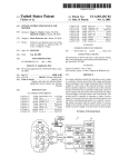
US 20140366898A1
(19) United States
(12) Patent Application Publication (10) Pub. No.: US 2014/0366898 A1
MONSEES et al.
(54)
(43) Pub. Date:
MULTIPLE HEATING ELEMENTS WITH
SEPARATE VAPORIZABLE MATERIALS IN
AN ELECTRIC VAPORIZATION DEVICE
Publication Classi?cation
(51)
Int- Cl
A24F 47/00
(71) Applicant: PLOOM, INC., SAN FRANCISCO, CA
Dec. 18, 2014
(2006.01)
(52) US, Cl,
(Us)
CPC .................................. .. A24F 47/008 (2013.01)
USPC
........................................................ ..
131/329
(72) Inventors: James MONSEES, San Francisco, CA
(US); Adam BOWEN, San Francisco,
CA (Us)
(57)
(21)
A cartridge for use With a vaporization device comprising a
APPI- NOJ 14/304,847
_
ABSTRACT
?rst heating element, a ?rst compartment for containment of
(22)
Flled:
Jun“ 13’ 2014
a ?rst vaporizable material, and a second compartment for
(60)
Related U's' Apphcatlon Data
Provisional application No. 61/835,458, ?led on Jun.
14, 2013.
.
.
containment of a second vaporizable material, Wherein the
device generates an aerosol for inhalation by a subject by
heating the ?rst vaporizable material or the second vaporiz
able material.
'/—100
[-18
Patent Application Publication
Dec. 18, 2014 Sheet 1 0f 8
2‘iT f"?
f if
I 5
10
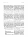
26
11
FIG. 1
’214
US 2014/0366898 A1
Patent Application Publication
Dec. 18, 2014 Sheet 2 0f 8
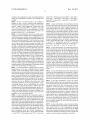
17
\ Ffk\wf
11
12
26
FIG. 2
US 2014/0366898 A1
14
Patent Application Publication
Dec. 18, 2014 Sheet 3 0f 8
US 2014/0366898 A1
Patent Application Publication
Dec. 18, 2014 Sheet 4 0f 8
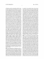
FIG. 4
US 2014/0366898 A1
Patent Application Publication
K18
Dec. 18, 2014 Sheet 5 0f 8
US 2014/0366898 A1
\70
K10
Y FIG.5
\15 90
22/
Patent Application Publication
Dec. 18, 2014 Sheet 6 0f 8
US 2014/0366898 A1
\
@A r14
%§
%%
“\k
%
%a}: 4116
May §
%
1061/
i \108
g
k
,%
7%
11b\%
3.
10b\/ ‘
g
_
&
24€i>19 >' FIG. 6
A 24b
g
3/
/
/11b
\é /\ 10b
K18
MA
Patent Application Publication
Dec. 18, 2014 Sheet 7 0f 8
US 2014/0366898 A1
x
r14
11%
“K
411a
10
3%
10a
%
R
‘
25a
19
{\25b
10b
10b
11b\g_3_
_£
11b
kw
Mi
> FIG.7
Patent Application Publication
Dec. 18, 2014 Sheet 8 0f 8
US 2014/0366898 A1
10a
AI
\ 236]»
if
xxx xxxx xx 22*“
10b
11b
M
P
W
19
> FIG. 8
Dec. 18, 2014
US 2014/0366898 A1
MULTIPLE HEATING ELEMENTS WITH
SEPARATE VAPORIZABLE MATERIALS IN
AN ELECTRIC VAPORIZATION DEVICE
fourth end of the second wire exit the second compartment
and couple electrically to the body.
[0006]
In some embodiments the device is be con?gured so
that the ?rst wicking material and the second wicking mate
CROSS-REFERENCE TO RELATED
APPLICATIONS
[0001] This application claims the bene?t of US. Applica
tion Ser. No. 61/835,458, ?led Jun. 14, 2013, which is hereby
incorporated by reference in its entirety.
SUMMARY OF THE INVENTION
[0002]
Devices and methods for electronic vaporization
having a ?rst heating element, a ?rst compartment for con
tainment of a ?rst vaporizable material, and a second com
partment for containment of a second vaporizable material
wherein the device and methods generate an aerosol for inha
lation by a subject by heating the ?rst vaporizable material or
the second vaporizable material.
[0003] In some aspects provided herein is a device for gen
erating an inhalable aerosol comprising: a detachable car
tridge comprising, a ?rst compartment for containment of a
?rst vaporizable material, a ?rst heating element, and a sec
ond compartment for containment of a second vaporizable
material, wherein the ?rst vaporizable material in the ?rst
rial have the same material properties or different material
properties, same or different wicking properties, have the
same wicking rate or different wicking rate due to the wicking
properties of the ?rst wicking material and the second wick
ing material, and the same wicking rate or different wicking
rate due to con?gurations of the circuitry.
[0007] In some embodiments the device is be con?gured so
that the ?rst compartment and the second compartment are in
series within the detachable cartridge relative to an air?ow
path, the ?rst compartment and the second compartment are
in parallel within the detachable cartridge relative to an air
?ow path, and the ?rst compartment and the second compart
ment share a common axis within the detachable cartridge. In
some embodiments the common axis is aligned with a central
axis of an air?ow path. In some embodiments the second
compartment are stacked, concentric, aligned around a cen
tral axis, or in a parallel alignment within the detachable
cartridge.
[0008] In some embodiments the ?rst compartment and the
second compartment are removable from the cartridge. In
some embodiments the ?rst compartment and the second
compartment is the same or different as the second vaporiz
compartment are replaceable with a third compartment or a
able material in the second compartment; and a body having
a battery and circuitry for controlling the device, wherein the
detachable cartridge and body are coupled by a ?rst connec
tion mechanism and wherein the ?rst heating element is con
?gured to vaporize the ?rst vaporizable material. In some
embodiments the device further comprises a second heating
element, wherein the second heating element is con?gured to
vaporize the second vaporizable material. In some embodi
ments, the device is con?gured so that the ?rst heating ele
ment is con?gured to vaporize the second vaporizable mate
fourth compartment in the cartridge.
rial. In some embodiments, the device is con?gured so that
the ?rst heating element comprises a resistive heater circuit or
the second heating element comprises a resistive heater cir
cuit.
[0004] In some embodiments, the device is con?gured so
that the ?rst heating element is con?gured to heat to a ?rst
target temperature, and the second heating element is con?g
ured to heat to a second target temperature. Examples of ?rst
and second target temperatures include but are not limited to
from about 100° to about 300° C., from about 125° to about
255° C., from about 150° to about 230° C., from about 170°
to about 210° C. In some embodiments the ?rst target tem
perature is different from the second target temperature.
[0005] In some embodiments the device is be con?gured so
that the ?rst heating element comprises a ?rst wire having a
?rst end and a second end, the ?rst wire in contact with the
?rst wicking material, wherein the ?rst wicking material is in
?uid communication with the ?rst vaporizable material. In
some embodiments the ?rst heating element is in the ?rst
compartment and wherein the ?rst end and the second end of
[0009] In some embodiments the device is con?gured so
that the connection mechanism comprises: a threaded con
nection; a tapered connection; a magnetic connection; a
spring-loaded connection; a spring detent connection; a snap
?t connection; a compression connection; or any combination
thereof.
[0010]
In some embodiments the device is con?gured so
that the body further comprises at least one push button for
operator control of the circuitry.
[0011]
In some embodiments the device is con?gured so
that the ?rst compartment comprises a ?rst air?ow path, and
the second compartment has a second air?ow path that is in
communication with the ?rst air?ow path. In some embodi
ments the ?rst compartment comprises a ?rst air?ow path,
and the second compartment has a second air?ow path,
wherein ?rst vapor from the ?rst air?ow path is introduced to
second vapor from the second air?ow path prior to exiting the
cartridge. In some embodiments the ?rst compartment com
prises a ?rst chamber comprising the ?rst air?ow path, and the
second compartment comprises a second chamber compris
ing the second air?ow path, wherein introduction of the ?rst
vapor to the second vapor occurs in the second chamber. In
some embodiments the cartridge comprises a third chamber
and introduction of the ?rst vapor to the second vapor occurs
in the chamber. In some embodiments the cartridge further
comprises a mouthpiece.
[0012] In some embodiments the device is con?gured so
that the vaporizable material comprises a liquid, a gel, a
viscous material, a temperature sensitive mesophase mate
the ?rst wire exit the ?rst compartment and couple electrically
rial, or a combination thereof. In some embodiments the ?rst
to the body. In some embodiments of at least one aspect the
vaporizable material or the second vaporizable material com
second heating element comprises a second wire having a
third end and a fourth end, the second wire in contact with the
prise: nicotine; ?avorants; humectants; water; or a combina
tion thereof.
second wicking material, wherein the second wicking mate
[0013] In some embodiments the device is con?gured so
that the circuitry includes an accelerometer. In some embodi
rial is in ?uid communication with the second vaporizable
material. In some embodiments the second heating element is
in the second compartment and wherein the third end and the
ments the accelerometer functions comprise: determining if a
user is actively using the device; providing a battery power
Dec. 18, 2014
US 2014/0366898 A1
level feedback of the device to the user; providing the user
with a mechanism to change a mode of the device; providing
an automatic activation mode when the device is picked up by
the user; providing a selective pre-heat mode for the resistive
heating elements; and providing an automatic sleep mode
when the device is inactive for a period of time.
[0014]
In some embodiments the device is con?gured so
that the cartridge is available in 2-compartment modules,
3-compartment modules, or multi-compartment modules.
[0015] In some embodiments the device is con?gured so
that the device comprises a ?rst capacitive sensing zone and a
second capacitive sensing zone, wherein the ?rst zone is
electrically isolated from the second zone, and wherein the
?rst zone comprises a ?rst capacitive sensor and the second
zone comprises a second capacitive sensor. In some embodi
ments the ?rst zone and second zone are con?gured so that
when the ?rst zone and second zone are contacted by a user,
the device communicates information to the user, the infor
mation comprising, a battery charge level, a vaporizable
material level, a pre-heat state, or a combination thereof. In
some embodiments the ?rst zone and second zone are con
?gured so that when a user swipes a ?nger from the ?rst zone
to the second zone or from the second zone to the ?rst zone,
the device communicates information to the user, the infor
about 125° to about 255° C., from about 150° to about 230°
C., from about 170° to about 210° C.
[0018] In some embodiments the cartridge is con?gured so
that a ?rst wicking material, wherein the ?rst heating element
comprises a ?rst wire having a ?rst end and a second end in
contact with the ?rst wicking material, wherein the ?rst wick
ing material is in ?uid communication with the ?rst vaporiz
able material. In some embodiments the cartridge is con?g
ured so that the ?rst heating element is in the ?rst
compartment and wherein the ?rst end and the second end of
the ?rst wire exits the ?rst compartment and couple electri
cally to the body.
[0019] In some embodiments the cartridge is con?gured so
that the second heating element comprises a second wire
having a third end and a fourth end in contact with the second
wicking material, wherein the second wicking material is in
?uid communication with the second vaporizable material. In
some embodiments the cartridge is con?gured so that the
second heating element is in the second compartment and
wherein the third end and the fourth end of the second wire
exits the second compartment and couple electrically to a
battery of the device.
[0020] In some embodiments the cartridge is con?gured so
that the ?rst wicking material and the second wicking mate
mation comprising, a battery charge level, a vaporizable
rial have the same material properties or different material
material level, a pre-heat state, or a combination thereof. In
properties. In some embodiments the cartridge is con?gured
so that the ?rst wicking material and the second wicking
some embodiments the ?rst zone and second zone are con
?gured so that when a user swipes a ?nger from the ?rst zone
to the second zone or from the second zone to the ?rst zone,
the device is activated.
[0016] In some aspects provided herein is a cartridge for
use with a vaporization device comprising: a ?rst vaporizable
material, a ?rst compartment that contains the ?rst vaporiz
able material, a ?rst heating element, a second vaporizable
material, and a second compartment that contains the second
vaporizable material, wherein the ?rst vaporizable material in
the ?rst compartment is the same as or different from the
second vaporizable material in the second compartment,
wherein the cartridge comprises a ?rst portion of a ?rst con
nection mechanism for detachable connection to a body of the
vaporization device, and wherein the ?rst heating element is
con?gured to vaporize the ?rst vaporizable material. In some
embodiments the cartridge is con?gured so that the second
heating element is con?gured to vaporize the second vapor
material have the same wicking properties or different wick
ing properties. In some embodiments the ?rst wicking mate
rial and the second wicking material have the same wicking
rate or different wicking rate due to the wicking properties of
the ?rst wicking material and the second wicking material. In
some embodiments the cartridge is con?gured so that the ?rst
wicking material and the second wicking material have the
same wicking rate or different wicking rate due to differences
between the ?rst vaporizable material and the second vapor
izable material.
[0021] In some embodiments the cartridge is con?gured so
that the ?rst compartment and the second compartment are in
series within the cartridge relative to an air?ow path. In some
embodiments the cartridge is con?gured so that the ?rst com
partment and the second compartment are in parallel within
the cartridge relative to an air?ow path. In some embodiments
the cartridge is con?gured so that the ?rst compartment and
izable material. In some embodiments the cartridge is con
the second compartment share a common axis within the
?gured so that the ?rst heating element is con?gured to vapor
ize the second vaporizable material. In some embodiments
the cartridge is con?gured so that the ?rst heating element
detachable cartridge. In some embodiments the cartridge is
comprises a resistive heater circuit. In some embodiments the
cartridge is con?gured so that the second heating element
comprises a resistive heater circuit. In some embodiments the
cartridge is con?gured so that the ?rst heating element is
con?gured to heat to a ?rst target temperature, and the second
heating element is con?gured to heated to a second target
temperature that is different from the ?rst target temperature,
wherein the ?rst heating element material properties are dif
ferent than the second heating element material properties.
[0017] In some embodiments the cartridge is con?gured so
that the ?rst target temperature is from about 100° to about
300° C., from about 125° to about 255° C., from about 150°
to about 230° C., from about 170° to about 210° C. In some
embodiments the cartridge is con?gured so that the second
target temperature is from about 100° to about 300° C., from
con?gured so that the common axis is aligned with a central
axis of an air?ow path. In some embodiments the cartridge is
con?gured so that the ?rst compartment and the second com
partment are stacked, concentric, aligned around a central
axis, or in a parallel alignment within the detachable car
tridge.
[0022]
The cartridge of claim 34, wherein the ?rst compart
ment and the second compartment are removable from the
cartridge. In some embodiments the ?rst compartment and
the second compartment are replaceable with a third compart
ment or a fourth compartment in the cartridge.
[0023] In some embodiments the cartridge is con?gured so
that the ?rst connection mechanism comprises: a threaded
connection; a tapered connection; a magnetic connection; a
spring-loaded connection; a spring detent connection; a snap
?t connection; a compression connection; or any combination
thereof.
Dec. 18, 2014
US 2014/0366898 A1
[0024]
In some embodiments the cartridge is con?gured so
that the cartridge further comprises a mouthpiece.
[0025] In some embodiments the cartridge is con?gured so
that the ?rst compartment comprises a ?rst air?ow path, and
the second compartment has a second air?ow path that is in
communication with the ?rst air?ow path. In some embodi
ments the ?rst compartment comprises a ?rst air?ow path,
and the second compartment has a second air?ow path,
wherein ?rst vapor from the ?rst air?ow path is introduced to
second vapor from the second air?ow path prior to exiting the
cartridge. In some embodiments the ?rst compartment com
prises a ?rst chamber comprising the ?rst air?ow path, and the
second compartment comprises a second chamber compris
ing the second air?ow path, wherein introduction of the ?rst
vapor to the second vapor occurs in the second chamber. In
some embodiments the cartridge comprises a third chamber
and introduction of the ?rst vapor to the second vapor occurs
[0034] In some embodiments the ?rst heating element is
con?gured to heat to a ?rst target temperature, and the second
heating element is con?gured to heat to a second target tem
perature. Examples of ?rst and second target temperatures
include but are not limited to from about 100° to about 300°
C., from about 125° to about 255° C., from about 150° to
about 230° C., from about 170° to about 210° C. In some
embodiments the ?rst target temperature is different from the
second target temperature.
[0035] In some embodiments the device is be con?gured so
that the ?rst heating element comprises a ?rst wire having a
?rst end and a second end, the ?rst wire in contact with the
?rst wicking material, wherein the ?rst wicking material is in
?uid communication with the ?rst vaporizable material. In
some embodiments the ?rst heating element is in the ?rst
compartment and wherein the ?rst end and the second end of
the ?rst wire exit the ?rst compartment and couple electrically
in the chamber.
[0026] In some embodiments of any aspect the device, car
tridge or method comprises a pre-heat temperature for the
?rst heating element or the second hearing element is from
about 100° C. to about 130° C.
[0027] In some embodiments the cartridge is con?gured so
that the vaporizable material comprises a liquid, a gel, a
viscous material, a temperature sensitive mesophase mate
rial is in ?uid communication with the second vaporizable
material. In some embodiments the second heating element is
in the second compartment and wherein the third end and the
fourth end of the second wire exit the second compartment
rial, or a combination thereof. In some embodiments the ?rst
and couple electrically to the body.
to the body. In some embodiments of at least one aspect the
second heating element comprises a second wire having a
third end and a fourth end, the second wire in contact with the
second wicking material, wherein the second wicking mate
vaporizable material or the second vaporizable material com
[0036]
prise: nicotine; ?avorants; humectants; water; or a combina
tion thereof. In some embodiments the cartridge is available
that the ?rst wicking material and the second wicking mate
in 2-compartment modules, 3-compartment modules, or
multi-compartment modules.
[0028] In some aspects provided herein is a method of
generating an aerosol comprising: providing an aerosol gen
erating device comprising: a cartridge comprising, a ?rst
vaporizable material, a ?rst compartment that contains the
?rst vaporizable material, a ?rst heating element, a second
vaporizable material, and a second compartment that contains
the second vaporizable material, wherein the ?rst vaporizable
material in the ?rst compartment is the same or different as
the second vaporizable material in the second compartment;
and a body having a battery and circuitry for controlling the
device, wherein the detachable cartridge and body are
coupled by a ?rst connection mechanism and wherein the ?rst
In some embodiments the device is be con?gured so
rial have the same material properties or different material
properties, same or different wicking properties, have the
same wicking rate or different wicking rate due to the wicking
properties of the ?rst wicking material and the second wick
ing material, and the same wicking rate or different wicking
rate due to con?gurations of the circuitry.
[0037] In some embodiments the device is be con?gured so
that the ?rst compartment and the second compartment are in
series within the detachable cartridge relative to an air?ow
path, the ?rst compartment and the second compartment are
in parallel within the detachable cartridge relative to an air
?ow path, and the ?rst compartment and the second compart
heating element is con?gured to vaporize the ?rst vaporizable
ment share a common axis within the detachable cartridge. In
some embodiments the common axis is aligned with a central
axis of an air?ow path. In some embodiments the second
compartment are stacked, concentric, aligned around a cen
material, wherein the device is con?gured to
tral axis, or in a parallel alignment within the detachable
[0029] generate a ?rst aerosol in a ?rst air?ow path from
the ?rst vaporizable material, generate a second aerosol
from the second vaporizable material in the ?rst air?ow
path or a second air?ow path, and deliver the ?rst aerosol
cartridge.
[0038] In some embodiments the ?rst compartment and the
second compartment are removable from the cartridge. In
some embodiments the ?rst compartment and the second
and the second aerosol to a user, or
compartment are replaceable with a third compartment or a
[003 0] generate a ?rst vapor in a ?rst air?ow path from
the ?rst vaporizable material, generate a second vapor
from the second vaporizable material in the ?rst air
fourth compartment in the cartridge.
[0039] In some embodiments the connection mechanism
comprises: a threaded connection; a tapered connection; a
?ow path or a second air?ow path, and deliver to a
magnetic connection; a spring-loaded connection; a spring
user
detent connection; a snap-?t connection; a compression con
nection; or any combination thereof.
[0031]
a third aerosol comprising condensate of the
?rst vapor and the second vapor or
[0032] a fourth aerosol generated from a third
vapor, the third vapor formed when the ?rst vapor is
introduced to the second vapor or condensate
thereof, or
[0033] a ?fth aerosol generated when the ?rst aero
sol is introduced to the second vapor or condensate
thereof.
[0040] In some embodiments the body further comprises at
least one push button for operator control of the circuitry.
[0041] In some embodiments the ?rst compartment com
prises a ?rst air?ow path, and the second compartment has a
second air?ow path that is in communication with the ?rst
air?ow path. In some embodiments the ?rst compartment
comprises a ?rst air?ow path, and the second compartment
has a second air?ow path, wherein ?rst vapor from the ?rst
Dec. 18, 2014
US 2014/0366898 A1
air?ow path is introduced to second vapor from the second
air?ow path prior to exiting the cartridge. In some embodi
ments the ?rst compartment comprises a ?rst chamber com
prising the ?rst air?ow path, and the second compartment
comprises a second chamber comprising the second air?ow
path, wherein introduction of the ?rst vapor to the second
vapor occurs in the second chamber. In some embodiments
the cartridge comprises a third chamber and introduction of
the ?rst vapor to the second vapor occurs in the chamber. In
some embodiments the cartridge further comprises a mouth
piece.
[0042] In some embodiments the vaporizable material
comprises a liquid, a gel, a viscous material, a temperature
sensitive mesophase material, or a combination thereof. In
some embodiments the ?rst vaporizable material or the sec
ond vaporizable material comprise: nicotine; ?avorants;
humectants; water; or a combination thereof.
[0043] In some embodiments the ?rst compartment com
prises the ?rst air?ow path, and the second compartment
comprises the second air?ow path that is in communication
with the ?rst air?ow path.
[0044]
In some embodiments the ?rst compartment com
BRIEF DESCRIPTION OF THE DRAWINGS
[0054]
The novel features of the invention are set forth with
particularity in the appended claims. A better understanding
of the features and advantages of the present invention will be
obtained by reference to the following detailed description
that sets forth illustrative embodiments, in which the prin
ciples of the invention are utilized, and the accompanying
drawings of which:
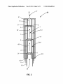
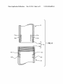
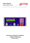
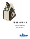
[0055]
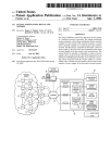
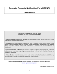
FIG. 1 illustrates a sectional view of a detachable
cartridge having a ?rst heating element, a second heating
element, a ?rst compartment for containment of vaporizable
material, and a second compartment for containment of
vaporizable material;
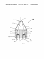
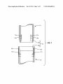
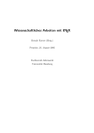
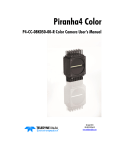
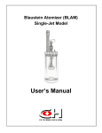
[0056]
FIG. 2 illustrates a sectional view of a detachable
cartridge having a second heating element, a third heating
elements, a ?rst compartment for containment of vaporizable
material, a second compartment for containment of vaporiZ
able material, and a third compartment for containment of
vaporizable material;
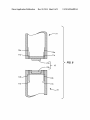
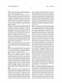
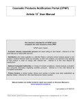
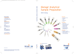
[0057]
FIG. 3 illustrates a sectional view of a detachable
cartridge having two heating elements and two compartments
for containment of vaporizable material in a parallel or con
prises the ?rst air?ow path, and the second compartment
comprises the second air?ow path, wherein the device is
centric con?guration;
con?gured to introduce the ?rst vapor or condensate thereof
from the ?rst air?ow path to second vapor or condensate
invention with dimensions and aspect ratio similar to a con
thereof from the second air?ow path prior to exiting the
cartridge.
[0045]
In some embodiments the ?rst compartment com
prises a ?rst chamber comprising the ?rst air?ow path, and the
second compartment comprises a second chamber compris
ing the second air?ow path, wherein introduction of the ?rst
vapor of condensate thereof to the second vapor or conden
sate thereof occurs in the second chamber.
[0046]
In some embodiments the cartridge comprises a
third chamber and introduction of the ?rst vapor or conden
sate thereof to the second vapor or condensate thereof occurs
in the third chamber.
[0047] In some embodiments the cartridge further com
prises a mouthpiece.
[0048]
In some embodiments the ?rst vaporizable material
comprises water.
[0049]
In some embodiments the second vaporizable mate
rial comprises water.
[0050] In some embodiments the device is con?gured to
heat the ?rst vaporizable material to a lower temperature than
a second temperature to which the second vaporizable mate
rial is heated.
[0051] In some embodiments the device is con?gured to
heat the second vaporizable material to a lower temperature
than a second temperature to which the ?rst vaporizable mate
rial is heated.
[0052]
In some embodiments of at least one aspect
described above the device is con?gured so the device func
tions as a water-cooled smoking apparatus.
INCORPORATION BY REFERENCE
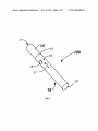
[0058]
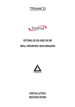
FIG. 4 illustrates an isometric representation of the
ventional cigarette.
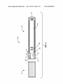
[0059] FIG. 5 illustrates a representative sectional view of
the inventive device described in FIG. 4.
[0060] FIGS. 6, 7 & 8 illustrate representative examples of
possible connection mechanisms for the inventive device.
DETAILED DESCRIPTION OF THE INVENTION
[0061] The invention described herein has a wide range of
applications for inhalation of an active substance as will be
appreciated by persons of skill in the art upon reviewing the
disclosure. For example, the devices, and cartridges (i.e.
pods), such as those disclosed in US. application Ser. No.
11/485,168, systems, kits and methods could be used, for
example, to inhale a tobacco product through the mouth or
nose. The devices, systems, kits and methods could be used,
for example, to inhale any substance, such as a botanical,
pharmaceutical, nutraceutical, or any other substance provid
ing a bene?t or sensation to an end user.
[0062] Further, active substances such as those disclosed in
US. application Ser. No. 14/271,071, similar formulations
and methods could be used, for example, providing a bene?t
or sensation to an end user.
[0063] Provided herein is a device for generating an inhal
able aerosol comprising; a detachable cartridge having a ?rst
heating element, a second heating element, a ?rst compart
ment for containment of vaporizable material, and a second
compartment for containment of vaporizable material,
wherein the vaporizable material in the ?rst compartment is
the same or different as the vaporizable material in the second
compartment, and a body having a battery and circuitry for
controlling the device wherein the cartridge and body are
coupled by a ?rst connection mechanism.
[0064] The detachable cartridge comprises multiple com
[0053] All publications, patents, and patent applications
partments with at least one compartment having at least one
mentioned in this speci?cation are herein incorporated by
heating element and at least one vaporizable material. The
reference to the same extent as if each individual publication,
device is con?gured such that each compartment containing
patent, or patent application was speci?cally and individually
indicated to be incorporated by reference in its entirety.
at least one resistive heating element also comprises a wick
ing material that is in direct contact with the vaporizable
Dec. 18, 2014
US 2014/0366898 A1
material in the compartment. At least one heating element in
at least one compartment is exposed to an air passage in the
cartridge.
[0065] At least one resistive heater in the cartridge is
designed to reach a closely controlled target temperature,
below the pyrolytic temperature of tobacco, and more spe
ci?cally, a target “vapor temperature”, greater than about
100° C., but less than about 300° C., intended to convert the
vaporizable material of at least one compartment to a visible
vapor, such as about 170° C. for ?avorants, about 190° C. for
nicotine, and about 210° C. for humectants.
[0066]
In some embodiments, at least one resistive heater
comprises wire coil wrapped aron a wicking material (e.g.
silica) that penetrates a moisture resistant liquid barrier of at
least one compartment holding the vaporizable material and
allows the vaporizable material to “wick” around the wire and
be heated to a controlled temperature when activated. This
occurs when the ends of wires traversing the length of the
cartridge, exiting the compartment distally and connecting to
about 210° C. for humectants, about 100° C., about 120° C.,
about 140° C., about 160° C., about 180° C., about 200° C.,
about 220° C., about 240° C., about 260° C., about 280° C.,
and about 300° C.
[0069]
In some embodiments, the vaporizable material in
the ?rst compartment is the same as the vaporizable material
in the second compartment, and the temperature range for the
?rst heating element is the same or different than the tem
perature range for the second heating element. In some
embodiments, the vaporizable material in the ?rst compart
ment is different than the vaporizable material in the second
compartment, and the temperature range for the ?rst heating
element is the same or different than the temperature range for
the second heating element. Temperatures ranges at least
comprise temperatures below the pyrolytic temperature of
tobacco, greater than about 100° C. but less than about 300°
C., about 170° C. for ?avorants, about 190° C. for nicotine,
about 210° C. for humectants, about 125° to about 255° C.,
about 150° to about 230° C., about 170° to about 210° C.
the body, are activated by a mechanism, optionally a button
[0070]
In some embodiments, the vaporizable material in
mechanism, and circuitry connected to the battery in the body.
Additionally, different wicking rates of the vaporizable mate
rial in the compartment is obtained using different wick mate
the ?rst compartment is the same as the vaporizable material
rials and/or different arrangements of the heating element and
the ?rst heating element is the same or different than the
the wick (e.g. heating element wrapped around the wick,
heating parameters for the second heating element. In some
embodiments the vaporizable material in the ?rst compart
ment is different than the vaporizable material in the second
heating element passing through the wick). Wicking materi
als at least comprise silica, cotton, stainless steel mesh, and
in the second compartment, and the heating parameters for
Ekowool. Wicking properties, which effect wicking rates,
compartment, and the heating parameters for the ?rst heating
include wicking material density, composition, dimension,
element is the same or different than the heating parameters
shape, size, length, width, among others. One of ordinary skill
in the art would recognize the relationship between wicking
material properties and arrangements of the heating element
comprise target temperature, temperature range, heating
duration, heating frequency, and heating control. One of ordi
for the second heating element. Heating parameters at least
nary skill in the art would recognize heating parameters that
effect function of the aerosol generating devices described
and the wick and the effects on wicking rates.
[0067] In some embodiments wicking material of the ?rst
heating element is the same or different than the wicking
herein.
material of the second heating element. Heating element
material properties include heating element material compo
[0071] In some embodiments, the resistive heater elements
within at least one compartment for containment of vaporiz
sition, density, dimension, shape, size, length, width, among
able material are “breath-activated” when the user puffs on
others. In some embodiments, the wicking material of the ?rst
heating element is the same as the wicking material of the
the device. This activation mode is accomplished by vacuum
second heating element and the wicking rate of the vaporiz
and circuitry connected to the battery in the attachable body.
activated contact switches and or solid state pressure sensors
able material in the ?rst compartment to at least one heating
element is the same or different as the wicking rate of the
vaporizable material in the second compartment to at least
one heating element. In some embodiments, the wicking
material of the ?rst heating element is different than the
wicking material of the second heating element, and the wick
ing rate of the vaporizable material in the ?rst compartment to
at least one heating element is the same or different as the
wicking rate of the vaporizable material in the second com
partment to at least one heating element.
[0068] In some embodiments the vaporizable material in
the ?rst compartment is the same as the vaporizable material
in the second compartment, and the target temperature for the
?rst heating element is the same or different as the target
temperature for the second heating element. In some embodi
ments, the vaporizable material in the ?rst compartment is
different than the vaporizable material in the second compart
ment, and the target temperature for the ?rst heating element
[0072] In still other embodiments, at least one resistive
heater element within at least one compartment for contain
ment ofvaporizable material is selectively activated when the
user picks up the device. This activation mode is accom
plished by a button mechanism, an accelerometer, and/or
solid state sensors and circuitry connected to the battery in the
attachable body. The selective activation cycle has several
modes including but not limited to a “preheat” setting for the
resistive heaters that brings the temperature of at least one
resistive heater up to a “pre-vaporization” temperature (e. g.:
100°-130° C.); a sleep mode where the device deactivates and
shuts down after a short period of time; or an “off” mode when
no use or movement is detected for a longer period of time, or
the user manual changes the mode and/ or deactivates the
device with the button.
[0073]
In some embodiments, at least one resistive heater
wire is inserted through or surrounded by wicking material in
is the same or different as the target temperature for the
direct contact with one of the compartments containing
second heating element. Target temperatures at least com
vaporizable material. The ends of wires traverse the length
and exit the compartment distally where they attach to a ?rst
connection mechanism in the distal end of the cartridge that
prise temperatures below the pyrolytic temperature of
tobacco, greater than about 100° C. but less than about 300°
C., about 170° C. for ?avorants, about 190° C. for nicotine,
matches a second connection mechanism on the body.
Dec. 18, 2014
US 2014/0366898 A1
[0074]
In some embodiments, the detachable cartridge is a
single-unit construction wherein the entire cartridge with all
of its components, are replaced en masse.
[0075] In some embodiments, the detachable cartridge is a
modular construction wherein the ?rst and/or second com
nism. An exemplary device 100 is illustrated in FIG. 4 com
prising a detachable cartridge 14, having an air outlet 17,
internal compartments for containment of vaporizable mate
rial (not shown), heating elements (not shown), at least one air
inlet (not shown), and a ?rst connection mechanism 19. Also
vaporizable material and a heater, are removable. In some
included is a body 18 comprising an activation button 15, an
air inlet 16, a second connection mechanism 19, an optional
glow indicator LED 20, a mode indicator LED 21, an internal
embodiments, the individual compartments and heaters are
battery (not shown), an optional accelerometer (not shown),
partments containing vaporizable material and a heater, or
combinations of multiple compartments, each containing
arranged in a stacked-series con?guration, a parallel con?gu
and internal circuit board and circuitry (not shown). In some
ration, a concentric con?guration, or any combination of
embodiments a detachable mouthpiece comprises the car
tridge 14. In some embodiments a detachable mouthpiece is
series-stacked, parallel or concentric con?guration within the
detachable cartridge.
[0076] In some embodiments, the individual compartments
containing the vaporizable materials and heaters within the
cartridge are removable and replaceable. In still other
embodiments the individual compartments containing the
vaporizable materials and heaters within the cartridge are
interchangeable with replacement components. In some
embodiments, the individual compartments containing the
vaporizable materials and heaters within the cartridge are
recyclable and reusable and is re?lled by the user.
[0077] In some embodiments, the device comprises differ
ent connection mechanisms between the detachable cartridge
and the body. In some embodiments, the connection mecha
nisms comprise; a threaded connection, a tapered connection,
a magnetic connection, a spring-loaded connection, a spring
detent connection, a snap-?t connection, a compression con
nection, or any combination thereof.
[0078] In some embodiments, the body also comprises at
least one push button for operator control of the circuitry. In
some embodiments, the body also comprises at least one LED
indicator to apprise the user of a functional operation of the
device.
[0079] In some embodiments the battery is not recharge
able. In some embodiments the battery is rechargeable. In
some embodiments the battery is a lithium-based recharge
able battery. In some embodiments the attachable body com
prises a mechanism for recharging the battery.
[0080] In some embodiments the device is con?gured to
further comprise a detachable mouthpiece, wherein the
mouthpiece is the detachable cartridge. In some embodi
ments the mouthpiece has at least one air passage there
through and at least one heating element is exposed to the air
passage. In some embodiments the detachable mouthpiece
cartridge is a single-unit, non-modular construction. In some
the cartridge 14.
[0082] As shown in FIG. 4, the halves of the exemplary
device form a separable, but ?rm connection 19 and resemble
a typical cigarette in appearance. The connection mechanism
19, also interchangeably referred to as an attachment mecha
nism, is achieved in numerous ways. As shown in FIGS. 6, 7,
8, an attachment mechanism 19 may include and be herein
represented by, but are not limited to, a threaded connection
24a, 24b, a tapered connection 25a, 25b, a magnetic connec
tion 23a, 23b, as illustrative examples, or, a spring-loaded
connection (not shown), a spring detent connection (not
shown), a snap-?t connection (not shown), a compression
connection (not shown), or any combination thereof. In some
instances, the device 100 is manufactured as a single-use
inseparable outer body. In some embodiments, the single
button interface 15 provides the mechanism for on, off and
wake from sleep. Altematively, an accelerometer (not
shown), provides the mechanism for on, off and wake from
sleep. In some embodiments, the single button interface also
provides the mechanism for selection of speci?c heater acti
vation within the cartridge. In some embodiments, (not
shown) additional buttons are included for any of these func
tions. For example, pressing the single button for 1 second
turns the device on. Continuing to hold the button for 5
seconds disables the motion-based low power standby and
automatic shut-down. Alternatively, a second button is used to
disable the motion-based low power standby and and/or shut
down. In some embodiments, upon power-up, if the single
button is depressed for a very long period (>10 seconds), the
device turns off again. This is to prevent inadvertent activa
tion while in a purse, etc. While on, pressing the button
momentarily turns it off. In some embodiments, a single or
more than one button could report battery level (via LED
blinks, for instance), change operating temperature of the
embodiments the compartments for containment of vaporiZ
device, or change the nominal intensity of the LED(s)iif the
able material are aligned in series within the detachable
user is in a dark environment and does not want the light to be
mouthpiece cartridge, are aligned in parallel within the
detachable mouthpiece cartridge, are aligned concentrically
within the detachable mouthpiece cartridge, and/or are
aligned in any combination of series stacking, concentric, and
parallel alignment within the detachable mouthpiece car
tridge.
[0081] Provided herein is a device for generating an inhal
able aerosol comprising; a detachable cartridge having a ?rst
heating element, a second heating element, a ?rst compart
ment for containment of vaporizable material, and a second
distracting. These various features could be triggered with
one or more buttons or with the same button by pressing it for
a prescribed duration or number of presses.
[0083]
Provided herein is a device for generating an inhal
able aerosol, comprising; a detachable cartridge having a ?rst
heating element, a second heating element, a ?rst compart
ment for containment of vaporizable material, and a second
compartment for containment of vaporizable material,
wherein the vaporizable material in the ?rst compartment is
the same or different as the vaporizable material in the second
compartment for containment of vaporizable material,
compartment; and a body having a battery, at least one acti
wherein the vaporizable material in the ?rst compartment is
vation button, and circuitry for controlling the device,
the same or different as the vaporizable material in the second
wherein the device comprises a ?rst capacitive sensor
coupled to the circuitry. In some embodiments, a surface or
shell of the device triggers the ?rst capacitive sensor upon a
compartment; and an attachable body having a battery and
circuitry for controlling the device wherein the detachable
cartridge and body are coupled by a ?rst connection mecha
user input to the surface or shell of the device. In some
US 2014/0366898 A1
Dec. 18, 2014
embodiments, a capacitive sensing surface of the ?rst capaci
4, respectively. One exemplary design of these resistive
tive sensor detects when a user is holding the device, causing
heater elements 3, 4 include wire coils 31, 41 wrapped around
the device to indicate that the device is in use or a ready state.
a silica wick 9. The wire coils 31, 41 are coupled to heater
In some embodiments, the circuitry causes the heating ele
circuit wires 10, 11 (alternatively called heater wires herein),
ments to enter a pre-heat state upon activation or triggering of
the ?rst capacitive sensor. In some embodiments, the device
which deliver energy to the coils 31, 41 which results in the
exits the pre-heat state or turns off when the ?rst capacitive
coils heating up and aerosolizing the liquid vaporizable mate
rial wicked by the wicking material 9 from their respective
sensor no longer detects movement of the device. In some
compartments 114 or 214. While the wires 10, 11 are
embodiments, a surface of the device comprises two electri
cally isolated capacitive sensing zones wherein the ?rst zone
described herein as being coupled to coils 31, 41, other
designs of these heating elements are contemplated herein
comprises s ?rst capacitive sensor, and the second zone com
prises a second capacitive sensor. In some embodiments,
which would be obvious to one of ordinary skill in the art
when a user contacts a ?rst zone, the device indicates to the
user that the device is in use or in a ready state. In some
embodiments, the device indicates use or ready state by dis
playing a pattern of one or more LED(s), displaying a prede
upon reading the disclosure herein. Further, other wick mate
rials are envisioned and must be capable of withstanding the
target temperatures generated by the resistive heating ele
ment, without changing the ?avor of the vapor or imparting an
undesirable taste to the end user. The wicking material 9,
termined color of one or more LED(s), or provides an audio
extends through the inner liquid barrier walls 13, along with
signal. In some embodiments, the zones are con?gured such
the heater circuit wires 1 0, 1 1 for the resistive heater elements
that when a user touches one of the zones in a predetermined
3, 4. This provides a steady and even ?ow of liquid vaporiz
pattern of one or more touches, the device displays a charge
level of the battery with a pattern of one or more LED(s) or
able material to the resistive heater elements 3, 4 until the
vaporizable material within at least one compartment is
with a color of one or more LED(s), or with an audio signal.
exhausted. Immediately proximal to each heater element 3, 4,
In some embodiments, the zones are con?gured such that
when a user swipes a ?nger from the ?rst zone to the second
zone, or from the second zone to the ?rst zone, the device
displays a charge level of the battery with a pattern of one or
and in the central airpath, is an atomizing chamber 61, 62
where the vapor generated from the heating element will form
and mix with inlet air and the vapors formed from any previ
ous heating elements in the airpath 1. In addition, the heater
element circuit wires 10, 11 may extend either through, or
more LED(s) or with a color of one or more LED(s), or with
an audio signal. In some embodiments the device is con?g
ured to further comprise a detachable mouthpiece, wherein
the mouthpiece is the detachable cartridge. In some embodi
ments the mouthpiece has at least one air passage there
through and at least one heating element is exposed to the air
passage. In some embodiments the detachable mouthpiece
cartridge is a single-unit, non-modular construction. In some
embodiments the compartments for containment of vaporiz
able material are aligned in series within the detachable
mouthpiece cartridge, are aligned in parallel within the
detachable mouthpiece cartridge, are aligned concentrically
within the detachable mouthpiece cartridge, and/or are
aligned in any combination of series stacking, concentric, and
parallel alignment within the detachable mouthpiece car
tridge. In some embodiments, touching the device to lips of a
user activates a second capacitive sensor coupled to the cir
cuitry whereby the device heating elements enter a pre-heat
state. In some embodiments, when the user inhales the heat
ing elements get fully activated and generate aerosol that is
deliverable to the user by such inhalation or by additional
inhalation. In some embodiments, inhalation activates a pres
sure switch to fully activate the heater elements. In some
embodiments, the device comprises a button or touch sensor
that when pushed or touched fully activates the heater ele
ments and generates aerosol that is deliverable to a user by
inhalation thereby.
[0084] As described herein and further shown in FIG. 1,
one exemplary illustration of the detachable cartridge 14
comprises a shell or outer housing 2, having a single central
airpath 1 therethrough with an air inlet 26 and air outlet, 17,
and a ?rst and second stacked compartments 114, 214,
respectively, each surrounded by a liquid barrier 13, and ?lled
with an absorbent batting material 6, 7 that will absorb and
hold a ?rst and second vaporizable material. The vaporizable
materials in the stacked compartments 114, 214 is the same or
different. Also within each cartridge, and centered within the
central airpath is a ?rst and second resistive heater element 3,
along side of, adjacent compartments 114, 214 until they
reach the ?rst connection mechanism (not shown) at the distal
end of the detachable cartridge 14. The wires then couple to
the circuitry of the device which controls the activation and
other features of the heater elements, and thus control the
timing, delivery, contents, and amount, at least, of the vapor or
aerosol deliverable to the user. In some embodiments a
detachable mouthpiece comprises the cartridge 14. In some
embodiments a detachable mouthpiece is the cartridge 14.
[0085] In some embodiments of the detachable cartridge
14, as shown in FIG. 2, the cartridge 14 comprises a shell or
outer housing 2, having a single central airpath 1 there
through, a ?rst, second and third stacked compartments 114,
214, and 314, respectively, each surrounded by a liquid bar
rier 13, and ?lled with an absorbent batting material 6, 7, and
8 that will absorb and hold a ?rst, second and third vaporiz
able material. The vaporizable material in the ?rst, second
and third compartments is the same or different. Also within
each cartridge, and centered within the central airpath is a
?rst, second, and third resistive heater element 3, 4, and 5,
respectively. As described previously, an exemplary design of
these resistive heater elements 3, 4, and 5 include wire coils
31, 41, and 51 wrapped around a silica wick 9. The wicking
material 9, extends through the inner liquid barrier walls 13,
along with the circuit wires 10, 11, and 12 for the resistive
heater elements 3, 4 and 5. This provides a steady and even
?ow of liquid vaporizable material to the resistive heater
elements 3, 4 and 5 until the vaporizable material within at
least one compartment 114, 214, 314 is exhausted. Immedi
ately proximal to each heater coil 31, 41, and 51, and in the
central airpath, is an atomizing chamber 61, 62 and 63 where
the vapor generated from the heating element will form and
mix with inlet air and the vapors formed from any previous
heating elements in the airpath 1. In addition, the heater
element circuit wires 10, 11, and 12 may extend either
through, or along side of, adjacent compartments 114, 214,
and 314 until they reach the ?rst connection mechanism (not
Dec. 18, 2014
US 2014/0366898 A1
is the cartridge 14.
[0086] Still further, an additional exemplary illustration of
simple butted-end connection, with a pair of magnets 23a,
23b, (or a single magnet 23 and conductive counter-sunk
mating endplate. The heater circuit wires 10a, 1111 could be
inserted at various aligned point locations on the mating end
corresponding to the mating connections 10b, 11b in the
the detachable cartridge 14 as shown in FIG. 3 comprises a
attachable body (electronics and battery module).
shell or outer housing 2, having multiple air inlets 26a, 26b,
etc., and compartments, ultimately culminating into a single
[0090] One skilled in the art will quickly recognize that
based on the description herein, any combination of cartridge
shown) at the distal end of the detachable cartridge 14. In
some embodiments a detachable mouthpiece comprises the
cartridge 14. In some embodiments a detachable mouthpiece
central airpath 1 at the air outlet, 17. The illustrative embodi
ment comprises two parallel or circumferentially located
compartments 114, 214, respectively, however, one skilled in
the art will recognize that there may be multiple circumfer
entially-located compartments; (e.g.: 3, 4, 5, etc.). The vapor
izable material in the ?rst and second compartments is the
same or different. The vaporizable material in multiple com
partments is the same or different. In some embodiments a
detachable mouthpiece comprises the cartridge 14. In some
embodiments a detachable mouthpiece is the cartridge 14.
[0087] The illustrative embodiment in FIG. 3 comprises
two parallel or circumferentially located compartments 114,
214, each surrounded by a liquid barrier 13, and ?lled with an
absorbent batting material 6, 7 that will absorb and hold a ?rst
and second vaporizable material. Also within each cartridge,
and centered within the respective airpaths 26a, 26b is a ?rst
and second resistive heater element 3, 4. As described previ
ously, the exemplary design of these resistive heater elements
3, 4 include wire coils 31, 41 wrapped around a silica wick 9.
The wicking material 9 extends through the inner liquid bar
rier walls 13, along with the circuit wires 10, 11 for the
resistive heater elements 3, 4. This provides a steady and even
?ow of liquid vaporizable material to the resistive heater
elements 3, 4 until the vaporizable material within at least one
and heater element circuit arrangement as described herein
would be possible for alternative cartridge embodiments.
[0091] One skilled in the art will quickly recognize that
based on the description herein, any combination of mouth
piece, cartridge and heater element circuit arrangement as
described herein would be possible for alternative mouth
piece and/ or cartridge embodiments.
[0092] Provided herein is a device 100 as shown in FIGS. 1,
2, 3 and 5 for generating an inhalable aerosol comprising; a
removable cartridge 14 having a proximal end and a distal
end, wherein, the removable cartridge 14 comprises; an outer
shell 2, a ?rst connection mechanism 19 at the distal end, at
least one air inlet in the distal end 26, a ?rst heating element
3 with circuitry 10, a second heating element with circuitry
11, a ?rst compartment containment of vaporizable material
114, a second compartment containment of vaporizable mate
rial 214, wherein the vaporizable material in the ?rst com
partment 114 is the same or different as the vaporizable mate
rial in the second compartment 214, at least one airpath 1
therethrough having exposure to at least one compartment for
containment of vaporizable material 114, 214 and at least one
heating element 3, 4, comprising heating coils 31, 41, a liquid
barrier 13 to isolate the vaporizable materials within at least
one compartment and from at least one airpath, an air outlet
compartment 114, 214 is exhausted. Immediately proximal to
each coil 31, 41, and in the respective airpath, is an atomizing
chamber 61, 62 where the vapor generated from the heating
17 at the proximal end; and a body 18 having a proximal end
and a distal end, coupleable to the cartridge with a second
element will form and mix with inlet air from the air inlets
26a, 26b. Ultimately, the airpaths converge into a central
outer shell 2, the second connection mechanism 19 at the
proximal end, an air inlet in the outer shell 16, at least one
atomizing chamber 64 within a single airpath 1, where the
vapors mix before exiting through the air outlet 17. In addi
tion, the heater element circuit wires 10, 11 extend through or
indicator light or mode indicator LED 20, 21, a battery 70,
circuitry 80, 90 for controlling the device, at least one opera
tor-controlled push-button 15 connected to the circuitry
through the outer shell, and an air outlet 27 in the proximal
along side of adj acent compartments 114, 214 until they reach
the ?rst connection mechanism (not shown) at the distal end
connection mechanism 19; wherein, the body comprises; an
end. In some embodiments a detachable mouthpiece com
of the detachable cartridge 14. In some embodiments a
prises the cartridge 14. In some embodiments a detachable
detachable mouthpiece comprises the cartridge 14. In some
embodiments a detachable mouthpiece is the cartridge 14.
[0088] As illustrated in FIGS. 6, 7, and 8 and brie?y
described previously, a plurality of connection mechanisms
are contemplated for the device which comprise threaded
mouthpiece is the cartridge 14.
[0093]
In some embodiments, the device for generating an
inhalable aerosol is an electronic cigarette 100. In some
embodiments, the device for generating an inhalable aerosol
is an electronic cigar (not shown). In some embodiments, the
connections 24a, 24b, tapered connections 25a, 25b, mag
device for generating an inhalable aerosol is an electronic
netic connections 23a, 23b, as illustrative examples, or, a
pipe (not shown). In some embodiments, the device for gen
spring-loaded connection (not shown), a spring detent con
nection (not shown), a snap-?t connection (not shown), a
compression connection (not shown), or any combination
erating an inhalable aerosol is an electronic water-cooled
thereof. The connectors shown in FIGS. 6, 7, and 8 could be
part of a detachable cartridge and/or a mouthpiece compris
at least one atomizing chamber 61, 62, 63, 64 adjacent and
proximal to the resistive heating elements 3, 4, 5 and heater
ing a detachable cartridge.
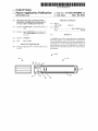
[0089] FIGS. 6 and 7 illustrate non-limiting examples for a
threaded connection 24a, 24b and (Morse) taper connection
25a, 25b respectively where the heater circuit wires 10a, 11a,
(and 12a in a 3-heater element design), could be inserted
along the inner diameters to speci?c longitudinal locations
smoking apparatus (not shown).
[0094]
Still further, the removable cartridge 14 comprises
coils 31, 41, 51. In some embodiments a detachable mouth
piece comprises the cartridge 14. In some embodiments a
detachable mouthpiece is the cartridge 14.
[0095] In some embodiments, the vaporizable material is a
liquid, a gel, a viscous material, a temperature sensitive
mesophase material.
corresponding to the mating connections 10b, 11b, (and 12b
[0096]
in a 3-heater element design), in the attachable body (elec
tronics and battery module). Similarly, FIG. 8 illustrates a
battery module cross-section of FIG. 5, in some embodiments
of the device, the circuitry controls the selection of the elec
As shown in the representative body/ electronics and
Dec. 18, 2014
US 2014/0366898 A1
tronic heaters to be activated. This may be accomplished in a
number of ways, including but not limited to push button
controls 15, having power supply wires 22 for coupling to the
heater wires extending to the ?rst connection mechanism 19,
pressure sensitive or solid state pressure switches (not
shown), a circuit board (alternatively called circuitry or con
trol circuitry herein) 80, or an accelerometer 90 to name a few.
elements 3, 4, 5 is below the pyrolysis temperature for
tobacco. More speci?cally, a target “vapor temperature” is
greater than about 100° C., but less than about 300° C.,
intended to convert the vaporizable material of at least one
compartment to a visible vapor. In some embodiments of the
device, the target temperature for the heating elements for
nicotine is about 190° C. In some embodiments of the device,
[0097] In some embodiments of the device, the compart
ments for containment of vaporizable material contain nico
tine, ?avorants, humectants, or water.
[0098] In some embodiments of the device, the compart
ments for containment of vaporizable material 114, 214, 314
the target temperature for the heating elements for ?avorants
with individual resistive heating elements 3, 4, 5, respec
includes an accelerometer 90 as previously noted and shown
in FIG. 5. In some embodiments the accelerometer functions
tively, are pre?lled with the same or different vaporizable
material. In some embodiments of the device, the compart
ments for containment of vaporizable material 114, 214, 314,
with individual resistive heating elements 3, 4, 5, respec
is about 170° C. In some embodiments of the device, the
target temperature for the heating elements for humectants is
about 210° C.
[0105]
Still further, in some embodiments the circuitry
comprise; determining if a user is actively using the device,
providing a pre-heat condition for the heating elements, pro
tively, is ?lled by the user with the same or different vapor
izable material. In some embodiments of the device, the com
viding a battery power level feedback of the device to the user,
providing user with a mechanism to change available modes
of the device, providing an automatic activation mode when
partments for containment of vaporizable material 114, 214,
314, with individual resistive heating elements 3, 4, 5, respec
tively, are recyclable and/or reusable.
the device is picked up by the user, providing an automatic
sleep mode when the device is inactive for a period of time.
[0099]
In some embodiments of the device, a mouthpiece
Direct visual feedback is provided to the user through the use
of at least one LED light indicator 20, or Mode indicator 21.
[0106] Provided herein is a device for generating an inhal
comprises the compartments for containment of vaporizable
material 114, 214, 314 with individual resistive heating ele
able aerosol, comprising; a detachable cartridge comprising,
ments 3, 4, 5, respectively, are pre?lled with the same or
different vaporizable material. In some embodiments of the
a ?rst heating element, a second heating element, a ?rst com
partment for containment of vaporizable material, and a sec
device, the compartments for containment of vaporizable
material 114, 214, 314, with individual resistive heating ele
ond compartment for containment of vaporizable material,
wherein the vaporizable material in the ?rst compartment is
ments 3, 4, 5 is ?lled by the user with the same or different
the same or different as the vaporizable material in the second
vaporizable material. In some embodiments of the device, the
compartment; and a body having a battery, an activation but
compartments for containment of vaporizable material 114,
214, 314, with individual resistive heating elements 3, 4, 5,
ton, and circuitry for controlling the device, wherein the
respectively, are recyclable and/ or reusable.
[0100] In some embodiments of the device, the compart
device generates an aerosol substantially free from at least
one Hoffman analyte upon heating the vaporizable material to
a target temperature. In some embodiments the device is
ments for containment of vaporizable material 114, 214, 314,
with individual resistive heating elements 3, 4, 5 are replace
able and the housing is reusable.
con?gured to further comprise a detachable mouthpiece,
wherein the mouthpiece is the detachable cartridge. In some
[0101]
In some embodiments of the device, a mouthpiece
therethrough and at least one heating element is exposed to
comprises the compartments for containment of vaporizable
material 114, 214, 314, with individual resistive heating ele
ments 3, 4, 5, respectively, are replaceable and the mouth
piece is reusable.
piece cartridge is a single-unit, non-modular construction. In
[0102]
In some embodiments of the device, the cartridge
comprising the compartments for containment of vaporizable
embodiments the mouthpiece has at least one air passage
the air passage. In some embodiments the detachable mouth
some embodiments the compartments for containment of
vaporizable material are aligned in series within the detach
able mouthpiece cartridge, are aligned in parallel within the
detachable mouthpiece cartridge, are aligned concentrically
214, 314, . . . “x14”.
within the detachable mouthpiece cartridge, and/or are
aligned in any combination of series stacking, concentric, and
parallel alignment within the detachable mouthpiece car
[0103]
tridge.
material are available in 2-element modules 114, 214; 3-ele
ment modules 114, 214, 314; or multi-element modules 114,
In some embodiments of the device, a detachable
mouthpiece comprises a cartridge comprising the compart
ments for containment of vaporizable material, wherein the
mouthpiece is available in 2-element modules 114, 214; 3-el
ement modules 114, 214, 314; or multi-element modules 114,
214, 314, . . . “x14”. In some embodiments of the device, a
detachable mouthpiece comprises a cartridge comprising the
compartments for containment of vaporizable material,
wherein the cartridge comprising the compartments for con
tainment of vaporizable material are available in 2-element
[0107] In some embodiments, the Hoffman analyte is
selected from the group consisting of: ammonia, aminonaph
thalenes,
benzopyrene,
formaldehyde,
acetaldehyde,
acetone, methyl ethyl ketone, butyraldehyde, hydrogen cya
nide, nitrous oxides, tobacco-speci?c nitrosamines (TSNAs),
pyridine, quinoline, hydroquinone, phenol, cresols, tar, nico
tine, carbon monoxide, 1,3-butadiene, isoprene, acrylonitrile,
benzene, toluene, and styrene. In some embodiments, the
aerosol comprises particles less than about 2 microns in diam
modules 114, 214; 3-element modules 114, 214, 314; or
eter. In some embodiments, the device generates an aerosol
multi-element modules 114, 214, 314, . . . “x14”
upon heating a vaporizable material to a target temperature
[0104] In still other embodiments of the device the target
temperatures for the heating elements 3, 4, 5 is below the
combustion temperature for tobacco. In still other embodi
ments of the device the target temperatures for the heating
with at least 70% less Hoffman analytes than a common
tobacco cigarette. In some embodiments, the device gener
ates an aerosol comprising particles less than about 2 microns
in diameter.
Dec. 18, 2014
US 2014/0366898 A1
[0108] Provided herein is a method of delivering an aerosol
substantially free from a Hoffman analyte to a subject com
prising; deploying an aerosol generating device a ?rst heating
element, a second heating element, a ?rst compartment for
containment of vaporizable material, and a second compart
ment for containment of vaporizable material, wherein the
vaporizable material in the ?rst compartment is the same or
different as the vaporizable material in the second compart
ment; and heating the vaporizable materials with at least one
heating element of the device to a target temperature to gen
erate an aerosol; and delivering the aerosol to the subject for
inhalation.
[0109] In some embodiments of the method, the aerosol
comprises particles less than about 2 microns in diameter.
[0110] Provided herein is a device for generating an aerosol
from a vaporizable material wherein the aerosol contains at
least 70% less Hoffman analytes than a substance generated
by burning a tobacco material.
[0111] Provided herein is a device for generating an aerosol
from a vaporizable material wherein the device generates an
aerosol from a vaporizable material wherein the vapor gen
erated by the device yields a non-mutagenic Ames test result.
[0112] Provided herein is a device for generating an aerosol
from a vaporizable material wherein the aerosol vapor scores
signi?cantly better on the Ames test than a substance gener
ated by burning a tobacco material.
[0113] Provided herein is a device for generating an aerosol
from a vaporizable material wherein the device provides an
aerosol for inhalation to a user for at least three non-continu
ous hours without servicing the device.
[0114]
While preferred embodiments of the present inven
5. (canceled)
6. The device of claim 2, wherein the ?rst heating element
is con?gured to heat to a ?rst target temperature, and the
second heating element is con?gured to heat to a second
target temperature, and wherein the ?rst target temperature is
the same as or different from the second target temperature.
7. (canceled)
8. (canceled)
9. (canceled)
10. The device of claim 1, comprising a ?rst wicking mate
rial, wherein the ?rst heating element comprises a ?rst wire
having a ?rst end and a second end, the ?rst wire in contact
with the ?rst wicking material, and wherein the ?rst wicking
material is in ?uid communication with the ?rst vaporizable
material.
11. (canceled)
12. The device of claim 2, comprising: a ?rst wicking
material, wherein the ?rst heating element comprises a ?rst
wire having a ?rst end and a second end, the ?rst wire in
contact with the ?rst wicking material, wherein the ?rst wick
ing material is in ?uid communication with the ?rst vaporiZ
able material; and a second wicking material, wherein the
second heating element comprises a second wire having a
third end and a fourth end, the second wire in contact with the
second wicking material, wherein the second wicking mate
rial is in ?uid communication with the second vaporizable
material.
13. (canceled)
14. The device of claim 12, wherein the ?rst wicking mate
rial and the second wicking material have the same material
to those skilled in the art that such embodiments are provided
properties or different material properties.
15. The device of claim 12, wherein the ?rst wicking mate
rial and the second wicking material have the same wicking
by way of example only. Numerous variations, changes, and
properties or different wicking properties.
substitutions will now occur to those skilled in the art without
16. The device of claim 12, wherein the ?rst wicking mate
rial and the second wicking material have the same wicking
tion have been shown and described herein, it will be obvious
departing from the invention. It should be understood that
various alternatives to the embodiments of the invention
described herein may be employed in practicing the inven
tion. It is intended that the following claims de?ne the scope
of the invention and that methods and structures within the
scope of these claims and their equivalents be covered
thereby.
1. A device for generating an inhalable aerosol comprising:
a) a cartridge comprising:
i. a ?rst vaporizable material;
ii. a ?rst compartment that contains the ?rst vaporizable
material;
iii. a ?rst heating element;
iv. a second vaporizable material; and
v. and a second compartment that contains the second
vaporizable material; and
b) a body;
wherein the ?rst vaporizable material in the ?rst compart
ment is the same as or different than the second vapor
rate or different wicking rate.
17. (canceled)
18. (canceled)
19. The device of claim 1, wherein the ?rst compartment
and the second compartment are in series or in parallel within
the cartridge relative to an air?ow path.
20. (canceled)
21. The device of claim 1, wherein the ?rst compartment
and the second compartment share a common axis within the
cartridge.
22. The device of claim 21, wherein the common axis is
aligned with a central axis of an air?ow path.
23. The device of claim 1, wherein the ?rst compartment
and the second compartment are stacked, concentric, aligned
around a central axis, or in a parallel alignment within the
cartridge.
24. (canceled)
25. The device of claim 1, wherein the ?rst compartment
izable material in the second compartment, and wherein
the cartridge and body are coupled by a ?rst connection
mechanism that allows for detachment of the cartridge
from the body, and wherein the ?rst heating element is
and the second compartment are replaceable with a third
compartment or a fourth compartment in the cartridge.
con?gured to vaporize the ?rst vaporizable material.
28. The device of claim 1, wherein the ?rst compartment
comprises a ?rst air?ow path, and the second compartment
comprises a second air?ow path that is in communication
with the ?rst air?ow path.
29. The device of claim 2, wherein the ?rst compartment
comprises a ?rst air?ow path, and the second compartment
2. The device of claim 1, comprising a second heating
element, wherein the second heating element is con?gured to
vaporize the second vaporizable material.
3. (canceled)
4. (canceled)
26. (canceled)
27. (canceled)
Dec. 18, 2014
US 2014/0366898 A1
comprises a second air?ow path, wherein a ?rst vapor or
tion mechanism for detachable connection to a body of
condensate thereof from the ?rst air?ow path is introduced to
the vaporization device, and wherein the ?rst heating
element is con?gured to vaporize the ?rst vaporizable
a second vapor or condensate thereof from the second air?ow
path prior to exiting the cartridge.
30. The device of claim 29, wherein the ?rst compartment
comprises a ?rst chamber comprising the ?rst air?ow path,
and the second compartment comprises a second chamber
comprising the second air?ow path, wherein introduction of
material.
34-72. (canceled)
73. The device of claim 1, further comprising a ?rst capaci
tive sensing zone and a second capacitive sensing zone, the
?rst zone electrically isolated from the second zone, wherein
the ?rst vapor or condensate thereof to the second vapor or
condensate thereof occurs in the second chamber.
the ?rst zone comprises a ?rst capacitive sensor and the sec
31. The device of claim 29, wherein the cartridge com
prises a third chamber and introduction of the ?rst vapor or
when the ?rst zone and second zone are con?gured so that
when a user swipes a ?nger from the ?rst zone to the second
zone or from the second zone to the ?rst zone, the device
communicates information to the user, the information com
condensate thereof to the second vapor or condensate thereof
occurs in the third chamber.
32. (canceled)
33. A cartridge for use with a vaporization device compris
ing:
a) a ?rst vaporizable material;
b) a ?rst compartment that contains the ?rst vaporizable
material;
c) a ?rst heating element;
d) a second vaporizable material;
e) and a second compartment that contains the second
vaporizable material,
wherein the ?rst vaporizable material in the ?rst compart
ment is the same as or different than the second vapor
izable material in the second compartment, and wherein
the cartridge comprises a ?rst portion of a ?rst connec
ond zone comprises a second capacitive sensor, and wherein
prising, a battery charge level, a vaporizable material level, a
pre-heat state, or a combination thereof.
74. The device of claim 1, further comprising a ?rst capaci
tive sensing zone and a second capacitive sensing zone, the
?rst zone electrically isolated from the second zone, wherein
the ?rst zone comprises a ?rst capacitive sensor and the sec
ond zone comprises a second capacitive sensor, and wherein
when the ?rst zone and second zone are con?gured so that
when a user swipes a ?nger from the ?rst zone to the second
zone or from the second zone to the ?rst zone, the device is
activated.
75-117. (canceled)