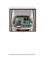
1
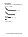
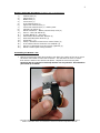
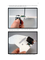
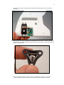
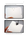
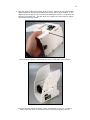
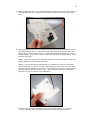
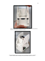
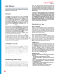
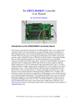
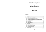
RoboticsConnection.com
Assembly Manual
©2004-2005 Summerour Robotics Corporation – Botster™ Assembly Manual Version 1.4 – 05/15/2005.
Botster™ and Botster Brand™ are Trademarks of Summerour Robotics Corporation 2004-2005.
2
BEFORE YOU BEGIN
ASSEMBLING BOTSTER™…
IMPORTANT - PLEASE DO NOT USE ANY POWER TOOLS TO ASSEMBLE YOUR KIT. Use
only the required held phillips head screwdriver and hex wrenches.
NOTICE: We will not warranty any parts with stripped out holes, for which you have stripped
out using power tools.
The plastic material that our kits are manufactured out of has been tested to ensure that it
provides enough strength to withstand typical hand torquing of screws, and provide sufficient
wear characteristics for typical insertions and removals of screws.
Once the screw is “seated” on the plastic, apply a 1/8 turn (45 degrees of clockwise rotation)
of the screwdriver and STOP. DO NOT apply any more torque. We define “seated” as when
the bottom of the screw head comes in contact with the plastic.
Also, our kits are designed so as to not require the user to have to frequently remove screws
to get to other parts of the kit. So, once the kit is together, leaving it together will help
prolong the life of it.
We believe you will be very pleased with the solidity and rigidity of the assembled kit.
©2004-2005 Summerour Robotics Corporation – Botster™ Assembly Manual Version 1.4 – 05/15/2005.
Botster™ and Botster Brand™ are Trademarks of Summerour Robotics Corporation 2004-2005.
3
Pre-Construction Information:
Before assembling your Botster™ kit, get familiar with the material below so you will
better understand the nomenclature used in this guide.
Botster™ Screw Types and Sizes:
Button Head Cap Screw (BHCS):
6-32 x 1/2” (For wheel encoder modules and rear caster)
Flat Head Cap Screw (FHCS):
6-32 x 1/2” (Chassis, servos)
6-32 x ¼” (Colored trim pieces)
6-32 Nut:
(wheel encoder modules, and caster)
TOOLS:
You will need the following common hand tools to fully assemble your Botster™ kit.
• Combination hex wrench set (Specifically 5/64” & 7/64” size wrenches)
• Phillips head screwdriver
• Razor Blade, utility knife, or xacto knife
©2004-2005 Summerour Robotics Corporation – Botster™ Assembly Manual Version 1.4 – 05/15/2005.
Botster™ and Botster Brand™ are Trademarks of Summerour Robotics Corporation 2004-2005.
4
Botster™ Robot Kit Part Names (Quantity each in parentheses):
1.)
2.)
3.)
4.)
5.)
6.)
7.)
8.)
9.)
10.)
11.)
12.)
13.)
14.)
15.)
16.)
17.)
18.)
Chassis Sides (2)
Upper Deck (1)
Middle Deck (1)
Lower Deck (1)
Front Vertical Deck (1)
Upper Rear Vertical Deck (1)
Lower Rear Vertical Deck (1) - Battery Door
Colored Trim Pieces (4)
Wheel assemblies – Wheels, Encoder disk, Hubs (2)
Servos – Hitec HS-322HD (2)
Traction Bands (4) - two extra
Hamamatsu Wheel Encoder Modules (2)
Rear Steel Ball Caster & Mount (1)
Screw Pack – (1)
Sharp™ GP2D120 infrared sensor mount blocks (2)
Front infrared sensor aluminum hex standoffs (2)
Generic or CMUcam2 Turret and servos (Optional) (1)
Wheel encoder spacer tubing material
Assembling the Botster™ kit:
1.
Start by trimming the small ribs protruding just above the surface of the servo mount
tab with a razor blade or xacto knife as shown. This will allow the servo to mount
flush with the inside of the chassis side plates. Repeat for both mounting tabs.
Caution!!! Be very careful on this step and do not cut yourself! This should be
performed by an adult!
©2004-2005 Summerour Robotics Corporation – Botster™ Assembly Manual Version 1.4 – 05/15/2005.
Botster™ and Botster Brand™ are Trademarks of Summerour Robotics Corporation 2004-2005.
5
Here’s what the mounting tab should look like when you’re finished trimming the tab
flush.
2.
Start threading in four of the supplied 6-32 x 1/2” flat head cap screws as shown into
each of the chassis sides. Thread them in until about 1/8” of an inch is sticking out of
the other side of the chassis side plate.
©2004-2005 Summerour Robotics Corporation – Botster™ Assembly Manual Version 1.4 – 05/15/2005.
Botster™ and Botster Brand™ are Trademarks of Summerour Robotics Corporation 2004-2005.
6
3.
To install the servos in the chassis sides, continue threading each of the four 6-32 flat
head cap screws, up through the servo flange holes, into four 6-32 nuts as shown.
Make sure you have all of the bolts threaded into the nuts before tightening them
down, othewise, it’ll be hard to thread them all in. Also, make sure the servo wire is
pointing toward the bottom of the Botster™, and that the servo mounting flange is
flush with the bottom of the chassis side.
Here’s what the chassis sides should look like when this step is completed.
©2004-2005 Summerour Robotics Corporation – Botster™ Assembly Manual Version 1.4 – 05/15/2005.
Botster™ and Botster Brand™ are Trademarks of Summerour Robotics Corporation 2004-2005.
7
4.
Next, cut the wheel encoder spacers using the include wheel encoder spacer tubing
material. Using a razor blade or xacto knife, slice the tubing into four 1/16” sections
as shown below.
Here’s what the four washers will look like when you’ve finished cutting them.
Enough material was included in the kit that if you mess up a couple, you’ll still have
plenty of material to cut more. NOTE: Do not use metal washers for spacers since
they could short the electric circuit on the wheel encoder module!
©2004-2005 Summerour Robotics Corporation – Botster™ Assembly Manual Version 1.4 – 05/15/2005.
Botster™ and Botster Brand™ are Trademarks of Summerour Robotics Corporation 2004-2005.
8
5.
Bolt each wheel encoder to the chassis sides using two 6-32 x 1/2” button head cap
screws and the wheel encoder spacers you just cut.
Use two 6-32 nuts to captivate the encoder module button head cap screws
(both chassis sides) as shown.
©2004-2005 Summerour Robotics Corporation – Botster™ Assembly Manual Version 1.4 – 05/15/2005.
Botster™ and Botster Brand™ are Trademarks of Summerour Robotics Corporation 2004-2005.
9
Here’s what the wheel encoders and chassis sides should look like at this point of
assembly.
6.
Bolt the steel ball caster assembly to the bottom deck as shown. Start by placing the
steel ball into the plastic housing, and the place the steel rollers on top of the ball (be
careful, they’ll fall out!)
©2004-2005 Summerour Robotics Corporation – Botster™ Assembly Manual Version 1.4 – 05/15/2005.
Botster™ and Botster Brand™ are Trademarks of Summerour Robotics Corporation 2004-2005.
10
Next, place the bottom deck onto the ball housing (the deck has three slots that the
tabs on the ball housing will fit down into as shown.
Use three 6-32 x 1/2” button head cap screws to bolt the housing to the bottom deck
as shown.
©2004-2005 Summerour Robotics Corporation – Botster™ Assembly Manual Version 1.4 – 05/15/2005.
Botster™ and Botster Brand™ are Trademarks of Summerour Robotics Corporation 2004-2005.
11
7.
Captivate the caster bolts with three 6-32 nuts as shown.
8.
Start threading six 6-32 x 1/2” flat head cap screws into each of countersunk holes
along the bottom of the bottom deck (don’t worry about the two in the middle yet).
©2004-2005 Summerour Robotics Corporation – Botster™ Assembly Manual Version 1.4 – 05/15/2005.
Botster™ and Botster Brand™ are Trademarks of Summerour Robotics Corporation 2004-2005.
12
9.
Bolt each chassis side to the bottom deck as shown. Make sure you hold the sides
tightly against the bottom when starting the screws with no gaps showing. If you
happen to have a gap once you’ve started threading the screws in, simply back the
screws out and start over. This will allow you to apply very little torque to tighten
them down when fully seated.
Here’s what the Botster™ should look like once you bolt sides to the bottom.
©2004-2005 Summerour Robotics Corporation – Botster™ Assembly Manual Version 1.4 – 05/15/2005.
Botster™ and Botster Brand™ are Trademarks of Summerour Robotics Corporation 2004-2005.
13
10. Start threading two 6-32 x 1/2” flat head cap srews into the two holes in the middle of
each side plate as show until the end of the screw is flush w/ the inside of the side
plate.
11. Start threading in two 6-32 x 1/2” flat head caps screws into the countersunk holes on
the middle deck as shown. These are the two holes pictured in the top right of the
picture below with the screws in them. NOTE: Some middle decks may have extra
holes as shown. In this case, simply use the holes closest to the angled notch. Ignore
the other two holes.
NOTE 1: If you’re not going to be using the Sharp™ infrared sensor blocks, then don’t
bother threading in the flat head cap screws.
NOTE 2: If you purchased the optional Generic or CMUcam2 Turret for the Botster,
then thread in the two 6-32 x 1/2” flat head cap screws used to bolt the turret servo
pan base into the middle deck as shown. These are the two holes in the bottom left of
the picture below with the screws in them. Also, follow the next steps. Otherwise,
skip down to step 14 to bolt in the middle deck.
©2004-2005 Summerour Robotics Corporation – Botster™ Assembly Manual Version 1.4 – 05/15/2005.
Botster™ and Botster Brand™ are Trademarks of Summerour Robotics Corporation 2004-2005.
14
12. Bolt the two Sharp™ IR sensors to the sensor mounting blocks as shown with the
included 6-32 x 1/4” socket head cap screws as shown.
13. Bolt both on the Sharp™ infrared sensor blocks and sensors onto the top of the middle
deck as shown using a 6-32 x 1/2” flat head cap screw (Unless you’re not going to be
using these, in which case, save them, and skip this step).
©2004-2005 Summerour Robotics Corporation – Botster™ Assembly Manual Version 1.4 – 05/15/2005.
Botster™ and Botster Brand™ are Trademarks of Summerour Robotics Corporation 2004-2005.
15
14.
Here’s what the top of middle deck should look like at this point.
NOTE: The sensor blocks should be pointed at roughly 45 degrees off of the
centerline of the middle deck.
15.
Now’s the time to plug in the Sharp IR sensor cables! If you do not do so
before installing the turret (if you own one), you won’t be able to,
unless you remove the turret. Also, go ahead and insert the cable into the
front Sharp IR sensor, before bolting it into the front deck (below). Otherwise
you’ll face a similar situation.
©2004-2005 Summerour Robotics Corporation – Botster™ Assembly Manual Version 1.4 – 05/15/2005.
Botster™ and Botster Brand™ are Trademarks of Summerour Robotics Corporation 2004-2005.
16
16.
(Optional)
If you ordered a Generic or CMUcam2 turret, note the position of the adjustable
turret servo horn on the tilt servo, remove it, and modify it as shown using a
razor blade or xacto knife. This will provide clearance with the rear vertical
deck when the Botster is fully assembled. Make sure you cut the horn as shown
below with the serrated side down. You’ll only need to trim the one side
shown.
Now bolt the servo horn back onto the servo in the same position from which
you removed it.
17.
Bolt the Generic or CMUcam2 turret onto the top of the middle deck as shown
with the previously threaded in 6-32 x 1/2” flat head cap screws.
©2004-2005 Summerour Robotics Corporation – Botster™ Assembly Manual Version 1.4 – 05/15/2005.
Botster™ and Botster Brand™ are Trademarks of Summerour Robotics Corporation 2004-2005.
17
You can wrap the excess tilt servo wire around the back of the
turret a couple of times to keep it out of the way. If you’re using the
CMUcam2 turret version, then you can plug the servo connector into the
second servo port, which is the one used to control tilt. Now you can simply
send commands serially to the CMUcam2 to tilt the servo in the desired
direction. Please follow the CMUCam2 user manual for instructions on how to
connect the CMUcam2 to your controller.
NOTE: The servo will turn farther than the turret can tilt, so you will have to
limit it’s movement via software. Go to our “Documents and Downloads” web
page for examples on how to implement this for the BasicX and OOPic-R
microcontrollers. If the servo makes a humming noise once it moves the
turret plate to it’s extent in either direction, then it’s moving to far, and should
be backed off a little.
Also insert two 6-32 x 1/2” flat head cap screws into the two front countersunk
holes as shown below. These will be used to bolt in the front vertical deck.
Here’s what the middle deck with turret assembly should look like at this point.
©2004-2005 Summerour Robotics Corporation – Botster™ Assembly Manual Version 1.4 – 05/15/2005.
Botster™ and Botster Brand™ are Trademarks of Summerour Robotics Corporation 2004-2005.
18
18.
19.)
Bolt the middle deck into the Botster™ as shown.
If you ordered the Sharp™ GP2D infrared sensor pack, install the two threaded
hex standoffs included in that kit into each of the two holes in front vertical platter
as shown.
©2004-2005 Summerour Robotics Corporation – Botster™ Assembly Manual Version 1.4 – 05/15/2005.
Botster™ and Botster Brand™ are Trademarks of Summerour Robotics Corporation 2004-2005.
19
20.)
Now bolt in one of your Sharp™ GP2D infrared sensors using the 6-32 x 1/4”
socket head cap screws included in the infrared sensor kit as shown. Once you
get it bolted in, it’s a good idea to connect the sensor wire while you have
easy access to the connector.
21.)
Bolt in the front vertical deck as shown using four 6-32 x 1/2” flat head cap
screws (2 in bottom deck, 2 in middle deck).
©2004-2005 Summerour Robotics Corporation – Botster™ Assembly Manual Version 1.4 – 05/15/2005.
Botster™ and Botster Brand™ are Trademarks of Summerour Robotics Corporation 2004-2005.
20
Here’s what the Botster™ should look like at this point (NOTE: You may have the
Generic or CMUcam2 turret bolted in as well).
©2004-2005 Summerour Robotics Corporation – Botster™ Assembly Manual Version 1.4 – 05/15/2005.
Botster™ and Botster Brand™ are Trademarks of Summerour Robotics Corporation 2004-2005.
21
22.)
Bolt on the top and bottom trim pieces using seven 6-32 x 1/4” flat head cap
screws per side as shown. NOTE: Do not insert them into the holes shown below
which do not have them. We will use 6-32 x 1/2” flat head cap screws in the
empty holes in the next step.
23.)
Bolt on the upper deck using four 6-32 x 1/2” flat head cap screws thru each side
plate as shown below.
©2004-2005 Summerour Robotics Corporation – Botster™ Assembly Manual Version 1.4 – 05/15/2005.
Botster™ and Botster Brand™ are Trademarks of Summerour Robotics Corporation 2004-2005.
22
24.)
Bolt the upper rear vertical deck onto the back of the Botster’s chassis as shown
using four 6-32 x 1/2” flat head cap screws. The upper rear vertial deck is a
perfect place to mount our plug-n-play breadboard for the BX-24 or OOPic-R.
©2004-2005 Summerour Robotics Corporation – Botster™ Assembly Manual Version 1.4 – 05/15/2005.
Botster™ and Botster Brand™ are Trademarks of Summerour Robotics Corporation 2004-2005.
23
25.)
Thread in one 6-32 x 1/2” flat head cap screw per side in the countersunk hole
shown, and bolt in the lower rear vertical deck (battery door). NOTE: DO NOT
tighten these screws up to allow the rear vertical deck to rotate up and down for
access to Botster’s™ inner cavities.
©2004-2005 Summerour Robotics Corporation – Botster™ Assembly Manual Version 1.4 – 05/15/2005.
Botster™ and Botster Brand™ are Trademarks of Summerour Robotics Corporation 2004-2005.
24
26.)
Thread in two 6-32 x 1/2” flat head cap screws into the two countersunk holes in
the top of the lower rear vertical deck and bolt it into the upper deck as shown.
You an simply takes these out to insert/remove batteries as needed.
27.)
Stretch the included traction bands around the Botster wheels. You’ll have to
stretch and tug to get the band centered perfectly. Once it’s centered, it should
easily stay in that position, even while driving.
28.)
Bolt on the Botster’s™ wheels using the black servo screws in the ends of the
splined servo shafts.
©2004-2005 Summerour Robotics Corporation – Botster™ Assembly Manual Version 1.4 – 05/15/2005.
Botster™ and Botster Brand™ are Trademarks of Summerour Robotics Corporation 2004-2005.
25
29.)
That’s it! You’re now ready to bolt on your controllers and other sensors and
make Botster perform some cool tasks! Good luck! Please let us know if you
encountered any issues which weren’t explained clearly in this manual so we can
improve it for our future customers. Thank you!
OOPic-R and BasicX-24 installation (Optional):
Follow these steps to install an OOPic-R or BasicX-24 board onto the top deck of the
Botster with the included mounting kit (only included w/ Botster + controller combo).
1.) Drill out the four mounting holes in either the OOPic-R or the BasicX-24
microcontroller (depending on which one you have) using a #28 drill. This drill is
about 0.140” in diameter. Be SURE to hold the controller firmly and flat when drilling
so as to not lose control of it! THIS STEP SHOULD BE PERFORMED BY AN ADULT
of 18 years or older!!
©2004-2005 Summerour Robotics Corporation – Botster™ Assembly Manual Version 1.4 – 05/15/2005.
Botster™ and Botster Brand™ are Trademarks of Summerour Robotics Corporation 2004-2005.
26
2.) Install the ½” x 6-32 hex standoffs into the top of the upper deck by inserting the
threaded end into the holes in the upper deck, which correspond to the controller
being mounted. NOTE: The four outer most holes correspond to the OOPic-R and the
four innermost holes correspond to the BasicX-24 controller. Thread them in until
they bottom out as shown below:
3.) Bolt the OOPic-R or BasicX-24 onto the standoffs using the four included 6-32 x ¼
socket head cap screws as shown.
©2004-2005 Summerour Robotics Corporation – Botster™ Assembly Manual Version 1.4 – 05/15/2005.
Botster™ and Botster Brand™ are Trademarks of Summerour Robotics Corporation 2004-2005.
27
Here’s what it should look like when you’ve finished mounting your controller.
That’s it!
©2004-2005 Summerour Robotics Corporation – Botster™ Assembly Manual Version 1.4 – 05/15/2005.
Botster™ and Botster Brand™ are Trademarks of Summerour Robotics Corporation 2004-2005.