1
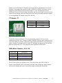
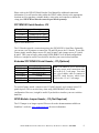
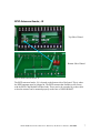
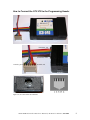
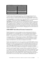
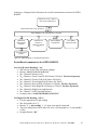
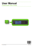
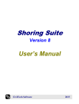
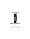
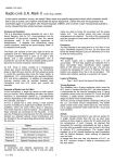
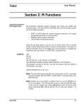
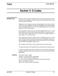
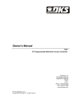
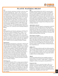
The OPEN-ROBOT Controller
User Manual
By Abe Howell’s Robotics
Introduction to the OPEN-ROBOT Controller Board
This board was specifically designed for the OPEN-ROBOT and is a very unique robot
controller in that it not only incorporates a suitable H-Bridge chip for controlling two
GM-8 gearhead motors, but it also has dedicated pins and a connector for utilizing two
WW-02 Wheel Encoders from for Proportional Integral Derivative (PID) velocity and
position control of the GM-8 motors. While this in and of itself is a tremendous benefit,
there are other significant features such as direct integration of a low-cost Radio
Frequency Identification (RFID) chip module, which gives OPEN-ROBOT the ability to
read and write to in-range passive RFID Tags. There are a total of eight (8) analog to
digital capable pins, two (2) are dedicated to light sensing photocells, one (1) is used to
monitor the board’s supply voltage and the remaining five (5) are available to be used as
needed by the user. A user-friendly firmware and boot-loader is programmed into the
PIC18F4520. The boot-loader allows for wireless uploading of new firmware versions,
but also of user created code that is developed using a suitable CCS C compiler. This
board also supports development, programming, and debugging of user created programs
via a dedicated programming header. This programming header can be used to load and
debug new programs or new firmware upgrades and has been tested with an In-Circuit
Programmer/Debugger (ICD) from CCS Inc. The OPEN-ROBOT controller board has
been developed and evolved over several years and we hope that you find this to be a
useful tool in your quest to build a great robot. Please send all questions and comments to
[email protected]
OPEN-ROBOT Controller Board User Manual by Abe Howell’s Robotics, 8/22/2008
1
Board Connectors
Extended PIC
Serial Header, J11
Programming
Header, J2
Board Power, J1
Extra I/O, J3
Ground
Header, J5
WW-02 Encoders
Header, J4
PIC Serial
Header, J12
+5 Volt Header, J6
Figure#1, Board Connectors
Left GM-8
Header, J9
(5) Analog to Digital (A/D) Pins, J14 & J15
Right GM-8
Header, J10
I2C Header, J7
Figure#1 points out all the board connectors. The upcoming sections will explain each of
these connections in more detail.
OPEN-ROBOT Controller Board User Manual by Abe Howell’s Robotics, 8/22/2008
2
Board Power & Programming Header, J1 & J2
Header Pin#
J1 Pin#1
J1 Pin#2
J2 Pin#1
J2 Pin#2
J2 Pin#3
J2 Pin#4
J2 Pin#5
J2 Pin#6
Description
Vin (6 to10 volts)
Ground
Ground
+5 volts
PIC18F4520 MCLR
PIC18F4520 Pin B7
PIC18F4520 Pin B6
PIC18F4520 Pin B3
Figure#2, Power & Programming Headers (J14& J2)
The board can be powered in the range of 6-10 volts. We recommend using (6)-AA
batteries. Power is applied at the J1 header and pin#1 is +Vin and pin#2 is ground. A
polarized header is used to help prevent plugging the board power connector in
backwards. Reversing the polarity of the J1 connector will more than likely result in
damage to the one or both of the +5volt regulators at U1 and U2 and possibly other
components as well, so please be careful when applying power to the board. The
programming header allows the PIC18F4520 to be programmed and debugged with an
In-Circuit Programmer/Debugger (ICD) from CCS Inc. J2 pin#1 connects to ground on
the board, pin#2 to +5 volts on the board, pin#3 to MCLR on the PIC18F4520, pin#4 to
B7 on the PIC18F4520, pin#5 to B6 on the PIC18F4520, and pin#6 to B3 on the
PIC18F4520. You will need to fabricate a cable to connect to the appropriate pins on the
ICD (explained later on in detail). If you have a PIC Programmer you can also fabricate
a cable to connect to J2 as well.
A/D#5
A/D#4
A/D#3
A/D#2
A/D#1
Analog to Digital (A/D) Headers, J14 & J15
Input Signal (Row#1)
+5 Volts (Row#2)
Ground (Row#3)
Vin (Row#4)
Header#’s
Figure#3, A/D Headers (J14 & J15)
The J14 & J15 headers provide connection points to the PIC18F4520’s analog to digital
(A/D) capable pins. Header#1 is for A/D Sensor#1, header#2 is for A/D Sensor#2,
OPEN-ROBOT Controller Board User Manual by Abe Howell’s Robotics, 8/22/2008
3
header#3 is for A/D Sensor#3, header#4 is for A/D Sensor#4, and header#5 is for A/D
Sensor#5. The headers run vertically so that a GP2D120 or GP2D12 IR Sensor can be
plugged in. Each header provides an input signal, +5 volts, and ground pin for the
connected IR Sensor. Be sure to plug your sensors into the correct pins, since an incorrect
connection can damage either the sensor and/or the board. Each input signal pin connects
to a corresponding A/D channel on the PIC18F4520.
I2C Header, J7
Header Pin#
J7 Pin#1
J7 Pin#2
J7 Pin#3
Description
I2C SDA
I2C SDL
Ground
Figure#4, I2C Header, J7
J7 provides access to the board’s I2C pins and ground, so that I2C devices can be
connected here. Pin#1 on J7 connects to SDA on the PIC18F4520, pin#2 connects to SCL
on the PIC18F4520, and pin#3 connects to ground on the PIC18F4520. You will need to
solder a suitable 3-position header to use the I2C and make the appropriate PIC18F4520
firmware changes since I2C is not supported in the supplied serial firmware.
GM-8 Motor Headers, J9 & J10
Header Pin#
J9 Pin#1
J9 Pin#2
J10 Pin#1
J10 Pin#2
Description
Left Motor Top Lead
Left Motor Bottom Lead
Right Motor Bottom Lead
Right Motor Top Lead
Figure#5a, GM-8 Headers, J9 & J10
The left GM-8 gear motor connects to the J9 header and the right GM-8 to the J10
header. Connecting the GM-8’s incorrectly will only result in improper wheel rotation
and encoder readings and can be corrected by simply switching the motor leads.
OPEN-ROBOT Controller Board User Manual by Abe Howell’s Robotics, 8/22/2008
4
Figure#5b, GM-8 Noise Suppression Capacitors
Three 100pf ceramic capacitors must be soldered to each GM8 motor when WW02
Wheel Encoders are added otherwise motor noise will negatively affect the WW02
Wheel Encoder readings.
Extra I/O & WW-02 Wheel Encoders Header, J3 & J4
Figure#6, Extra I/O & Wheel Encoders Header, J3 & J4
Header Pin#
J3 Pin#1
J3 Pin#2
J3 Pin#3
J3 Pin#4
J3 Pin#5
J3 Pin#6
J3 Pin#7
J3 Pin#8
J4 Pin#1
J4 Pin#2
J4 Pin#3
J4 Pin#4
J4 Pin#5
J4 Pin#6
J4 Pin#7
J4 Pin#8
Description
PIC18F4520 Pin C5
PIC18F4520 Pin B7
PIC18F4520 Pin B6
PIC18F4520 Pin B5
PIC18F4520 Pin B4
PIC18F4520 Pin B3
PIC18F4520 Pin B2
PIC18F4520 Pin B1
Left WW-02 Clock Line (Violet wire)
Right WW-02 Clock Line (Violet wire)
Left WW-02 Direction Line (Orange wire)
Right WW-02 Direction Line (Orange wire)
Left WW-02 Ground (Black wire)
Right WW-02 Ground (Black wire)
Left WW-02 Vcc (Red wire)
Right WW-02 Vcc (Red wire)
OPEN-ROBOT Controller Board User Manual by Abe Howell’s Robotics, 8/22/2008
5
Please refer to the WW-02 Wheel Encoder User Manual for additional connection
information. You will need to either solder the WW02 cables directly to the appropriate
locations on J4 or purchase a suitable header, crimp pins, and connector to house the
crimp pins. WW02 Wheel Encoders must be purchased separately.
PIC18F4520 Serial Headers, J12
Header Pin#
J12 Pin#1
J12 Pin#2
J12 Pin#3
J12 Pin#4
Description
Connects to J11, pin2
Connects to J11, pin3
PIC18F4520 Serial RX
PIC18F4520 Serial TX
Figure#7, Serial Headers, J12
The J12 headers provide a connection point to the PIC18F4520’s Serial Port. Optionally,
you can use a set of jumpers to connect the TX and RX pins to the J11 header. To use this
feature simply attach a jumper across J12 pin#3 & pin#1 and a jumper across J12 pin#4
& pin#2. This is not necessary when using OPEN-ROBOT in its default configuration.
However, it might be useful if you decide to interface your own wireless hardware.
Extended PIC18F4520 Serial Header, J11 (Optional)
Header Pin#
J11 Pin#1
J11 Pin#2
J11 Pin#3
J11 Pin#4
J11 Pin#5
J11 Pin#6
Description
Pin Not Used
PIC18F4520 TX
PIC18F4520 RX
Ground
+5 volts
Pin Not Used
Note: This Board is a TTL device and
can only accept serial connections that
are in the 0 to 5 volt range. You must
use a level shifter cable to connect to
non-TTL serial devices, which have
levels in the –15 to 15 volt range.
Figure#8, Serial Header, J11
To use this feature, attach a jumper across J12 pin#3 & pin#1 and a jumper across J12
pin#4 & pin#2. This is not necessary when using OPEN-ROBOT in its default
configuration. However, it might be useful if you decide to interface your own wireless
hardware.
RFID Module Jumper Header, J13 (Not Required)
The J13 Jumper is no longer required. Please refer to the documentation available on
SonMicro’s web site: www.sonmicrom.com for more information.
OPEN-ROBOT Controller Board User Manual by Abe Howell’s Robotics, 8/22/2008
6
RFID Antennae Header, J8
Top Side of Board
Bottom Side of Board
Figure#9, RFID Antennae Header, J8
The RFID antennae header, J8, is located on the bottom side of the board. This is where
the RFID antennae must be plugged in. The RFID antenna that SonMicro sells for use
with the RFID Chip Module has short leads. These need to be extended by a short cable
so that the antenna can be mounted properly on the base of OPEN-ROBOT.
OPEN-ROBOT Controller Board User Manual by Abe Howell’s Robotics, 8/22/2008
7
How to Connect the CCS ICD to the Programming Header
ICD Pin#1, red
ICD Pin#6, violet
J2 Pin#1, green
J2 Pin#6, red
Figure#10, CCS ICD Cable & Connectors
OPEN-ROBOT Controller Board User Manual by Abe Howell’s Robotics, 8/22/2008
8
CCS ICD Connector to Program Connector
ICD Pin#
J2 Pin#
Pin#1 (Red Wire)
Pin#6 (Red Wire)
Pin#2 (Orange Wire)
Pin#5 (Orange Wire)
Pin#3 (Yellow Wire)
Pin#4 (Yellow Wire)
Pin#4 (Green Wire)
Pin#1 (Green Wire)
Pin5 (Blue Wire)
Pin#2 (Blue Wire)
Pin#6 (Violet Wire)
Pin#3 (Violet Wire)
Figure#11, ICD to Program Header, J2, Table
To build the above ICD programming cable you will need approximately 6-8” of 6conductor multicolor 28-gauge flat ribbon cable and a 6-pin RJ25 modular connector.
The 6-pin connector can be purchased from Radio Shack, part#279-421. The flat ribbon
cable (part#112547) can be purchased from Jameco Electronics. You will also need one
6-position 0.1” non-polarized connector (part#103211) and (6) crimp pins
(part#100756) from Jameco Electronics. It is recommended that you use the appropriate
crimp tools, but you can sometimes get away with using a pair of regular or needle-nose
pliers. Updating firmware or loading your own custom program can be performed using
the MatchPort b/g module and this does not require the use of an In-Circuit Programmer
since the PIC18F4520 has been pre-programmed with a boot-loader. Using the In-Circuit
Programmer/Debugger allows for true hardware debugging and can be an invaluable tool
when developing new code.
OPEN-ROBOT Serial-Based Firmware Command Set
The 802.11b/g protocol is used to maintain a wireless communication link between
OPEN-ROBOT and a corresponding 802.11b/g wireless equipped laptop, desktop pc,
Pocket PC (PPC) or micro-controller. However, as an option you can wire OPENROBOT’s serial port directly to a suitable device, but this will require that you fabricate
any necessary cables. The default serial port settings for OPEN-ROBOT are as follows:
115,200BPS, 8-data bits, 1-stop bit and no parity. Once properly installed & setup the
user can communicate with OPEN-ROBOT and create their own high-level programs
using Visual Studio.Net® or any software development tool of choice.
Simple serial command packets are used to communicate with OPEN-ROBOT and these
packets will inevitably vary in size, since different commands require either more or less
information. An entire command packet must be constructed and sent by the high-level
controlling program. OPEN-ROBOT will receive this packet and determine the packet’s
nature. Once OPEN-ROBOT deciphers the enclosed packet command, it will begin
execution or return the requested data. All incoming move commands take priority over a
previously issued command. Finally, all packets must be terminated with a line return
(“\r”) character or else they will become part of the next incoming command upon receipt
of the next line return along with any other packets that were sent prior to the line return.
The line return character allows OPEN-ROBOT to determine the end of a command
packet and then parse out the appropriate data. A built-in watchdog timer will restart the
PIC18F4520 if it is not reset in time, which in turn eliminates OPEN-ROBOT from
OPEN-ROBOT Controller Board User Manual by Abe Howell’s Robotics, 8/22/2008
9
locking up. A diagram below illustrates the overall communication structure for OPENROBOT.
Master Device: PC, PDA or
other serial capable device
Bi-directional 802.11b/g connection
OPEN-ROBOT’s PIC18F4520 Micro-controller
Onboard HBridge Motor
Controller
Attached A/D
Sensors &
Additional Digital
I/O
Onboard RFID
Chip Module
Two WW02
Wheel Encoders
Two GM-8 Gear
Motors
Figure#12, OPEN-ROBOT’s Communication Structure
Serial-Based command set for OPEN-ROBOT.
Get All A/D Sensor Readings: “A\r”
• Will retrieve all the 8-bit A/D sensor readings.
• Returns “aX0,X1,X2,X3,X4,X5,X6,X7\r”
• X0 = Channel 0 (battery level).
• X1 = Channel 1 (Front Center IR A/D Sensor J14 Pin#1). Purchase Separately
• X2 = Channel 2 (Front Left IR A/D Sensor J14 Pin#2).
• X3 = Channel 3 (Front Right IR A/D Sensor J14 Pin#3).
• X4 = Channel 4 (Rear Left IR A/D Sensor J15 Pin#4). Purchase Separately
• X5 = Channel 5 (Rear Right IR A/D Sensor J15 Pin#5). Purchase Separately
• X6 = Channel 6 (Right Front Light Sensor).
• X7 = Channel 7 (Left Front Light Sensor).
• Example return: “a140,120,110,108,0,1,145,151\r”
Get Digital I/O Pin Reading: “LX0\r”
• Gets the appropriate I/O pin reading.
• X0 = Pin number (0 to 7).
• Returns “l” + “pin reading” + “\r” upon receiving the command.
• The pin reading value will be either a 1 or 0. A 1 corresponds to +5 volts and 0 is
0 volts.
• Example Return: “l0\r”
OPEN-ROBOT Controller Board User Manual by Abe Howell’s Robotics, 8/22/2008
10
Get Wheel Encoder Readings: “E\r”
• Retrieves the left and right encoder readings.
• Returns “e X0, X1\r”
• X0 = Left encoder reading.
• X1 = Right encoder reading.
• Example Return: “E100,99\r”
Get A/D Sensor and Light Reflex Levels: “F\r”
• Retrieves 8-bit A/D Sensor and Light Reflex Level.
• Returns “f X0, X1\r”
• X0 = A/D Reflex Level.
• X1 = Light Reflex Level.
• Example Return: “f60,200\r”
Get PID Gains: “GX0\r”
• Gets the current set of 8-bit PID gains for the velocity or position controller.
• X0 = For position send “P” and for velocity send “V”
• Returns “gpKp,Ki,Kd\r”
• Returns “gvKp,Ki,Kd\r”
• Example Return: “gp5,2,1\r”
• Default Position PID gains are Kp = 5, Ki = 2, and Kd = 1.
• Default Velocity PID gains are Kp = 5, Ki = 1, and Kd = 1.
Get PWM Motor Offsets: “@G\r”
• Gets the current left and right 8-bit PWM Motor Offsets. These values are used to
offset the motor PWMs. The PIC18F4520’s hardware PWM can be set from 0 to
255, but the GM-8 motors may not begin to spin until say 195. By setting the
PWM Offsets to 195 we ensure that the motors start moving when we send an
open-loop speed greater than zero. This also helps the robot to drive straighter
during open loop velocity control, but is equally important for proper PID
velocity and position control.
• Returns “@X0, X1\r”, where X0 is the left PWM Motor Offset and X1 is the right
PWM Motor Offset.
• Example Return: “@195,198\r”
Is Robot Sensor Reflex Triggered: “B\r”
• Checks to see if robot is blocked by a sensor reflex. Used in conjunction with “Set
sensory reflex”, and “Reset Agent Blockage” commands.
• Returns “bc\r” if clear and “bb\r” if blocked.
Is Move Complete: “D\r”
• Checks to see if the current move is complete.
• Returns “da\r” if move complete and “dn\r” if not.
• When using Position control you do not know how long a move will take so
simply check this periodically until the move is complete and then issue the next
OPEN-ROBOT Controller Board User Manual by Abe Howell’s Robotics, 8/22/2008
11
command. This way the high-level controlling program can perform other
calculations while the robot moves to the requested position
Reset Robot Sensor Reflex: “R\r”
• Resets the robot’s sensor reflex. Used in conjunction with “Set sensory reflex”
and “Is Robot Sensor Reflex Triggered” commands.
• Returns “r\r” upon receipt of the command.
Reset RFID Module: “X\r”
• Resets the RFID Module.
• Returns “x\r” upon receipt of the command.
RFID Tag Found: “z\r”
• Checks to see if a valid RFID tag has been found by “RFID Search for Tag”.
Used in conjunction with “RFID Search for Tag “ command, “Z\r”.
RFID Search for Tag: “Z\r”
• Continuously searches for an in-range tag.
• Halts robot when tag is located or Stop Robot, “H\r”, is issued.
• Used in conjunction with RFID Tag Found command, “z\r”.
RFID Tag Read: “T\r”
• Attempts to read an in range RFID tag. If no tag in range or error, returns “tn\r”.
• Returns “t” + “four hex data bytes in ASCII” + “\r” upon receiving the
command.
• Example Return: “tabcd\r”, when the four bytes of tag data is converted from
ASCII characters to hexadecimal we get the following: “t61626364\r”.
RFID Write Tag: “WX0,X1,X2,X3\r”
• Writes four ASCII bytes to an in range tag. Only way to guarantee a successful
write is to read the tag afterwards and check the data.
• X0 = Byte#0.
• X1 = Byte#1
• X2 = Byte#2
• X3 = Byte#3
• Returns “wa\r” upon receiving and acknowledging the command.
• Suppose we want to write “abcd” to the tag. We would send the following:
“Wabcd\r”. If we then read the tag we should get: “tabcd\r”.
Save All Parameters To PIC18F4520 Data EEPROM: “Y\r”
• Saves all parameters to the PIC18F4520 data EEPROM.
• Saves velocity gains (KP, KI, KD), position gains (KP, KI, KD), A/D Reflex
Level, Light Reflex Level.
• Returns “y\r” upon receipt of the command.
OPEN-ROBOT Controller Board User Manual by Abe Howell’s Robotics, 8/22/2008
12
Set A/D Sensor Reflex Level: “CX0\r”
• Sets A/D Sensor Reflex level for Sensory Reflexes.
• X0 = 8-bit A/D sensor level to use with Sensory Reflexes.
• Use “Save All Parameters To PIC18F4520 Data EEPROM” so that setting
persists.
• Returns “c\r” upon receipt of the command.
Set Light Sensor Reflex Level: “NX0\r”
• Sets Light Sensor Reflex level for Sensory Reflexes.
• X0 = 8-bit Light sensor level to use with Sensory Reflexes.
• Use “Save All Parameters To PIC18F4520 Data EEPROM” so that setting
persists.
• Returns “n\r” upon receipt of the command.
Set Sensory Reflexes: “IX0\r”
• Sets sensory reflexes to be active or inactive for each of the (8) A/D Channels. In
active mode the agent will immediately stop when any of the active A/D Channels
exceeds the value set by Set A/D Reflex Level or Set Light Reflex Level.
• X0 = An 8-bit value that sets the specified A/D channels to be active or inactive.
• Each of the (8)-A/D channels is represented by one of the 8-bits. The least
significant bit, bit 0, represents A/D channel#0 (battery level), bit 1 corresponds
to A/D channel#1 (Front Center IR, J14 Pin#1), … , bit 7 corresponds to the front
left light sensor. To turn off all the A/D channel reflexes we would need to send a
zero (0), which would correspond to the following 8-bit string: “00000000”. If we
only wanted to turn on the reflex for the Rear Right IR (A/D channel#5) we
would send a hexadecimal 20 for X0, which corresponds to the following binary
string: “00100000”. If we only wanted to turn on the reflex for the front right light
sensor we would send a hexadecimal 40 for X0, which corresponds to the
following binary string: “01000000”. Next you would have to convert the
hexadecimal value to a corresponding character to send out as serial data. All
Sensory Reflexes are turned off upon startup.
• Returns “i\r” upon receipt of the command.
Set Digital I/O Pin Low: “JX0\r”
• Sets the appropriate I/O pin low.
• X0 = Pin number (0 to 7).
• Returns “j\r” upon receiving the command.
Set Digital I/O Pin High: “KX0\r”
• Sets the appropriate I/O pin high.
• X0 = Pin number (0 to 7).
• Returns “k\r” upon receiving the command.
Set Position PID Controller Gains: “PX0X1\r”
• Sets the specified 8-bit Position PID gain.
OPEN-ROBOT Controller Board User Manual by Abe Howell’s Robotics, 8/22/2008
13
•
•
•
•
•
•
X0 = For KP send “P”, KI send “I” and KD send “D”.
X1 = 8-bit Gain Value.
Use “Save All Parameters To PIC18F4520 Data EEPROM” so that setting
persists.
Returns “p\r” upon receiving command.
Default Position PID gains are Kp = 5, Ki = 2, Kd = 1.
Changing the default values can degrade OPEN-ROBOT’s performance.
Set PWM Motor Offsets: “@X0X1\r”
• Sets the specified 8-bit PWM Motor Offset.
• X0 = “L” to set the left PWM Motor Offset or “R” to set the right PWM Motor
Offset.
• X1 = 8-bit PWM Motor Offset value to set.
• Use “Save All Parameters To PIC18F4520 Data EEPROM” so that this setting
change persists.
• Returns “@\r” upon receiving command.
• Default PWM Motor Offset value is 195.
• Example to set left PWM Offset to 199. “@L199\r”.
• Changing the default value can degrade OPEN-ROBOT’s performance.
• Read PWM Motor Offsets using the Get PWM Motor Offsets command, “@G\r”.
Set Velocity Controller PID Gains: “Q X0X1\r”
• Sets the specified 8-bit Velocity PID gain.
• X0 = For KP send “P”, KI send “I” and KD send “D”.
• X1 = 8-bit Gain Value.
• Use “Save All Parameters To PIC18F4520 Data EEPROM” so that setting
persists.
• Returns “q\r” upon receiving command.
• Default Velocity PID gains are Kp = 5, Ki = 1, Kd = 1.
• Changing the default values can degrade OPEN-ROBOT’s performance.
Set Position Closed Loop: “MP X0, X1\r”
• Sets the desired position in terms of wheel encoder ticks and uses PID position &
velocity control to complete the move. Use Is Move Complete to check for when
the move is done.
• X0 = Number of Left encoder ticks.
• X1 = Number of Right encoder ticks.
• Left & Right encoder ticks must be an integer in the range of –250 to 250.
• All incoming move commands will cancel a previously issued command.
• Returns “ma\r” upon receiving and acknowledging the command.
Set Velocity Closed Loop: “MV X0, X1\r”
• Sets the wheel velocities and performs PID velocity control.
• X0 = Left motor velocity.
• X1 = Right motor velocity.
OPEN-ROBOT Controller Board User Manual by Abe Howell’s Robotics, 8/22/2008
14
•
•
•
Left/Right motor velocity will be an integer in the range of –55 to 55 and have
units of tenths of an inch per second.
All incoming move commands will cancel a previously issued command.
Returns “ma\r” upon receiving and acknowledging the command.
Set Velocity Open Loop: “MO X0, X1\r”
• Sets the open loop velocity of each wheel.
• X0 = Left PWM motor speed.
• X1 = Right PWM motor speed.
• Left/Right PWM motor speed will be an integer in the range of –55 to 55.
• All incoming move commands will cancel a previously issued command.
• Returns “ma\r” upon receiving and acknowledging the command.
Stop Robot: “H\r”
• Immediately stops the GM-8 Motors, however, robot may coast before stopping.
• Returns “h\r” upon receiving the command.
Wander Mode: “U\r”
• Robot will wander with an open loop velocity of 25 and avoid obstacles based
upon currently set A/D Sensor Reflex Level and using the front left and front
right IR sensor.
• Behavior halts when Stop Robot command, “H\r”, is issued.
If you intend to use Visual Studio® to create high level control programs then you might
want to use our freely available C# class library, which encapsulate all the above-listed
commands for OPEN-ROBOT and allows you to quickly get started with writing some
useful code. Please refer to our web site for further information regarding this useful class
library.
Conclusion
We here at Abe Howell’s Robotics hope that you find the OPEN-ROBOT useful in your
various robotics projects, competitions and research. We intend to continue to develop
additional user material for OPEN-ROBOT so please be patient and check the web site
frequently. As always if you have questions or comments please email them to
[email protected] and have a great robotics experience!
OPEN-ROBOT Controller Board User Manual by Abe Howell’s Robotics, 8/22/2008
15