1
Social Robotics Platform Final Report Spring Semester 2015 - Full Report - Prepared by: Tessa Alford Adam Kattnig Meng Koh Josh Krokowski Melissa Wirtz Prepared to fulfill the requirements for ECE 402 Department of Electrical and Computer Engineering Colorado State University Fort Collins, Colorado 80523 Project Advisor: Dr. Tony Maciejewski Approved by: Dr. Tony Maciejewski on May 3, 2015 Abstract The purpose of the project is to create a device that utilizes a system to move a toy and engage children with major developmental disabilities. The goal of the device is to teach concepts of control (understanding that their action affects their environment), while encouraging the development of motor skills and the ability to reach for items. The platform takes input from a capability switch and responds with a motion. For example, if a child presses a button, the toy on the platform will move while music plays in the background. In this way a child can develop an aptitude for certain actions that will be important for their future, and they can develop important cognitive understanding that they can control their environment. The platform is designed in response to some disadvantages of a previous tool that therapists have used. These disadvantages included the toy containing electronics that could be easily damaged, the inability to detect user input, and the inability to address a diverse population of children with different developmental disability levels and different affinities for different toys and motions. The platform is designed to maintain the functionality of the predecessor design whilst addressing these shortcomings. It is also designed to be engaging, provide feedback to the user, teach principles of control, contain all electronics necessary for movement so that the toy does not contain electronics, and use a mechanism that allows for toys to be easily interchanged. The platform addressing these objectives will make it a powerful tool to assist in the therapy of children with developmental delays. The process of making the device was extensive and consisted of the advanced development, iterative design, and integration of many subsystems. The platform was completed in April of 2015. It was completed with significant input from staff and therapists at Respite Care, Fort Collins. Also, therapists brought in children to play with the platform, who found the platform very engaging. The platform did very well operationally as it was tested for over 6 hours at the Senior Design Showcase. Also, the device worked functionally by satisfying the objectives of engagement and teaching developmental concepts to children with developmental disorders. -2- Table of Contents Abstract ........................................................................................................................................... 2 List of Figures ................................................................................................................................. 4 1. Introduction ................................................................................................................................. 5 1.1 Project Overview: The Problem............................................................................................ 5 1.2 Objectives Overview ............................................................................................................. 7 1.3 Project Constraints and Requirements Overview ................................................................. 7 1.3.1 Budget ................................................................................................................................ 8 1.4 Project Final Design Subsystem Interaction Overview ........................................................ 8 1.5 Collaboration and Partnership............................................................................................... 8 2 Analysis of the Predecessor Design ............................................................................................. 9 3 Design Process ........................................................................................................................... 10 3.1 Concept Exploration and Definition of Movement Subsystem (Fall Semester) ................. 10 3.1.1 Mechanical Movement................................................................................................. 10 3.1.2 Electrical Control of Motors ........................................................................................ 13 3.1.3 Microcontroller and Software ...................................................................................... 13 3.1.4 Toy Attachment ........................................................................................................... 14 3.2 First Semester Summary ..................................................................................................... 14 3.3 Advanced Development and Testing (Spring Semester) .................................................... 14 3.3.1 Component Testing and Development......................................................................... 14 3.3.2 Subsystem Testing and Development .......................................................................... 15 3.3.3 System Testing ............................................................................................................. 16 4 Final Design ............................................................................................................................... 17 4.1 Microcontroller Unit (MCU) and Software ........................................................................ 18 4.2 Clinician User Interface ...................................................................................................... 18 4.3 Patient Interaction ............................................................................................................... 18 4.4 Case and Platform. .............................................................................................................. 19 4.5 Movement ........................................................................................................................... 20 4.7 Power .................................................................................................................................. 21 4.8 Extra Hardware ................................................................................................................... 22 5. Design Process Decisions ........................................................................................................ 23 5.1 Iterative Design ................................................................................................................... 23 5.2 Entire Device Design Considerations ................................................................................. 23 5.3 Individual Subsystem Design Considerations .................................................................... 23 5.3.1 Microcontroller Unit (MCU) Software ........................................................................ 24 5.3.2 Clinician and User Interface Design Considerations ................................................... 24 5.3.3 Patient Interaction Design Considerations ................................................................... 24 5.3.4 Case and Platform Design Considerations ................................................................... 25 5.3.5 Movement System Design Considerations .................................................................. 25 5.3.6 Reward Design Considerations .................................................................................... 26 5.3.7 Power Design Considerations ...................................................................................... 26 5.3.8 Extra Hardware Design Considerations ....................................................................... 27 6 Future Work and Conclusions ................................................................................................... 27 6.1 Summary of Work Finished by April 30, 2015 .................................................................. 27 6.2 Future Improvements .......................................................................................................... 28 6.3 Future Plans Concerning Production .................................................................................. 28 -3- 6.4 Conclusions ......................................................................................................................... 28 References ..................................................................................................................................... 29 Bibliography ................................................................................................................................. 29 Appendix A: Abbreviations used in Report .................................................................................. 30 Appendix B: Bill of Materials....................................................................................................... 31 Appendix C: Project Timeline (Gantt Chart) ................................................................................ 35 Appendix D: Circuitry Design for Motor Driver .......................................................................... 36 Appendix F: Pinouts ..................................................................................................................... 40 Appendix G: Senior Design Showcase (E-Days) Poster .............................................................. 41 Appendix H: User Manual ............................................................................................................ 42 Acknowledgements ....................................................................................................................... 50 List of Figures Figure 1: Predecessor Design - 3PI Robot ...................................................................................... 5 Figure 2: Toy Enclosing 3PI Robot ................................................................................................ 6 Figure 3: Example of 1/8" Input Jack ............................................................................................. 7 Figure 4: Cavity where 3PI Robot is Placed ................................................................................... 9 Figure 5: Drawing of Envisioned Final Design ............................................................................ 10 Figure 6: Electro-Magnetic Grid System ...................................................................................... 10 Figure 7: Two-Arm Design ........................................................................................................... 11 Figure 8: Two-Axis Design .......................................................................................................... 11 Figure 9: Decision Matrix for 3 Designs ...................................................................................... 12 Figure 10: CAD Model of Initial Envisioned Design for Movement Subsystem......................... 12 Figure 11: Custom Circuit Board, Bottom and Top (left to right) ................................................ 13 Figure 12: Bottom of Puck (left) and Toy Mounted on Puck (Right) .......................................... 14 Figure 13: Final Platform Device – Front View Showing Inputs and Outputs ............................ 17 Figure 14: Bird's Eye View of Internals of Final Platform Design .............................................. 17 -4- 1. Introduction The purpose of the Social Robotics Platform project is to create an interactive system that enables children with developmental delays to develop motor skills, develop reach, and develop a sense of control on their surroundings. Children with developmental delays often require repetition of tasks in order to progress through developmental milestones. The Social Robotics Platform will allow children to repeat exercises that will help them progress through developmental milestones. This report will discuss further background information on the project, previous design shortcomings, the need for a robotic platform design, constraints on the design and other project requirements. This will serve as background information for the following sections and is the same information that can be found in the fall report of the Social Robotics Platform. This report will also briefly cover the concept exploration phase, the decisions made to define a concept, and the development of the concept. Next, this report will explain the final design of the project and potential future plans of the project. Section 1 expands on background material of the project. Section 2 contains an analysis of the predecessor design. Section 3 contains information on the design process and discusses some key methods used throughout the design of the platform. Section 4 describes the final design by subsystem. Section 5 discusses design decisions that were made in order to produce the final design and defends the components used in the final design. Finally, section 6 discusses the future work that can be done on the project and concludes the report. 1.1 Project Overview: The Problem Patients that have serious neuro-muscular disorders or developmental disorders within the age range of zero to five often do not understand that they can control their environments and/or need to learn and develop special motor skills and reach. Several solutions have previously been designed to help teach several key concepts by Assistive Technology Partners at Colorado University, Denver. The most recent piece that was developed is called the 3PI robot. The 3PI robot can move around on a surface by means of a set of wheels on the bottom of the robot. The 3PI robot was modified so that the electronic portion of the system was placed inside of the toy in a manner where if the toy was sitting upright, the wheels could engage the surface that it was sitting on. Therefore, a toy could be moved around using the 3PI system. Figure 1 is the robotic portion of the 3PI robot that allows the robot to move. Figure 1: Predecessor Design - 3PI Robot -5- Figure 2 shows an example of a toy that can be fitted with the 3PI robot. The robot would be placed inside the toy to allow the toy to be moved around. Figure 2: Toy Enclosing 3PI Robot The 3PI robot was to be driven by a clinician (called a ‘wizard’ in this scenario) to see what patterns of movements could elicit response from patients. Whenever response was seen by the wizard, he/she could make the robot do dynamic motions to help patients understand that their response caused a response from the toy. However, there were several key problems with this robot, which are listed below. ● The robot could be knocked over or fall off a surface, in which the internal electronics had the potential to be damaged. ● The robot had no sense of where it was. ● The robot relied on batteries. ● If a new toy was desired to use the 3PI movement system, a completely new robot had to be created; this would entail the movement system being taken out and placed into a new toy that had to be correctly fitted for the movement system. ● The robot had no means of detecting if the patient was doing anything; therefore, it could not respond to the patient. -6- 1.2 Objectives Overview There are several objectives that fall within the scope of this project. They are listed here. ● Create a device that contains electronics so that the toys do not contain electronics ● Create a two-dimensional movement system that can be controlled by a wizard or controlled by the patient, that could track the position of the toy ● Use a wall-powered design ● Create a system where the toy could be easily attached and changed out ● Engage the patient by detecting action and encouraging the action by responding to the child’s actions ● Develop a case that contains the movement system that is sturdy and child-friendly ● Develop a system to be appropriate across patients with diverse developmental progress ● Encourage the development of control, reach, and motor skills The overarching idea behind the creation of this device and the creation of previous devices is to engage children with major developmental issues, exercise some basic movements, and teach them that they can control their environments by reinforcing intentional action with reward. 1.3 Project Constraints and Requirements Overview Several constraints were given, but the project was left relatively open for creativity and design. The customer asking for the development of this system asked that the system would be portable, child-friendly, and use four 1/8” input jacks (shown in Figure 3). The reasoning for the use of these jacks is further explained in section 5.3. The initial constraints that were developed are listed below. ● ● ● ● ● ● ● Weigh under 20 pounds Platform size of 16” by 16” to 24” by 24” and stand no more than 3” in height Use four 1/8” jacks as connection input points Use a two-dimensional platform Have rounded edges (case) Easy toy detachment Platform can make toy do multiple actions (8-12) Figure 3: Example of 1/8" Input Jack -7- 1.3.1 Budget A budget totaling $1250 was able to be used. A $500 sum was allocated from the University of Colorado, Denver (UCD) to be used on this project. Also, internal funding of $750 was supplied by the Electrical and Computer Engineering (ECE) Department at Colorado State University (CSU). Initially, an estimated cost of goods was calculated to be about $650. Through the full development of the system, it is estimated that the total spent on this project was $980. Also, the bill of materials for the final device (as seen in the Appendix) put the cost of the device at $555. 1.4 Project Final Design Subsystem Interaction Overview The final design of this project will consist of several subsystems, which are listed below. ● Microcontroller Unit (MCU) Software: Controls the movement of the toy and processes all inputs and outputs ● Clinician User Interface: Allows the clinician to choose a mode of operation for the platform and interact with the platform ● Patient Interaction: Act as interface points where capability switches (such as buttons) can be connected ● Case and Platform: Acts as a portable surface for a toy to move and provide a friendly interface with holes cut out for inputs and outputs ● Movement System: Controls the position of a toy ● Reward (Sounds, Lights, Toy Movement): Gives feedback and encouragement to the patient ● Power: Controls voltage and current to devices and other subsystems ● Extra Hardware: Control information flow and interactions between different subsystems These subsystems will interact with one another. The patient will create an input using a capability switch, such as a button or some motion. The input will be processed by the MCU depending on the mode of operation the clinician has chosen. A movement will then be generated by the platform. To patients, the toy on the platform will respond to their actions. Also, lights and sounds will contribute to the patient’s feedback. These subsystems are controlled and monitored by the power system and the extra hardware in the design. The outworking of the interaction of these subsystems are further discussed in section 4. 1.5 Collaboration and Partnership This project was done in partnership with Assistive Technology Partners at Anschutz Medical Campus, University of Colorado, Denver. Through this partnership, the project has been realized and defined. Also, Respite Care, Fort Collins has kindly partnered with the team to give feedback on the platform system and provide insight on how the project could be improved. -8- 2 Analysis of the Predecessor Design As previously mentioned, the predecessor design was formed into a system called the 3PI robot. It gets its name from the robot maze solver robot that is in charge of the toy movement. This device was modified by researchers at the University of Colorado, Denver so that it could be controlled. Then, as previously mentioned, the robot could be placed inside of a toy. A cavity where the robot (Figure 1) could go is shown in Figure 4. Figure 4: Cavity where 3PI Robot is Placed This system is meant to engage a child by moving in patterns that would make a patient want to play with it. Once therapists, who were driving the 3PI robot toy, saw that children were interested, they would drive the robot to keep the child interested and interact with the child. In this way, motor skills were developed and lessons concerning control could be developed. However, as mentioned before, there were several key problems with this robot. The issues with this toy was that the electronics in the 3PI robot were inside of the toy, making it prone to damage and making it difficult to interchange toys; also, the toy could not autonomously respond to a patient’s actions or act differently depending on the developmental stage of the patient. This is because it lacked a means to detect input from the user. These problems were to be addressed in the Social Robotics Platform project. The platform device would contain all necessary hardware and electronics to move the toy on top of the platform. Also, the toy would be attached to the platform in a way that toys could easily be attached and removed to provide a modular attachment interface for a diverse number of toys. -9- 3 Design Process This section will discuss the design process of the device, beginning with a brief overview of work done in the previous semester. Figure 5 shows a drawing of how the final product was envisioned. As it can be seen, a toy sits on top of a platform and is moved by the inner workings of the platform. Also, illustrated in Figure 5 are inputs for the patient and the wizard. Figure 5: Drawing of Envisioned Final Design 3.1 Concept Exploration and Definition of Movement Subsystem (Fall Semester) Through the concept exploration phase, the biggest subsystem that had to be considered was the movement subsystem. This subsystem would need to fit inside of the platform casing. Therefore, it is not observable in Figure 5. The movement subsystem would control the position and velocity of a toy on the platform. This is at the heart of the device. 3.1.1 Mechanical Movement Several movement mechanisms and alternatives were brainstormed. One initial idea was to use a grid of electro-magnets on the platform. A simple way to move the toy would be to attach a magnet to the toy and then turn the electromagnets on the platform on and off in a manner similar to trains that use this technology. For example, moving the toy to the right would require the activation of electromagnets in the platform in a manner where the magnets to the right of the toy would turn on and the magnets under the toy would turn off. In this way, the toy would be moved to the right. The grid system would look like Figure 6 where each node represents a magnet. Figure 6: Electro-Magnetic Grid System -10- Another idea was to use a two-arm planar-rotation device to move the toy. Essentially, this would look very similar to the arm shown in Figure 7. The first pivot point would lie in the center of the device and be able to spin around the center. The second arm would be able to rotate also, allowing for complex motion. In this design, the toy would be connected magnetically. There would be a magnet under the platform attached to the end of Link 2 (Figure 7) and magnets attached to the toy, which would be on top of the platform. Figure 7: Two-Arm Design Lastly, we developed an idea to use a two-axis movement design, implementing rails and motors that would move the device in one direction and use rails and motors to move the device in the direction orthogonal to the other direction. This idea can be summarized in Figure 8. Figure 8: Two-Axis Design Each of these three initial ideas were compared under many criteria. Figure 8 contains a list of criteria in order of highest importance and using a basic rating system of an ‘S’ representing the anticipation that the design would be satisfactory in that category. Design 1 was the design using a grid of magnets, Design 2 was the design using a two-arm device, and Design 3 was the design using a 2-axis rail system. Figure 9 represents a summary of the discussion for these 3 designs. -11- Figure 9: Decision Matrix for 3 Designs Design 1 Design 2 Design 3 S S S Smooth Motion S S Dynamic Movement S S Potential Failure Cost S Easy to Modify S Durability S Reliability S S S S Location Feedback Noise S S Speed S Weight S TOTAL 5 S S 7 10 Once deciding on a generic design, the team developed a CAD model design of what could be created. This is shown in Figure 10. Figure 10: CAD Model of Initial Envisioned Design for Movement Subsystem -12- Several iterations of this design were created with minor adjustments; however, this design, for the most part, was kept even to the final design. Iterations included adjustments in the number of rails being used, the size of the center motor, the placement of the pulleys and motors, device weight, and the distance that the toy could move. Using the Pugh Method (Appendix E), iterations of designs with slight alterations were made so that a design was found that was superior to the design shown above in the CAD model (Figure 10). More detail of the iterations can be found in Section 5. 3.1.2 Electrical Control of Motors Also in the movement system, there needed to be some form of motor drivers. We had several options. The first was to use an H-bridge and drive the motors using transistors to supply the current. However, this proved to be difficult to implement with stepper motors. Another option was to use motor driver shields that were available for purchase. However, these could only drive 2 motors at a time without multiplexing. Finally, it was decided that a custom set of motor driver circuits would be created. This ended up being more economical and simpler to integrate into the device. Although it was a little more complex than using a shield and a pre-made library, it proved to be a very efficient way to drive the three motors necessary for X movement, Y movement, and rotation. Figure 11 shows both sides of the boards that were created and schematics can be seen in Appendix D. Figure 11: Custom Circuit Board, Bottom and Top (left to right) 3.1.3 Microcontroller and Software Another large component that required consideration was the microcontroller. Although it does more than control the motors, controlling the motors is one of its most important functions and was largely considered when choosing a microcontroller to use. Also, the team was already familiar with the Arduino. Because of the level of experience the team had and the resources available for the Arduino, there was a large affinity for this family of microcontrollers. Also, the Arduino Mega 2560 had enough pins (with diverse functions) that it made for a great candidate for the project. The pins needed were serial (I2C) pins, analog pins, digital IO pins (to drive inputs, outputs, and motors) and PWM (pulse width modulated) pins. Therefore, because of its usability, amount of resources available, and meeting the desired specs of a microcontroller, it was decided that an Arduino Mega 2560 would be used to run the project. -13- 3.1.4 Toy Attachment Ultimately, the 2-axis rail system would move a set of magnets under the platform which would move a puck on top of the platform, which had magnets on one side and Velcro on the other side. The toy would be attached to the side with Velcro on it. This is demonstrated in Figure 12. It shows the bottom of the puck and that a toy can be placed and attached on top with Velcro. Figure 12: Bottom of Puck (left) and Toy Mounted on Puck (Right) 3.2 First Semester Summary Much of the work done through the fall semester was focused on feasibility in cost, schedule, and performance. There were other design ideas in the first semester that ended up being changed for the prototype design. For example, instead of supplying four separate buttons for the clinician, a Wii Nunchuk was implemented. The majority of these design considerations took place in the second semester; these considerations can be found later in this report (section 5). Task distribution between semesters can be seen in Appendix C. 3.3 Advanced Development and Testing (Spring Semester) After the concept was determined to be feasible in schedule, cost, and performance, the device entered advanced development, which includes component testing, subsystem testing, and system integration. Iterative design techniques proved very useful. Also, other design and testing techniques were implemented to ensure the proper development of the system. This section will give an overview of what happened in the advanced development and testing stage. Design decisions made in this phase will be discussed in section 5, after the final design is understood. 3.3.1 Component Testing and Development As the components and parts ordered for the design were received, they were tested individually to be sure that there were no defects. The Arduino Mega 2560 was used for the project, but the Arduino Uno was used to test some components. The movement system was created and tested separately from the LCD screen and mp3 shield. For the electrical components, software was written and run on the Arduino Uno to observe the response of the component. -14- Iterative design techniques were used prevalently in the development of components for the movement system. 3D printed parts were developed, tested, and adapted to meet the objectives of movement in the device. This process and decisions made are further discussed in section 5. 3.3.2 Subsystem Testing and Development The testing of subsystems was done incrementally. Each subsystem was developed and integrated into the system one at a time and issues of integration and interfacing were addressed immediately. For example, the microcontroller subsystem was chosen to be an Arduino Mega 2560 because of the number pins it had and the level of familiarity that the team had with it. The values of inputs to the Arduino were limited by the nature of the capability switches, which are digital. The inputs were modeled with four buttons, and there was the possibility of undesired input. For example, activating the capability switches simultaneously in ways that have not been covered by the code. In this case, the code was decidedly responsible for choosing the response of the robot based on criteria to be determined by the software designer. The testing of this required ensuring that for every possible input, there was exception handling, or a corresponding response that prevented an error. In order to test the validation of this subsystem, the software was required to handle all possible input combinations, meaning that even if all 4 switches were activated, there will be no error that causes the system to stop functioning. This was achieved within the software by using if statements specifying the required input to obtain a result. Code was continually tested in current designs to ensure correct operation. Many other inputs and outputs, like the LEDs to the buttons, readings from the Wii Nunchuk, and readings from switches were thoroughly tested before integration. Next, the motion and motor subsystem, which is in charge of moving the toy on top of the platform, was tested before integration. Before any inputs and outputs were attached, the motors were checked to see if they could drive a set of magnets on the rail system that had been built. As mentioned before, the 3D printed parts required iteration in design and tests. Also, stop switches within the movement system were tested while the platform was running. If a stop switch was activated, the movement in that direction was required to stop. With the platform top off, the system was tested by pressing one of the stop switches, and the expected motion stop was observed. The clinician user interface was also thoroughly tested. Because clinicians were people we were designing for, it was very important that they could operate the device easily. The clinician ultimately decides of the toy is used and, therefore, the interface for the clinician must be straightforward. Testing for this was achieved by having the staff at Respite Care operate the platform. This was when the Social Robotics team members were in the room to explain how the platform operated; so additional tests need to be performed in which the operator is not directed for the operation. This could be achieved by providing the instruction manual and observing how the operator would interact with the platform. -15- Also, the patient interface (buttons) and reward subsystem must respond appropriately to input from the user or child. First, it is important that a patient can play well with the supplied buttons. After some practice, most patients loved smashing buttons, especially when they were lit up. Naturally, patients were eager to continue pressing buttons and were also soon intrigued by the movements of the toy. After playing with the platform device, patients and clinicians gave us valuable feedback. These demonstrations helped us understand what motions we should keep and what motions to get rid of, good sounds to use, and exploration of game modes to implement. 3.3.3 System Testing Finally, the device was tested and feedback was received so that the design could be altered. There were two categories of tests that were done. The first category consists of stress tests. Both hardware and software must stand up to constant use for the period of which the child will be interacting with the toy. The ultimate test came in the form of a period of six hours of use, when it was demonstrated at the Senior Design Showcase. This test allowed for all modes of operation to be thoroughly tested for any mechanical or electrical failures. The second test was a test for functionality. This test was to ensure that the platform was engaging and actually encouraging the development of motor skills, reach, and understanding of control. Throughout this project, feedback was given from individuals such as the advisor on the project and the staff from Respite Care. The staff at Respite Care provided the team with feedback on platform design and performance. Design modifications were based on their feedback. For example, they mentioned padding for the edges of the platform to help with safety and handles for ease of mobility. It was also found that different children preferred different game modes and reinforced the idea that it was important to have diversity in the game types within the platform. Observing the children interacting with the toy also indicated that the main goal of keeping children engaged was achieved. Children would play for 10-15 minutes and wanted to keep playing when their turn was over. Also we noticed patients progress in learning and skill. One example was a patient started out by only looking at the buttons, but progressed to only hitting buttons that were lit up and immediately looking at the toy for a reaction after pressing a button. This leads us to think that children were understanding control while exercising motor skills and reach. There was unanimous excitement about this project at Respite Care, at Anschutz Medical Campus, and at the Senior Design Showcase for people who stopped by and viewed our presentation and demonstration. By designing and obtaining feedback, the Social Robotics Platform team developed a device that satisfies the goals of the project. Furthermore, this project has huge potential to affect the world of occupational therapy as it is effective in teaching children concepts of control and in allowing patients to repetitively practice motors skills and reaching. -16- 4 Final Design This section explains the final design of the project. As previously mentioned, components would be assembled to form subsystems and they would be analyzed on their performance and whether or not they met the objectives stated earlier. Once all objectives were met, the design prototype was considered finished. Much feedback was given from collaborators on the device through this process. The final design of the Social Robotics Platform system follows the subsystem structure and contains considerations discussed in previous sections. Figure 13 shows the final packaged version of the platform device and Figure 14 shows a bird’s eye view of the interior of the platform device. The subsystems listed in section 1.4 were used to guide the final design and are described below. Figure 13: Final Platform Device – Front View Showing Inputs and Outputs Figure 14: Bird's Eye View of Internals of Final Platform Design -17- 4.1 Microcontroller Unit (MCU) and Software The Arduino Mega 2560 Microcontroller was used to process and control all inputs and outputs. The Arduino was programmed with the supplied IDE. Two external libraries were included in order to interface both the Wii Nunchuk and Adafruit Music Maker Shield. Standard Arduino libraries controlled the SD card slot on the Adafruit Music Maker Shield and LCD display. The program has two main stages where actions are performed. The first stage sets variables and calibrates the platform’s coordinate system so that the second stage runs smoothly. Stage two is looped until the platform is powered off and constantly monitors inputs, drives motors, updates the LCD display, and controls lights in the buttons. In order to maintain proper timing, each event (such as stepping a motor or toggling a button light) has a counter associated with how often the event occurs. Every loop iteration decrements the counter value for each event. When an event’s counter reaches zero, the event occurs and the counter is reset. Smooth motor operation requires pulses be sent at specific time intervals. At the beginning of the loop, the system records a timestamp. At the end of the loop right before motors are driven, the timestamp is compared with the current time. If less than 100 microseconds has passed, the controller will sleep for any remaining time until sufficient time has occurred to correctly control the motors. 4.2 Clinician User Interface The clinician and user interface is made up of a Wii Nunchuk for the clinician, four large colorful light-up buttons for the child, and an LCD screen to display the current mode or game selection. The Wii Nunchuk is implemented for wizard mode and game selection outside of wizard mode (play mode – where buttons are implemented and toy is not driven directly by the wizard). The Wii Nunchuk joystick and two buttons are used within the code for the platform. In wizard mode, the joystick controls the direction of motion for the toy while the buttons correspond to direction of toy rotation. In play mode, the joystick allows the clinician to move between game modes in the selection menu, the “c” button allows selection of a game mode, and the “z” button executes an action during any game. The 4x20 character white on blue LCD screen is used to either display “wizard mode” (if in wizard mode) or to display the list of game mode options to select from in play mode. 4.3 Patient Interaction The four large colorful buttons (red, green, blue, and yellow) plug into the platform through 3mm stereo jacks. The buttons were “Learning Resources” buttons bought off of Amazon. When they arrived, they were battery-powered buttons that would make noise and light up when pressed. The buttons were opened up and the trace between the button press and lights was cut. There are three LEDs in parallel, and each LED has a 70 ohm resistor in series. A resistor between 150 ohms and 170 ohms was added in series with the LEDs (internal to the platform). The speakers were cut out, and a 3 mm USB-mini stereo jack socket was wired to different sections of the circuit. The -18- resulting circuit has three different connection signals through the jack socket. One signal is a button press, one is a signal to light up the button, and the other is ground. The buttons can be connected to the platform by a 3 to 6 foot male to male 3mm stereo cable. The 3mm jacks were requirements from Anschutz, and they only had mono jacks. However, the stereo jack circuit was designed so that mono jack input buttons could be used as well. This was done by including internal 150 ohm resistors. 4.4 Case and Platform. To create the case, wood, acrylic and polycarbonate panels, steel rods, 3D printed parts, and various fasteners were used. The frame of the motion system utilized two ½ x 3 x 23 ½ inch polycarbonate panels. The two steel rods which compose the y-axis motion and carry the x-axis motion system, attach into these panels. The x-axis system attaches onto these rods with specially designed 3D printed parts with linear bearings force fit inside. On one side, the printed part houses the stepper motor responsible for motion in the x-direction. This motor moves a timing belt that attaches onto the carriage with a 3D printed clamp. The three rods then span the space between the y-axis rods, attaching into the custom printed parts by threading into nuts which were press-fit into the ABS plastic. The carriage that makes the connection to the toy rides on the top two rods of the y-axis system. The carriage is 3D printed as well, and the part attaches onto the rods with linear bearings that are press-fit in the piece. The carriage holds the motor responsible for toy rotation, and two magnets are attached via epoxy to screws set into the motor head. The motor responsible for y-axis motion can be found housed in a 3D printed part which attaches the stepper to the outside of the frame panel found at the back of the platform. This motor also actuates motion in the y-direction by clamping a timing belt to the x-axis’ bottom rod. The motor is attached in the middle of the frame in order to provide even pull to the x-axis system. The sides of the case are composed of 3 x ¼ inch polycarbonate panels, attached via 3D printed supports. The two side panels are 23 ½ inches long, and the front and back panels are 24 inches long. The main frame system attaches to the base, a 24 x 24 x ¼ inch wood composite panel, by four helicoils glued into holes drilled in the bottoms of the panels. The top is composed of a 24 x 24 x ¼ inch white board panel. This piece is attached by screwing into the 3D printed supports that attach the side panels and bottom as well. To protect the user from the edges of the case, padding is attached to the top (via Velcro) and side edges and covered with a vinyl cloth for ease of cleaning. The padding is assembled with super glue and pure strength of will. The puck with attaches to a chosen toy with Velcro is made up of a three inch black polycarbonate round that is ½ inch thick. Two magnets are set into the puck and connect to the super duper magnets on the carriage. -19- 4.5 Movement The movement system is heavily integrated into the case and platform. The bottom of the case serves as the mount for the y-axis assembly. The two ½ x 3 x 23 ½ inch polycarbonate panels serve as the supports for the y-axis rods, which attach to the panels with their threaded ends and 5/16 nuts and washers. Both the y-axis and x-axis rods are 5/16 steel rods with threads added to their ends to allow for tight fastening to other structures. In turn, the y-axis rods serve as the supports for the entire x-axis assembly. The x-axis assembly moves with the assistance of linear bearings that move on the y-axis rods and are press-fit into the side of the x-axis carriage. There are three rods that span the x-axis carriages. Two of these rods support the center r-motor carriage and the other rod, which sits beneath these two rods, is for attachment to the timing belt that drive the entire y-direction motion. On one x-axis carriage there is a mount for the motor that drives the r-motor mount and the opposite carriage, there is an idler for the timing belt. For the movement system, there is a vast amount of overlap between structurally vital components and components that contribute to motion. Many pieces contribute greatly in both areas, such as the x-and y-axis rods. Overall, in order to move the toy in the y-direction, the entire x-axis assembly has to be moved, while motion in the x-direction is achieved by simply moving the r-motor mount. This is significant simply in the dynamic aspect as the system possesses more inertia in the y-direction than the x-direction. A dual-axis stepper motor driven system drives the center magnets of the platform. These magnets are mounted to a third motor dedicated to rotation. All three motors are directly controlled by customized driver circuits. These driver circuits are based on a schematic from the L297 Stepper Motor Driver chip datasheet. An L297 Stepper Motor Driver drives an L298N Dual Full-Bridge Driver to simplify control of the motors. This system converts a pulse from the Arduino (from a standard digital GPIO pin) into one step rotation on any given motor. The responsibility of cycling through alternating stepper motor winding currents belongs to each motor driver as opposed to manually driving each motor through software. The circuit was designed at board-level and had custom PCB boards with components soldered on. Stepper motors actuating a two-axis motion system via circuit drivers were implemented to be in charge of the motions the toy could make. The toy would be connected to a puck device (Figure 12) via Velcro, and the puck would be attached magnetically through the platform to the motion system. The puck acts as an interface between the magnets underneath the platform and the toy on top of the platform. Upon power up, the movement subsystem, along with the microcontroller subsystem determine where the edges of the platform are using a calibration function. The Arduino makes the movement system go to the bottom-left corner of the platform then move to the top-right corner of the platform. In doing so, the Arduino counts the number of steps in can take in each direction. -20- 4.6 Reward (Sounds, Toy Movement). Several motions were implemented in the platform and they were accompanied by sounds. The motions and sounds would be individually activated to respond to input from patients. Depending on the game mode, the platform will do different things. There are seven games that this device can execute, which are listed below. Sounds are played using an Adafruit Music Maker MP3 shield, which reads and plays sounds off of a micro SD card. Volume of the speakers can be controlled with a volume knob. The game modes are as follows: 1) Dance: In this game, all the buttons are lit and can be activated by a press. Any button press makes the toy perform a motion. This is a fun introduction to the platform and teaches ideas behind control. 2) Shapes: This is similar to dance, in that all buttons can be pressed to do an action, but all motions are shapes. For example, pressing a certain button will make the toy move in a square pattern while music plays and the word ‘square’ is said. 3) Corner: This game begins with the toy in the bottom left corner. The object is to move the toy to the top right corner. Two buttons will move the toy up and the other two will move the toy to the right. Once reached, the toy will do a circle. The platform material is white board material that can be drawn on for different motivating effects. For example, if using a dolphin as the toy, the clinician could draw other dolphins in the top right corner so that the toy would join the other dolphins. 4) Copycat: This game lights up a button and requires the user to press that button in order to perform a motion. This will be a random motion. This game is useful in correlating a prompt (litup button) to an output via an action to be performed. Concepts behind control can be learned here, as well as development in accuracy. 5) Lights Out: This game begins with all the buttons lit up and the object of the game is to turn them all off by pressing them. Once they are all dark, the toy will perform a random motion. This can be very useful in practicing motor skills and addressing issues of reach. 6) Copycat Difficult: This game mode requires the user to press two lit up buttons in a row before doing a motion. This is a more advanced game mode that reinforces concepts learned in Copycat and Lights Out. 7) Free-play: This game allows the user to drive a toy. Each button allows the user to move the toy in a certain direction. This allows for a strong correlation in understanding in control and in cause and effect. One way to set up the buttons could be in the shape of a diamond where the left button moves the toy left, the far button moves the toy away from the user, etc. 4.7 Power The power subsystem was created to drive the motors and the Microcontroller Unit (Arduino Mega 2560). A wall adapter was purchased to convert a 100-240V AC, 50/60 Hz source to a 12V DC source that could supply a maximum current of 5A. The 12V rail supplied power to the three motors that were used in this design. Each of the motors were chosen to be 12V motors to make powering them straightforward. -21- Using the 12V power source, a 12V DC to 5V DC step down converter was also used to power this system. The 5V line could supply current up to 3A. The 5V rail was meant to supply the power to the Arduino and to other logic circuits, including the buttons, pull up resistors, motor pulse signals, and volume potentiometer. Everything in the platform was run on 5V logic. If the device was operating correctly, there would not be anywhere near 3A in the 5V rail and the motor current would not draw more than 1.5A at any time. However, parts with higher power ratings were used in the case that modifications were to be made in the future. For example, speakers with external power could be used, which would require more current from the power lines. The 12V rail ultimately supplies power to the device. The terminal of the power adapter needs to be plugged into the back of the device. Once plugged in, the device can be switched on using the green switch on the back of the device. 4.8 Extra Hardware Many pieces of extra hardware were used to control logic. For example many 10K resistors were used as a pull up resistors for active low circuits, switches were used for mode selections, and wires were used to connected devices and components. Typical pull-up circuits were used to control the input active low logic. Also, resistors were used in series with the LEDs in the buttons to ensure that they pulled the appropriate current. To control volume, an 8.5K potentiometer in series with an 8.5K resistor was used. This was used in a voltage divider fashion. The voltage divider point was connected to an analog pin that could read a voltage between 0V and 5V. It would translate this voltage into a number between 0 and 255. The voltage divider scales this number and makes the number between 0 and 123. This is scaled in the code to be two numbers between 0,0 and 20,20 to control the volume of the speakers. A switch was added to control to disconnect the 5V rail of the Arduino to the rest of the circuitry in the platform. This is useful when programming the device by using the Arduino IDE. If a USB is plugged in without disconnecting the 5V rail, the circuitry (including the motors) will try to run off of the 5V line that USB supplies. Therefore, this switch (an internal brown switch) should be switched to USB programming mode (open circuit) when being programmed. When not being powered by the USB line, the switch should be flipped so that the 5V rail from the power supply is connected to the 5V line of the Arduino. Another switch was implemented in switching between wizard mode and play mode. This was done in a way that the platform operated in wizard mode when the switch was flipped to the left (in open configuration). In an active low situation, wizard mode was signal high logic to the Arduino. When the switch was flipped to the right (in closed configuration), the platform operated in play mode, where seven different games could be chosen from. Depending on the game, the device would operate differently concerning what the buttons did. -22- 5. Design Process Decisions Once a concept was chosen, iterative design concepts were applied on certain subsystems. In particular, the movement subsystem required 3D printed parts, which could be rapidly developed, tested, and altered. This section will discuss iterative design in the movement subsystem and cover major design decisions that were implemented in other subsystems. 5.1 Iterative Design Due to the limited budget, at first the group was a bit afraid to order parts and start building the device with materials and pieces that might not be part of the final design. However, it was quickly very clear how this is a perfect project to implement some rapid prototyping processes into. This shifted the project from a theoretical analysis to an actual device. From there, we made modifications as we saw as they were needed. These changes were rapidly implemented with the use of Fused Deposition Modeling (FDM), also referred to henceforth as 3D printing. This process works by first building a solid model with a CAD software (in this case, Solidworks). Then, the solid model was converted to an STL file, a more basic file format that is an approximation of the CAD part. Then, after turning this STL into Gcode, the 3D printer builds the part out of a thermoplastic (in our case ABS) layer by layer on a build platform. This additive manufacturing process assisted us with physical testing. Instead of being forced to think through every single aspect of the section to design, the team was quickly (within one day) able to assemble and test a device iteration. Then, the response from the testing or attempted manufacture was able influence the next design. The iterative design was driven by 3D printing, but the entire device’s manufacture had to respond to the quick changes. In general, the more complicated a part was to make, then it was 3D printed. If it was easier to make, then more traditional manufacturing techniques were used. This allowed all the team members to stay as busy as possible and work toward the goal of making a functional alpha prototype. 5.2 Entire Device Design Considerations During a functional analysis, parts of the subsystems were and mixed and matched until a suitable combination of ideas was found. Then, a Pugh decision matrix was used to decipher which of the potential amalgamations of ideas was the best for the design. Each concept was evaluated based on being better or worse than a current benchmark. A decision matrix is included in Appendix E. 5.3 Individual Subsystem Design Considerations This section describes design considerations in each of the subsystems, and why changes might have been made from the original concepts. -23- 5.3.1 Microcontroller Unit (MCU) Software For optimum performance of processing and control, we chose an Arduino Mega 2560 over other microcontrollers such as a Raspberry Pi or Arduino Uno. This option provides an extensive amount of GPIO pins and more program space than the more popular Arduino Uno. For optimum timing in driving motors and handling inputs, a real-time implementation is more suitable than with an operating system environment on the Raspberry Pi. The initial iteration of software attempted to drive the motors and manage the coordinate system through a timed interrupt. Surprisingly, interrupts happen to be one of the only things not covered by the Arduino library. In order to run interrupts on an Arduino microcontroller, interrupt registers have to be written to manually. Even after strenuous research about how to properly implement this method, many bugs remained and were causing issues with control. A continuous loop with adaptive delay (of 100us) was implemented instead. 5.3.2 Clinician and User Interface Design Considerations In the initial concept design phase of the project, the clinician would have four buttons that corresponded to the buttons for the child. This was in order to allow the clinician to press a button that the child might have been attempting to press but for some reason could not complete the action. However, the disadvantages of this idea included having four extra cables to plug into the platform, and there were difficulties in deciding how to best arrange the buttons for ease of use by the clinician. The Wii Nunchuk was suggested as an alternative that would be able to provide a diversity of inputs (buttons and joystick) but would only require one cable to the platform. It is also easy to hold in one hand. A mimic set of buttons was implemented in the envisioned design to allow the clinician to activate the platform when he/she saw the patient attempting to give the device input, but physically could not. This would give the appearance that the patient’s input still drove the platform. Using the “z button” on the Wii Nunchuk to activate the platform upon intent of a patient provided all the functionality necessary for the clinician. The positioning of the LCD screen was also discussed. The team didn’t want it on the front of the platform so that there would be no chance it could distract the child, but it still needed to be easily viewable by the clinician. Since it was likely that the clinician would be sitting next to the child (but would have a higher view-point), the LCD screen was placed towards the back left corner on the platform surface. This position could be improved for a later prototype iteration, and a completely detachable screen set-up was suggested. 5.3.3 Patient Interaction Design Considerations The initial requirements for the project included four mono input jacks for patient input. This would allow for patients to use a modular plug that they may already have. For example, a child might only have movement in his neck, so a capability switch could be attached in a way that he could activate it with his forehead. However, the team decided that it would be useful to include light up buttons with the platform for children who didn’t have their own medical set-up. The lights would provide an additional incentive to reach. Large colorful light-up buttons were purchased from Amazon and were modified by removing the speakers and cutting the trace between the -24- button press and the LEDs. Wires were soldered on to connect the button press signal and LED signal to a submini stereo jack socket placed within the button. The stereo jack was used so that 3 signals were allowed, but the platform would still be able to take input from a mono-jack. This was done by making sure that an internal resistor would prevent the jack from shorting if a mono jack was plugged in. This ensured that the device could be used with a mono jack or the supplied buttons. 5.3.4 Case and Platform Design Considerations To fulfill the weight requirement, various materials were considered for creating the case. To balance durability and weight, polycarbonate panels were utilized for the frame and siding after wood was found to fall apart in its interfacing with the steel rods. Steel rods were chosen because of their durability and cost effectiveness. For the quantities used, the weight of the steel was considered insufficient to change the material being used. Aluminum sheeting was attempted for use as the base material, but due to weight and the metal being overdesigned for the platform’s stability, simple particle wood sheeting was utilized. Wood was considered for the puck on top of the platform that attaches to the toy, but due to safety considerations for the child, the puck was made out of a ½ inch thick piece of black polycarbonate. Velcro was determined to be sufficient to mount and hold various toys that would want to be attached to the top of the platform. Attachments of the panels to each other and the motion system frame was also a point of wonderment to begin with. The frame’s attachment to the bottom needed to be removable without damaging the materials involved. In order to accomplish this, helicoils were sunk into the plastic frames and glued in place; and the base was then simply able to be screwed into these helicoils. The top, sides, and bottom were all able to be connected with custom printed pieces. 5.3.5 Movement System Design Considerations The initial problems faced while developing the social robotics platform mostly dealt with being able to achieve smooth motion in either direction. These issues ranged from difficulty manufacturing a device to actual issues in our original concept. One concept that was explored, printing our own bearings to be included into our device, was abandoned early on after there were issues with resolution and feature size on the 3D printer. This led us to incorporate the linear ball bearings into the x-and y-carriages. After these bearings were included, the lower pair of y-axis rods were identified as redundant. This resulted in our final design using only two y-axis rods. Next, once we were able to successfully assemble a function axis that used linear ball bearings to slide on our rods, we encountered some problematic aspects of positioning our motors and building our axes to allow for space for the belts to travel. This led us to changing our motor orientation on both the x-and y- axes. We repositioned the x-axis motor to have the pulley gear below the motor body and be placed in between the two rods the r-motor mount travel on. This ended up being the -25- position of our motor in the final design. Additionally, we mounted the y-motor in a similar way, with the pulley gear down, and 3D printed a motor mount to attach to our inner axis support. This setup also allowed us to place the motor in the electronics region of the platform. We also moved the lower support rod on the x-axis to the side to accommodate the new, lower position of the xaxis belt. For the motion system, there was a large amount of jumpiness in the physical motion of the device in early iterations. The rods for the axes presented a challenge. Pitting, rusting, and canting all played a role in issues the group ran into as the design process progressed. After careful manufacture, the group was able to construct a set of rods that eliminated the “stiction” (friction causing jumpiness in the motion of the axes. This was a particularly prevalent issue for the y-axis. In parallel, we addressed the issue of the alignment of the x-axis carriages which prevented the xaxis from being truly parallel to the y-axis. By changing the assembly of the x-axis to involved rods threaded at the ends that could be adjusted in and out (by turning nuts that were partially embedded into the x-axis carriages), we were able to achieve a well aligned x-axis. Finally, by adding some M1 lubricant to the motion rods, we were able to eliminate a lot of noise we were having as a side effect of using metal linear ball bearings on rods that were too small (5/16” rods with 8mm bearings, which was done to save cost). Another realization we had later on was the lack of a way to mount our limit switches. The solution came on the second attempt, after the first mount did not secure the switches sufficiently. 5.3.6 Reward Design Considerations Game mode development involved brainstorming of different ways that light-up buttons could be used, and Respite Care also provided input for game ideas based on the staff’s experience with children with developmental disabilities. Different modes have different requirements of input from the patient. Some of the game modes require a patient to press and hold a button, while other games require the patient to reach for different buttons. In all of the games, it was decided that a light up button was an indication that it should be pressed. This was in order to attract the attention of the child and provide an extra indicator and incentive to reach for and press a button. 5.3.7 Power Design Considerations The platform requires two voltage rails to power all of its components. This includes both a 5V and a 12V rail. Initially, a low wattage ATX power supply was used to power all the electronics because the output contained both a 5V and 12V rail. ATX power supplies are bulky and heavy. To meet our weight requirement, this was replaced with a simple 12V power supply with a barrel jack and a 12V to 5V step-down regulator. This solution requires less power and minimizes space taken up inside the platform. -26- 5.3.8 Extra Hardware Design Considerations The electronics incorporated in this project were chosen for both simplicity of interfacing and performance. For driving motors, it was decided to design custom stepper motor driver circuits instead of purchasing pre-built boards. This allows each motor to have a driver tailored specifically to run at desired current ratings. Software interfacing is simplified as well. Instead of controlling the current flowing through each stepper winding, the microcontroller only has to send a pulse to the driver for a given motor to move one step. Early board layouts of this circuit attempted to squeeze all three drivers onto a single board. It was later decided that ordering the board to be professionally fabricated would be too expensive for such a large layout, so the three drivers were divided to separate boards to reduce costs. The chosen manufacturer (Oshpark) charged by the area of a board and delivered prints in sets of three. It seemed only logical to reduce the board size and use all three copies. All motor drivers have the same board layout but different resistor values controlling winding drive current. Initial testing with the first rotation motor revealed a heat issue associated with driving it. This motor was inexpensive and had a reputation for overheating both the motor and the circuit driving it (as was later discovered from online reviews). Various tweaks were made on both the driver circuit and software implementation to try and reduce heat output from the motor. All attempts proved futile, so another rotation motor of similar size and current rating replaced the faulty motor. This instantly solved the problem and heat is no longer an issue with any of the motors. 6 Future Work and Conclusions The project ended this semester with a high fidelity prototype. Full functionality was achieved and all goals set at the beginning of the semester were met. As with any project, there is still room for improvement. 6.1 Summary of Work Finished by April 30, 2015 The following summarizes what has been accomplished. ● ● ● ● ● ● ● ● ● ● Needs analysis, concept exploration, concept definition Final rail system Finished case complete with Velcro-attached padding and handles Light-up buttons and input circuitry Motors, belts, and pulleys set up to move an object Software for motion, sound control, input detection, and all game modes Power circuitry allowing both 12V and 5V rails from a single source Reward (Sound and Lights) subsystem fully functional Interface (LCD screen, buttons, Wii Nunchuk) subsystem fully functional Wizard mode, play mode (including 7 games) are functional -27- 6.2 Future Improvements A few components of the platform did not quite perform as well as intended, even though initial goals did not specify they meet a certain criteria. Besides currently implemented subsystems, there are a few technologies that could be integrated for an improved experience. Some improvements that can be made include: ● ● ● ● ● ● Improved sound quality and volume Bluetooth connectivity of a remote control Diversity of input types for more adaptability Expanded game modes for different exercises Improved rotation performance for center motor (move magnets further apart) Motor and rail noise reduction 6.3 Future Plans Concerning Production If this device were to be mass-produced, it would first take some work on the end of the design team to ensure that all aspects of the device could be produced efficiently. Also, it would be wise to develop a system with the lowest cost. This would mean using less expensive components, like a cheaper microprocessor, as well as creating a more integrated embedded system. The current electrical design is a bit too bulky for mass production. 6.4 Conclusions The Social Robotics Platform project proved to be a highly interdisciplinary project. Natural challenges came in translating an idea into a fully functional prototype, especially in the concept development phase and the integration phase. Despite these challenges, the platform device was able to satisfy the operational and functional requirements. First, it contains all the electronics and motion components that can be controlled either by a patient or a clinician. The platform provided an interface for toys to be easily interchanged and it proved to be engaging to a diverse population of children with varying levels of developmental disability. Although it cannot be stated with absolute certainty, it seemed that the platform was able to encourage the development of concepts involved with control, the development of reach, and the development of motor skills. Ultimately, there is no replacement for a professional therapist; however, the platform system will be a powerful tool that will allow children to practice actions that will help them develop motor skills and reach. In doing so, they will also gain aptitude for understanding concepts behind control. It could allow for children to be able to develop skills without the extended presence of a professional therapist and empower them to progress through developmental stages to improve their quality of life. -28- References No items were directly quoted in this report. However, relevant resources, books, websites, and papers, such as data sheets and reference pages for coding, were used to help develop the platform device and draw conclusions. Bibliography "3D Printer Companies - RepRap 3D Printer." 3D Printer Companies - RepRap 3D Printer LulzBot. Accessed October 29, 2014. https://www.lulzbot.com/. Koh, Meng, Melissa Wirtz, Adam Kattnig, Josh Krokowski, and Tessa Alford. "Social Robotics Platform First Semester Report." 2014. "L298 Datasheet." Sparkfun. Accessed November 20, 2014. L298: https://www.sparkfun.com/datasheets/Robotics/L298_H_Bridge.pdf. "L297 Datasheet." L297 Stepper Motor Controller. Accessed November 21, 2014. http://www.st.com/web/catalog/sense_power/FM142/CL851/SC1790/SS1160/PF63146. "Language Reference." Arduino. January 1, 2014. Accessed December 11, 2014. http://arduino.cc/en/Reference/HomePage. "Overview of Materials for Acrylonitrile Butadiene Styrene (ABS), Extruded." Overview of Materials for Acrylonitrile Butadiene Styrene (ABS), Extruded. January 1, 2014. Accessed December 8, 2014. http://www.matweb.com/search/DataSheet.aspx?MatGUID=3a8afcddac864d4b8f58d405 70d2e5aa&ckck=1. "Polymer Properties." Pennsylvania State University. Accessed December 8, 2014. http://engr.bd.psu.edu/rxm61/METBD470/Lectures/PolymerProperties from CES.pdf. "WHAT IS ARDUINO?" Arduino. January 1, 2014. Accessed December 11, 2014. http://arduino.cc/. Wirtz, Melissa, Meng Koh, Adam Kattnig, Josh Krokowski, and Tessa Alford. "Social Robotics Platform Device Test, Validation and Characterization Plan." 2014. "Yale University." Social Robotics at Yale. January 1, 2014. Accessed October 16, 2014. http://scazlab.yale.edu. -29- Appendix A: Abbreviations used in Report A Amperes (measure of current) AC Alternating Current ATP Assistive Technology Partners (Anschutz Medical) ABS Acrylonitrile Butadiene Styrene CAD Computer Aided Design CSU Colorado State University DC Direct Current ECE Electrical and Computer Engineering GPIO General Purpose Input Output IDE Integrated Development Environment IO Input Output LCD Liquid Crystal Display LED Light Emitting Diode MCU Microcontroller Unit PCB Printed Circuit Board PWM Pulse Width Modulation RAM Random Access Memory V Volts (measure of potential) -30- Appendix B: Bill of Materials Last Edit on: April 18, 2015 Category Part Name/Number Cost (Dollars) Description Material 1 Right Slider Has mount for the X-idler. Holds linear bearings for moving entire X-Axis assembly. Mates with X-axis rods to help create X-axis ABS Plastic 1 $0.95 $0.95 1 Left Slider Has mount for X-Motor. Holds linear bearings for moving entire X-Axis assembly. Mates with X-axis rods to help create X-axis ABS Plastic 1 $0.89 $0.89 1 R-Axis Motor Mount Has mount for R-Axis motor. Possesses spot for the X-belt to be fastened to with the aide of X-belt Clip. ABS Plastic 1 $0.78 $0.78 ABS Plastic 1 $0.13 $0.13 ABS Plastic ABS Plastic 1 1 $0.08 $0.03 $0.08 $0.03 ABS Plastic Rubber 2 2 $0.01 $9.95 $0.02 $19.90 Responsible for Rotation Responsible for X and Y Motion NA NA 1 2 $26.16 $14.95 $26.16 $29.90 For Y Axis motion. Threading: ( Steel (Alloy?) 4 $1.50 $6.00 1 Y Idler 1 Y Bar Clip 1 Y Belt Clip 1 X Belt Clip 1 GT2 Belt Mercurty Motor Small 1 Stepper 1 NEMA 16 Stepper Motor Steel Rod w/ Ends threaded (Y-axis) (price per 1 foot) Through-hole for bearing or spacer over which belt moves. Mounts to frame via two M4 screws Clamps onto lower X-Axis rod. Helps fasten belt via Y Belt Clip Clamps onto Y Bar Clip to fasten Y belt Attaches to R-Axis Motor Mount to fasten X belt Quantity Subtotal Steel Rod w/ Ends threaded (X-axis) (price per 1 foot) For X Axis motion Possesses clearance holes for steel rods and for Y Idler Possesses clearance holes for steel rods, Y motor mount, and for Y belt for securing rods to frame supports for securing rods to frame supports and inserted into x axis slider for holding idler bearings for holding idler bearings Steel (Alloy?) 6 $1.50 $9.00 Polycarbonate 1 $10.00 $10.00 Polycarbonate Steel (Alloy?) 1 8 $10.00 $0.15 $10.00 $1.20 Steel (Alloy?) 14 2 2 $0.15 $0.10 $0.10 $2.10 $0.20 $0.20 Connect toy to platform NA ABS Plastic 1 1 8 4 4 1 4 $5.50 $7.32 $1.58 $1.50 $9.94 $0.55 $0.14 $5.50 $7.32 $12.64 $6.00 $39.76 $0.55 $0.56 2 Side Panel Polycarbonate 2 $9.00 $18.00 2 Front Panel Polycarbonate 1 $4.49 $4.49 2 2 2 2 2 2 Polycarbonate ABS Plastic 1 4 1 1 1 16 $4.49 $0.39 $9.92 $9.92 $4.98 $0.14 $4.49 $1.56 $9.92 $9.92 $4.98 $2.24 1 $45.95 $45.95 1 Rear Frame Support 1 Front Frame Support 1 5/16 Washer 1 5/16 Nut 1 M4 Bolt 1 M4 Nut N48 Magnets 1/2 x 1/8 1 circle (Pack of 10) 1 Hub for R-axis 1 LM8UU Linear Bearings 1 624ZZ Bearings 1 End switches 1 Y Motor Mount 1 End switch Mount Back Panel Corner Bracket Wood Base (24"x24") Marker board top Felt Pads side bracket 3 Arduino Mega 2560 R3 For idlers holds base, lid and panels together Feet for base (24 pack) Control Device NA -32- 3 3 3 3 USB Extension Cable Mp3 Music Shield Micro SD (16Gb) L297/1 3 L298N 1N4001 Diodes (Pack of 3 50) 3 Heat Sinks 4 4 4 4 5 5 5 5 5 5 5 5 5 Supernight AC/DC Adapter, 12V 5A Output KEEDOX® DC/DC Converter 12V Step Down Power Switch Power Plug 5 mm x 21 mm Buttons - Learning Resources Lights and Sounds Buzzers Sub-mini stereo jack sockets (1/8") Regular stereo jack sockets (1/8") Speakers - 8 Ohm 0.5 W Volume Potentiometer and Resistor 1/8" audio cable Velcro Tape Foam Padding Leather for Padding 6 LCD Screen 6 Wizard Mode Switch Easy connection for future programming Integrated to Play music Holds Music Stepper Motor Controller 5 Volt 20 pin Dual Full Bridge Motor Driver 5 Volt 15 pin NA NA NA NA 1 1 1 3 $4.95 $34.95 $7.50 $2.75 $4.95 $34.95 $7.50 $8.25 NA 3 $2.95 $8.85 Current Control on Motor Driver Heat Sinking NA NA 1 3 $1.50 $1.00 $1.50 $3.00 Power Supply NA 1 $7.68 $7.68 12V to 5V 3A DC to DC Step Down Capable of 10A Power Plug NA NA NA 1 1 1 $7.16 $0.50 $4.94 $7.16 $0.50 $4.94 Patient Input NA 1 $15.19 $15.19 Jacks inside Buttons NA 4 $2.00 $8.00 Jacks inside Platform Music Playing without external power NA NA 4 2 $1.00 $1.00 $4.00 $2.00 10K and 10K Resistor Interface buttons to platform 3/4" x 5' roll 1 1/4" x 10' roll and 1/2"x3/4"x 10' roll 1.78 cubic yards NA 1 4 1 1 1 $0.50 $1.95 $7.47 $14.18 $32.00 $0.50 $7.80 $7.47 $14.18 $32.00 1 1 $17.95 $0.50 $17.95 $0.50 4x20 character Switch Modes NA -33- 6 Wii Nunchuk 6 Nunchuk Pinout Wii Nunchuk Extension 6 Cable Wire Routing Tubing Asst Potentiometers, Resistors, Capacitors, Wires Protoboard 1,2 1,2 1,2 1,2 1,2 Handles #4 nut #4 bolt #6-32 Bolt (1") #6-32 Bolt (5/8") #6-32 Nut #10-32 Helicoils #10-32 5/8 superglue Pinout nunchuk terminal $15.15 $1.95 2 $5.99 $11.98 NA 1 $6.99 $6.99 Extra Hardware Organize circuitry NA NA 1 1 $5.00 $0.50 $5.00 $0.50 2 2 2 4 1 1 4 4 2 $2.49 $0.10 $0.11 $0.10 $3.46 $3.69 $0.83 $0.11 $3.49 $4.98 $0.20 $0.22 $0.40 $3.46 $3.69 $3.32 $0.44 $6.98 $555.55 for mounting R motor for mounting R motor 4 for the switch mounts Box of 100 Box of 100 for gluing the leather to the foam tape Explanation Support Structure Case Internal Electronics Power Supply External pieces Display/User controls Budget: $1250 $15.15 $1.95 Cable Management Total Category 1 2 3 4 5 6 1 1 Total Spent: $980 -34- Appendix C: Project Timeline (Gantt Chart) -35- Appendix D: Circuitry Design for Motor Driver The motor driver circuit shown here was designed on a custom board. The design of these boards are shown here: -36- Appendix E: Decision Matrices Table1: Concept Exploration Conce pt Numb er Concept Explanation Patient Control Interaction system Clinician Extra User Case and Toy Hardwa Interface Platform Movement Attachment Reward Power re 1 Four capability switches, Microcont cardboar polar four inputs roller Web app d coordinates 2 Four capability Mimic switches, Raspberry child multiplexed Pi control 3 Camera (Kinect, leap) Logic Gates joystick plastics (ABS, PLA) Worm drive 4 5 metal frame, plastic cover 6 echolocatio n touchscre en 7 joystick LCD 8 pressure pad voice control light blink Speaker (<1Hz) USB s magnet pc power Bluetoo audio files supply th Aluminu pulleys/belt buzzes/bee 120V current m s snap button ps (wall) control Laptop interface Clothing (USB Steel wearables app?) Phone app frame Stickers on Mechanic skin al control buttons Velcro stop switches frame with near outer framing edge Motor on a platform wood Rectangul driving toy ar (wheels) Slot car style circular 9 magnets 10 Springs -37- electromag responsive net toy hamst interface movement er Wi-Fi gravity glue Tactile solar natura l gas Colorful engine voice response Wizard mode 11 Solenoid/lin ear actuators 12 Two rail system 13 Single rail system 14 Double pendulum 15 Collapsible figure guy Table2: Pugh Decision Matrix Assessment (Iteration 1) Table3: Pugh Decision Matrix Assessment (Iteration 2) -38- -39- Appendix F: Pinouts Digital (PWM) 0 NC 1 NC 2 LED for Red Button 3 MP3 Shield 4 MP3 Shield 5 LED for Yellow Button 6 MP3 Shield 7 MP3 Shield 8 LED for Green Button 9 LED for Blue Button 10 MP3 Shield (Connect to Pin 53) 11 MP3 Shield (Connect to Pin 51) 12 MP3 Shield (Connect to Pin 50) 13 MP3 Shield (Connect to Pin 52) Digital 22 X Motor Enable 23 Y Motor Enable 24 X Motor Direction 25 Y Motor Direction 26 X Motor CLK/Pulse 27 Y Motor CLK/Pulse 28 R Motor Enable 29 Patient Input Red 30 R Motor Direction 31 Patient Input Yellow 32 R Motor CLK/Pulse 33 Patient Input Green 34 NC 35 Patient Input Blue 36 Mode Select Switch (Wiz = 1) 37 NC 38 NC 39 NC 40 NC 41 NC 42 NC 43 NC 44 LCD Control – RS LCD PIN 4 45 LCD Control – EN LCD PIN 6 46 LCD Control – DB4 LCD PIN 11 47 LCD Control – DB5 LCD PIN 12 48 LCD Control – DB6 LCD PIN 13 49 LCD Control – DB7 LCD PIN 14 50 MP3 Shield (Connect to Pin 12) 51 MP3 Shield (Connect to Pin 11) 52 MP3 Shield (Connect to Pin 13) 53 MP3 Shield (Connect to Pin 10) Communication 14 NC 15 NC 16 NC 17 NC 18 NC 19 NC 20 Nunchuk SDA 21 Nunchuk SCK Analog A0 NC A1 NC A2 NC A3 NC A4 NC A5 Volume Control A6 NC A7 Random Seed A8 NC A9 NC A10 NC A11 NC A12 Stop Switch Top A13 Stop Switch Bottom A14 Stop Switch Left A15 Stop Switch Right KEY: NC = No Connection -40- Appendix G: Senior Design Showcase (E-Days) Poster -41- Appendix H: User Manual COLORADO STATE UNIVERSITY Social Robotics Platform Instruction Manual -42- Contents A note from the creators: .............................................................................................................. 43 Introduction ................................................................................................................................... 44 Set Up............................................................................................................................................ 44 Operation....................................................................................................................................... 45 Wizard Mode ............................................................................................................................ 46 Play Mode ................................................................................................................................. 47 Games: .................................................................................................................................. 48 USB Programming ........................................................................................................................ 49 A note from the creators: Thank you so much for using our device. We are excited to see what our device can do and the potential it has in being a powerful tool to therapists, parents, and other parties. The purpose of the Social Robotics Platform is to teach ideas and concepts behind control and to help in the development of motor skills. This is accomplished by providing an engaging and exciting response to input received from patients. This platform is made to accommodate the needs of patients with varying developmental needs and varying affinity to different objects and toys. We believe this makes the platform a unique solution to address the diversity of patients with developmental disability. We hope that you will see for yourself how valuable and powerful this device can be. All the best! Sincerely, The Social Robotics Platform Team, 2015 Tessa Alford Adam Kattnig Meng Koh Josh Krokowski Melissa Wirtz [email protected] [email protected] [email protected] [email protected] [email protected] -43- Introduction The Social Robotics Platform is a device that allows for a patient to interact with a toy that sits on the platform. The toy can be controlled by a therapist or be made to interact with the patient by taking input from the patient. Set Up In order to set up the platform, follow the steps below. Plug in the device using the supplied power source. Plug in the Buttons and Wii Nunchuk. These plugs are at the front and the left side of the device, respectively. Turn on the device using the green switch on the back. This can be done by pressing the green switch so that it is in the up position. -44- The device will calibrate itself over the next several seconds by touching several corners of the platform. Wait for the calibration to end. The magnet inside the platform will now be located at the center. The puck piece has magnets and Velcro on it. Place it in the center of the platform so that it is engaged with the magnets on the bottom side. At this point, a toy can be attached to the puck piece using Velcro. The platform is now ready for operation. NOTE: The platform uses a dry erase surface, so draw away! Operation Once set up, the platform can be run in many different configurations. There are 2 built in modes to the platform. One mode is called ‘Wizard Mode.’ The other is called ‘Play Mode.’ The switch next to the screen determines what mode the platform is in. -45- Wizard Mode Having the switch flipped to wizard mode allows a wizard to have full control over the toy that is sitting on the platform. You can know the device is in Wizard Mode when the screen displays ‘Wizard Mode.’ This mode is meant to be used in a fashion where a wizard (who could be a clinician, therapist, or parent) drives the toy around the platform. This is done by using the Wii Nunchuk. The joystick moves the toy and the ‘c’ and ‘z’ buttons rotate the toy. C Button Z Button Follow the steps below to operate the platform in Wizard Mode. Press the mode select switch so that it is in Wizard Mode The toy on platform is now ready to be controlled. Use the joystick and buttons to move and rotate the toy. NOTE: Rotation works best when the toy is already in motion NOTE: If you move the toy too close to the edge, the platform device will not allow for further movement in that direction. NOTE: The buttons are not necessary for Wizard Mode and can be unplugged. -46- Play Mode Having the switch flipped to the play mode allows for the patient to directly interact with the toy on the platform. This mode is meant to be used with the supplied buttons or any other capability switch that has been tested. WARNING: Do not plug in devices that are not meant for the platform device Follow the steps below to operate the platform in Play Mode. Press the mode select switch so that it is in Play Mode. This can checked by ensuring the LCD screen displays several menu options. These menu options will be referred to as ‘games.’ Plug in the four buttons, if not plugged in already. Using the Wii Nunchuk, scroll up and down to find a desired game mode. Use the small top button with a ‘C’ on it to select the game desired. A star will appear by the selected game mode. A new game can be selected at any point in time and will be started when there is an appropriate stopping point to the current game. For many of the games, the ‘Z’ button on the Wii Nunchuk can be used to carry out the action that the patient is trying to elicit. This is useful if a therapist (or wizard) sees that the patient is trying to activate a capability switch (button), but simply can’t. By pressing the ‘Z’ button, the wizard can grant reward and response to the patient based on the intent of the patient. Also, sound volume can be controlled with the volume knob. -47- Games: There are seven games that this device can execute. 1) Dance In this game, all the buttons are lit and can be activated by a press. Any button press makes the toy perform a motion. This is a fun introduction to the platform and teaches ideas behind control 2) Shapes This is similar to dance, in that all buttons can be pressed to do an action, but all motions are shapes. Sounds on this game are worth listening to. 3) Corner This game begins with the toy in the bottom left corner. The object is to move the toy to the top right corner. Two buttons will move the toy up and the other two will move the toy to the right. Once reached, the toy will do a circle. Feel free to draw pictures in the top right corner for the toy to move towards. 4) Copycat This game lights up a button and requires the user to press that button in order to perform a motion. This will be a random motion. This game is useful in correlating a prompt (lit-up button) to an output via an action to be performed. 5) Lights Out This game begins with all the buttons lit up and the object of the game is to turn them all off by pressing them. Once they are all dark, the toy will perform a motion. This can be very useful in practicing motor skills and addressing issues of reach. 6) Copycat Difficult This game mode requires the user to press two lit up buttons in a row before doing a motion. This is a more advanced game mode that reinforces concepts learned in Copycat and Lights Out. 7) Free-play This game allows the user to drive a toy. Each button allows the user to move the toy in a certain direction. This allows for a strong correlation in understanding cause and effect. One way to set up the buttons could be in the shape of a diamond where the left button moves the toy left, the far button moves the toy away from the user, etcetera. -48- USB Programming This device can be programmed. This enables the device to do new things. However, it can cause the device to malfunction. Only use this with code that is verified to operate. To program the platform device, follow the steps below. Turn off the main power and unplug the platform. Open the top of the device by removing the padding and several screws. Flip the brown switch coming from the microcontroller to the position marked ‘USB.’ This disconnects the power supplied from the USB to the motors and other hardware; this allows for the programming of the internal Arduino. Plug in the USB cable from a computer to the device. Upload code to the Arduino using the Arduino IDE. NOTE: This should be done with extreme caution and a full understanding of the device operation. Further literature on the device can be found in the report created by the Social Robotics Platform Team. Questions on the code can be directed to Meng at [email protected]. -49- Acknowledgements The Social Robotics Platform team would like to recognize Assistive Technology Partners, a program of the Department of Rehabilitation Medicine at the University of Colorado Denver, Anschutz Medical Campus for the project request and assistance. Thank you for giving us guidelines and helping us understand the project and helping us understand ideas behind teaching concepts of control to children with developmental delays. The Social Robotics Platform team would also like to thank Respite Care (Fort Collins) for being willing to work with us in this project. Thank you for all your help and feedback. Thank you for sharing in our excitement of this project. The Social Robotics Platform team would like to thank Dr. Anthony Maciejewski, our adviser, for directing us in the right direction at each design stage and providing valuable insight into industry standards. We would also like to thank Professor Olivera Notaros for helping us through the countless logistical and administrative aspects of the project. -50-
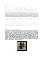
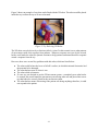
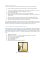
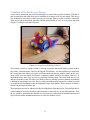

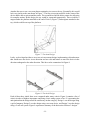
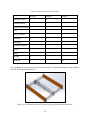
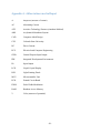
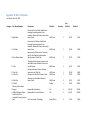
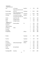
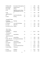
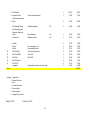
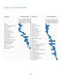
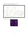
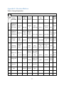
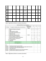
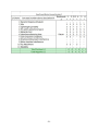
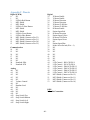
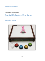
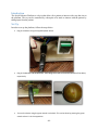
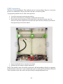


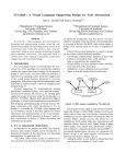
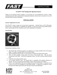


![reply_card [Converted] - TheMysticHelming.mono.net](http://vs1.manualzilla.com/store/data/005649301_1-3a046a309a634867449ff92cdd957a65-150x150.png)