1
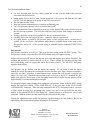
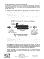
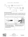
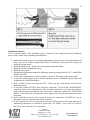
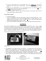
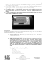
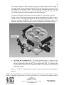
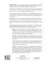
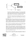
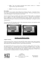
1
INSTRUCTIONS
EZ-EFI™ Self Tuning Fuel Injection System
Thank you for choosing FAST™ products; we are proud to be your manufacturer of choice. Please
read this instruction sheet carefully before beginning installation, and also take a moment to review the
included limited warranty information.
INSTALLATION
System Components Overview
The EZ-EFI™ system is made up of several main components. A throttle body, an ECU (Electronic
Control Unit), a wiring harness, a handheld user interface, several loose sensors and an RPM module.
Please read through all of the installation notes before beginning the installation.
Throttle Body
Throttle Body Installation Notes:
•
•
•
•
•
•
The throttle body will bolt on in place of a carburetor on an intake manifold with a 4150 square
flange. It accepts a standard Holley-style throttle linkage.
When installing the throttle body, it is good practice to replace the throttle body gasket.
There are three manifold vacuum ports on the base of the throttle body. And one ported
vacuum port on the body – near the air temperature sensor. Be sure to cap any unused vacuum
ports.
A throttle return spring should be used.
An air cleaner should be used. The throttle body is compatible with standard carburetor air
cleaners. Be sure to account for hood clearance issues when choosing an air cleaner.
There is some adjustability built into the linkage between the throttle shafts. It should be set up
as close to a one to one arrangement as reasonably possible – as opposed to a progressive setup.
Having all four blades open at the same time gives the best fuel distribution.
FAST™
FAST™
3400 Democrat
Democrat Rd.
Rd.
3400
Memphis, TN
TN 38118
38118
Memphis,
Phone: (901)
(901) 260-3278
260-3278 Fax:
Fax: (901)
(901) 375-3408
366-1807
Phone:
www.fuelairspark.com
www.fuelairspark.com
Part # FAST4-152
Part #???
Revised
Revised 4/19/11
??????
2
ECU
ECU Installation Notes:
•
•
•
•
The ECU is water tight when connected to the wiring harness. It can be mounted in the engine
compartment or in the vehicle’s interior. It is good practice to mount the ECU with the
connector facing down. This way, there is less chance of moisture getting into the ECU if it
needs to be disconnected in wet conditions.
The ECU should not be mounted close to other electrically “noisy” components. In particular,
keep good spacing (try for 2 feet minimum) from ignition components (ignition boxes, coils,
distributors, etc.)
If mounting in the engine compartment, selecting a location towards the rear will make it easier
to route the communications cable to the interior to allow the handheld to be monitored while
driving. (After the initial setup, use of the handheld is optional. It does not need to remain
connected for the engine to run.) Optional, longer communications cables are available if
needed.
There is an LED on the front face of the ECU – the side with the logo. It will flash if the onboard diagnostics detects a problem. (The LED will normally remain off at key-on. Then
come on when the ECU detects an RPM input. It will be lit solid while the engine is running
normally.) To take advantage of this feature, the ECU will need to be mounted so that the front
face of the ECU is visible. The handheld will also indicate if any faults have been detected.
Wiring Harness
Wiring Harness Installation Notes:
•
The main battery wires, labeled “BATTERY POS” and “BATTERY NEG” MUST BE
CONNECTED DIRECTLY to the battery. Connecting them anywhere else invites problems
FAST™
FAST™
3400 Democrat
Democrat Rd.
Rd.
3400
Memphis, TN
TN 38118
38118
Memphis,
Phone: (901)
(901) 260-3278
260-3278 Fax:
Fax: (901)
(901) 375-3408
366-1807
Phone:
www.fuelairspark.com
www.fuelairspark.com
Part # FAST4-152
Part #???
Revised
Revised 4/19/11
??????
3
•
•
•
with electrical noise. These kinds of problems are difficult to diagnose. The wires may be
extended if needed using automotive grade 12 gauge (or larger) wire.
Be sure the “12V SWITCHED” wire is connected to a source that is hot with the key in the
On/Run and Crank positions. Do NOT connect to the positive side of an ignition coil.
The wiring harness should be kept away from ignition components (ignition boxes, coils,
distributors, etc.) as much as possible. There will be places where plug wires run past the
wiring harness. That is often unavoidable and not a problem. Just try to keep them – or other
parts of the ignition system’s wiring – from running parallel to the wiring harness. And do not
bundle the wiring harness together with other “noisy” wiring in the vehicle.
As with any wiring, it is good practice to avoid routing the wiring harness around sharp edges
or near high temperature components such as headers.
The connections on wiring harness are all clearly labeled. They are connected as follows:
Label
Inj 1
Inj 2
Inj 3
Inj 4
Idle Motor
Throttle
Air Temp
MAP
Connects to
Injector #1 in throttle body. (Driver side front)
Injector #2 in throttle body. (Passenger side front)
Injector #3 in throttle body. (Driver side rear)
Injector #4 in throttle body. (Passenger side rear)
Idle Air Control motor (IAC) in rear of throttle body.
Throttle Position Sensor (TPS) on passenger side of throttle body.
Air Temperature Sensor (ATS) on passenger side of throttle body.
Manifold Absolute Pressure sensor (MAP) on driver side of
throttle body.
FAST™
FAST™
3400 Democrat
Democrat Rd.
Rd.
3400
Memphis, TN
TN 38118
38118
Memphis,
Phone: (901)
(901) 260-3278
260-3278 Fax:
Fax: (901)
(901) 375-3408
366-1807
Phone:
www.fuelairspark.com
www.fuelairspark.com
Part # FAST4-152
Part #???
Revised
Revised 4/19/11
??????
4
Coolant Temp
Coolant Temperature Sensor (CTS) typically installed in intake
manifold.
Oxygen Sensor
Wideband oxygen sensor (O2) mounted in exhaust.
Tach In/RPM Module A tach output from an ignition box or other source. Or the EZ-EFI™
RPM Module. Depends on application. See RPM Module notes. Do NOT
connect directly to the ignition coil.
Fuel Pump Controller EZ-EFI™ fuel pump relay harness included in the optional EZ-EFI™ Fuel
Pump kit.
Fuel Pump Relay
Negative control side of a relay for powering a fuel pump. Do NOT wire
directly to fuel pump. (Not used with optional EZ-EFI™ Fuel Pump kit.)
Handheld
Communications cable that links the main wiring harness to the handheld user
interface.
Battery Pos
DIRECTLY to positive post of battery.
Battery Neg
DIRECTLY to negative post of battery.
12V Switched
Switched ignition source (hot in On/Run and Crank). This turns the ECU on
and off. Do NOT connect to the positive side of an ignition coil.
Fan Relay
Negative control side of a relay for powering an electric fan. Do NOT wire
directly to fan.
A/C Input
Air conditioner switch. Feeding power to this wire tells the ECU that the air
conditioner has been switched on. Idle speed will be bumped up and the fan
output will be activated.
FAST™
FAST™
3400 Democrat
Democrat Rd.
Rd.
3400
Memphis, TN
TN 38118
38118
Memphis,
Phone: (901)
(901) 260-3278
260-3278 Fax:
Fax: (901)
(901) 375-3408
366-1807
Phone:
www.fuelairspark.com
www.fuelairspark.com
Part # FAST4-152
Part #???
Revised
Revised 4/19/11
??????
5
RPM Module
EZ-EFI™ is an advanced fuel injection system. Engine speed is one of the fundamental elements of its
fueling calculations. In order for it to operate properly, it relies on the ignition system for a steady,
reliable RPM signal. An inconsistent or noisy RPM signal can appear to the ECU as erratic engine
speed. Spikes, dropouts and general instability of the RPM signal fed into the ECU can have an
adverse effect on the running of the engine. It can also interfere with proper learning or prevent
learning altogether.
There are two basic options for supplying the EZ-EFI™ ECU with an RPM input.
1. Aftermarket capacitive discharge (CD) ignition
An aftermarket capacitive discharge (CD) ignition box is recommended. This form of ignition
is beneficial to just about any application. Having a known good, strong spark prevents a host
of potential running issues. This type of ignition is also well suited for use with EZ-EFI™
because it typically has a “Tach” output which is a clean, processed signal. This is the
preferred RPM source for the EZ-EFI™ system.
If using one of these ignitions, the “TACH IN / RPM MODULE” wire in the EZ-EFI™ wiring
harness is connected directly to the “Tach” output from the ignition box. The RPM Module
included with the kit is not used in this case. And no part of the EZ-EFI™ system is connected
to the coil.
(NOTE: Some aftermarket ignitions have a feature for displaying their programmed rev limit.
This is accomplished by briefly outputting an RPM signal on their tach output wire soon after
key-on. The intent is to have the vehicle’s tachometer display the rev limit setting. This
feature is not well suited for some fuel injection systems – including EZ-EFI™ – as it appears
the engine is actually running at that speed. This can lead to the ECU rapidly pulsing the
injectors (injecting a large quantity of fuel) and flooding the engine. Contact your ignition
vendor to verify whether or not your ignition product has this feature and for details on
disabling it. Keep in mind that it is normal for the EZ-EFI™ system’s “pre-squirt” feature
(discussed in the EZ-EFI™ SYSTEM FEATURES section) to pulse the injectors for a second
or two right at key-on. This feature can be distinguished from a potential ignition issue in
several ways:
• The “pre-squirt” feature will inject a measured amount of fuel – it will not come
anywhere near flooding the engine.
FAST™
FAST™
3400 Democrat
Democrat Rd.
Rd.
3400
Memphis, TN
TN 38118
38118
Memphis,
Phone: (901)
(901) 260-3278
260-3278 Fax:
Fax: (901)
(901) 375-3408
366-1807
Phone:
www.fuelairspark.com
www.fuelairspark.com
Part # FAST4-152
Part #???
Revised
Revised 4/19/11
??????
6
•
•
The “pre-squirt” feature will not continue to occur on subsequent key cycles unless the
engine has been started.
The “pre-squirt” feature will not cause the LED on the face of the ECU to come on
solid when the engine isn’t running as a false RPM signal would. It also won’t cause a
tachometer or the handheld to display a non-zero RPM value.)
2. Inductive coil
Another source for an RPM signal is the negative side of the ignition coil in a traditional dwell
controlled inductive ignition system. One in which the coil is fed power on one side and is
charged by grounding the other side - either by “points” or some form of electronic module.
An HEI is one example of this type of ignition system.
To use this RPM signal option, the RPM Module is required. The RPM Module connects to
the negative side of the coil and outputs a “Tach” signal to the ECU. The RPM Module is
connected as follows:
Wire color
Black
Black
White
Yellow
Connection
Engine block
Engine block
Negative side of coil
“TACH IN / RPM MODULE” wire in EZ-EFI™ wiring harness
The RPM Module is provided to allow this convenient installation option. But keep in mind
that it has limitations. The negative side of an ignition coil is one of the noisiest points on the
engine. There are large voltage spikes and ringing when the coil fires. Different coils will
have different noise characteristics. And this noise can change as the engine runs. Anything
that affects how hard the coil has to work to fire the spark plug – changing cylinder pressure,
worn plugs or plug wires, etc. – will affect this signal.
In most applications, the RPM Module will be able to deal with these challenges and feed a
clean RPM signal to the ECU. But the old saying – garbage in, garbage out - applies here. If
the inductive ignition system is just too noisy or inconsistent, it may need to be abandoned in
favor of an aftermarket ignition box.
RPM Module Installation Notes:
•
•
•
HEI distributors (and possibly others) have a terminal labeled “TACH”. However, that is not a
clean, processed tach signal like an aftermarket ignition box would supply. Instead, it is simply
another terminal connected to the negative side of the coil. Do NOT connect the “TACH IN /
RPM MODULE” wire in the EZ_EFI™ wiring harness directly to that terminal. The ECU will be
damaged. In a case like that, the RPM Module is required since what you are really doing is
connecting to the negative side of a dwell controlled coil.
Do NOT bypass the RPM Module and connect the “TACH IN / RPM MODULE” wire in the EZEFI™ wiring harness directly to the negative side of the coil. It may actually start up and run that
way. But the ECU will be damaged and system performance will degrade.
Do NOT connect anything from the EZ-EFI™ system to the coil – RPM Module or “TACH IN /
RPM MODULE” wire – when using an aftermarket ignition box.
FAST™
FAST™
3400 Democrat
Democrat Rd.
Rd.
3400
Memphis, TN
TN 38118
38118
Memphis,
Phone: (901)
(901) 260-3278
260-3278 Fax:
Fax: (901)
(901) 375-3408
366-1807
Phone:
www.fuelairspark.com
www.fuelairspark.com
Part # FAST4-152
Part #???
Revised
Revised 4/19/11
??????
7
•
•
•
Use resistor type spark plugs. Non-resistor plugs are very noisy and interfere with electronics –
including the EZ-EFI™ system.
Do NOT use solid core spark plug wires. These are also very noisy.
Mechanical issues such as a worn distributor gear can make the time between coil firings
inconsistent – possibly causing the ECU to see an erratic RPM signal. That would apply to either
type of ignition if they are taking their input from a distributor mounted pickup. This is another
example of how a deficiency in the ignition system can affect the performance of the EZ-EFI™
system. Eliminating excessive play in the distributor or installing a crank trigger would help this
situation.
Sensors
Most of the sensors are contained in the throttle body itself. There are just a couple extra sensors that
will need to be mounted.
Coolant Temperature Sensor
This sensor monitors engine coolant temperature. It is typically installed in an existing
mounting hole on the top of the intake manifold. The sensor has 3/8” NPT threads. The
supplied adapter may be required to install the sensor in some manifolds with 1/2" NPT
threads. The engine block or cylinder head may have a provision for mounting a coolant
temperature sensor. Just be aware that heat radiated from headers may be absorbed by the
metal sensor body and skew the temperature readings to the ECU.
Wideband Oxygen Sensor
The wideband oxygen sensor needs to be mounted in the exhaust system. A threaded fitting
and block off plug are provided. The fitting needs to be welded into place. To install the
fitting, drill a .750” diameter hole and weld the fitting centered on the hole. If you do not have
access to a welder, any competent exhaust shop can install the fitting for you. Use the supplied
block off plug (not your actual oxygen sensor) to cap off your new oxygen sensor fitting until
FAST™
FAST™
3400 Democrat
Democrat Rd.
Rd.
3400
Memphis, TN
TN 38118
38118
Memphis,
Phone: (901)
(901) 260-3278
260-3278 Fax:
Fax: (901)
(901) 375-3408
366-1807
Phone:
www.fuelairspark.com
www.fuelairspark.com
Part # FAST4-152
Part #???
Revised
Revised 4/19/11
??????
8
you are ready to complete the rest of the EZ-EFI™ installation. Oxygen sensors use a built in
heater. If the sensor is installed, but not connected, it will not be heated and deposits may build
up in the sensor.
(NOTE: Installing the threaded oxygen sensor fitting should be the first step in the installation
process. It should be done before you begin removing your existing fuel / induction system.
That way, you can still drive to an exhaust shop if needed.)
Wideband Oxygen Sensor Installation Notes:
•
•
•
•
•
•
Install the sensor just upstream of the catalytic converter (if present). The sensor can be
installed after the converter, but the readings will register slightly leaner than if measured
before the converter
Ideally, the sensor should be mounted at least 10* above horizontal (wire side up, sensor tip
down). This prevents moisture from collecting in the sensor.
The sensor should not be installed closer than 20 inches from the cylinder head to ensure
excessive heat does not damage the sensor.
The sensor should be installed in or after the collector. This gives the ECU an average reading
across an entire bank instead of from just one cylinder.
The sensor should not be mounted near the open end of the exhaust system. At low engine
speeds, free air may reverberate into the exhaust and cause false readings.
The system will not function properly if there are any exhaust leaks. Any fresh air that gets to
the sensor will cause false lean readings. The ECU will respond by adding fuel that the engine
doesn’t really need.
(NOTE: The use of leaded fuel will significantly reduce the lifespan of the oxygen sensor.)
Fuel system
The EZ-EFI™ system needs a high pressure, fuel injection rated fuel system. An optional EZ-EFI™
Fuel Pump kit is available that includes the required hardware and wiring. Fuel line and fittings are
also available in an optional EZ-EFI™ Hose and Fitting kit. Whether using these kits or building a
fuel system with other components, the basic layout will be as follows:
•
•
Starting at the tank, a fuel line will run to a pre-filter. (The pump included in the EZ-EFI™ Fuel
Pump kit features a built in strainer in its inlet. So a pre-filter is not required.)
From the pre-filter (if used), a fuel line will connect to the fuel pump inlet. The fuel pump should
be mounted near the tank and low so that it is gravity fed. (NOTE: To avoid damage to the pump,
FAST™
FAST™
3400 Democrat
Democrat Rd.
Rd.
3400
Memphis, TN
TN 38118
38118
Memphis,
Phone: (901)
(901) 260-3278
260-3278 Fax:
Fax: (901)
(901) 375-3408
366-1807
Phone:
www.fuelairspark.com
www.fuelairspark.com
Part # FAST4-152
Part #???
Revised
Revised 4/19/11
??????
9
•
•
•
•
•
do not allow it to run dry.) Depending on the fittings being used, the pre-filter may attach directly
to the fuel pump.
From the fuel pump outlet, a fuel line will connect to a post-filter. Depending on the fittings being
used, the fuel pump outlet may attach directly to the post-filter. This is the case with the EZ-EFI™
Fuel Pump kit.
From the post-filter, a fuel line will connect to one of the fuel rails on the throttle body.
The throttle body comes with a crossover to carry the fuel from one rail to the other.
From the outlet of the second fuel rail, a fuel line will connect to the inlet of the fuel pressure
regulator. If using a dual inlet fuel pressure regulator, be sure to cap the unused port. (The fuel
pressure regulator also needs a vacuum line connecting its vacuum reference port to manifold
vacuum).
From the outlet of the fuel pressure regulator, a fuel line will return bypassed fuel back to the fuel
tank.
CAUTION: Installation of this product requires detailed knowledge of automotive systems and repair
procedures. Installation of fuel system parts and any fuel tank modifications must be carried out by a
qualified automotive technician. Installation of fuel system parts requires handling of gasoline.
Ensure that work is performed in a well ventilated area with an approved fire extinguisher nearby.
Extinguish all open flames, prohibit smoking and eliminate all sources of ignition in the area of the
vehicle before proceeding with the installation. When working with fuel systems, eye goggles and
other safety apparel as needed should be worn to protect against debris and sprayed gasoline. The
finished work must be checked carefully to ensure there are no fuel leaks.
FAST™
FAST™
3400 Democrat
Democrat Rd.
Rd.
3400
Memphis, TN
TN 38118
38118
Memphis,
Phone: (901)
(901) 260-3278
260-3278 Fax:
Fax: (901)
(901) 375-3408
366-1807
Phone:
www.fuelairspark.com
www.fuelairspark.com
Part # FAST4-152
Part #???
Revised
Revised 4/19/11
??????
10
Fuel System Installation Notes:
•
•
•
•
•
•
•
•
•
Use fuel injection rated fuel line, filters, pump, etc. to deal with the higher fuel pressures
associated with fuel injection.
Mount pump close to the fuel tank. Mount pump low so it is gravity fed from the fuel tank.
(NOTE: To avoid damage to the pump, do not allow it to run dry.)
The fuel tank must be vented.
Keep fuel system components away from heat and moving parts.
Use a fuel pressure regulator with a vacuum reference port.
Run a vacuum hose from a manifold vacuum port on the throttle body to the reference port on
the fuel pressure regulator. This will raise and lower fuel pressure with changes in manifold
vacuum.
If using a dual inlet fuel pressure regulator, be sure to cap the unused port.
Carefully inspect the fuel system for leaks – especially when it is pressurized.
It is good practice to install a fuel pressure gauge so fuel pressure can be verified later if
needed. At the very least, a fuel pressure gauge must be available during initial setup so the
fuel pressure can be set. A fuel pressure gauge is included with the optional EZ-EFI™ Fuel
Pump kit.
Fuel pressure
Fuel pressure should be set to 43 psi. This is the baseline setting for the EZ-EFI™ system. This
fuel pressure with the 4 injectors in the EZ-EFI™ throttle body will support 550 hp.
Higher fuel pressure will increase the injector flow rates and support more power if needed. For
example, the injectors are rated at 88 lb/hr @ 60 psi. That is enough fuel for about 650 hp if the
fuel system being used can supply that much fuel at that pressure. The EZ-EFI™ fuel pump
supports about 600 hp.
Fuel pressure can be checked with the engine not running. (If you check it with the engine
running, be sure to disconnect the vacuum line from the reference port. Don’t forget to reconnect it
when you are done! Also keep in mind that the loose vacuum line will become a vacuum leak
unless you cap it off.) Watch the fuel pressure gauge at key-on as the ECU commands the fuel
pump on to prime the fuel system. If the fuel pump needs to be run again, turn the ignition off for
approximately 10 seconds and then back on again.
To manually keep the pump running while setting the fuel pressure, locate in the EZ-EFI™ wiring
harness the green wire labeled “FUEL PUMP RELAY” or the green wire in the “FUEL PUMP
CONTROLLER” connector. These are both connected to the ECU’s fuel pump control. And one
of them should be going to a fuel pump relay (either your own or the one built into the relay
harness in the optional EZ-EFI™ Fuel Pump kit). Ground whichever of those two wires is not
connected. With the ignition on, that should trip the relay and run the pump.
Turning the adjustment screw on the fuel pressure regulator changes the fuel pressure. Be sure to
tighten down the jam nut when finished adjusting the fuel pressure.
FAST™
FAST™
3400 Democrat
Democrat Rd.
Rd.
3400
Memphis, TN
TN 38118
38118
Memphis,
Phone: (901)
(901) 260-3278
260-3278 Fax:
Fax: (901)
(901) 375-3408
366-1807
Phone:
www.fuelairspark.com
www.fuelairspark.com
Part # FAST4-152
Part #???
Revised
Revised 4/19/11
??????
11
EZ-EFI™ Fuel Pump Kit / EZ-EFI™ Hose and Fitting Kit
Optional kits are available that include all of the components needed to assemble a high quality,
fuel injection rated fuel system. The EZ-EFI™ Fuel Pump kit consists of all the basic hardware
(pump, filter, regulator, gauge, etc.) and wiring (plug in fuel pump harness with relay) needed to
assemble the fuel system.
For connecting everything together, an EZ-EFI™ Hose and Fitting kit is available. It includes fuel
line and fittings to mate to the hardware from the EZ-EFI™ Fuel Pump Kit. The fuel pump inlet
uses a hose barb fitting. All other fittings are -6 AN.
EZ-EFI™ Fuel Pump Kit - Pump and Fittings
The EZ-EFI™ Fuel Pump kit includes a high pressure, high flow fuel pump along with the
associated fittings and O-rings. There is a hose barb inlet fitting and a -6 AN outlet fitting. A
third fitting is included but will not be used.
EZ-EFI™ Fuel Pump Kit - Wiring
The EZ-EFI™ Fuel Pump kit includes a relay harness that mates directly to the “FUEL PUMP
CONTROLLER” connector on the main wiring harness. It is packaged with a loose ring
terminal and an insulated butt splice. The fuel pump is packaged with a connector pigtail.
The relay harness has a long, loose red wire that feeds power to the fuel pump. Once this has
been routed and cut to the desired length, use the insulated butt splice to crimp it to the red wire
on the fuel pump connector pigtail. (Be sure to strip some wire insulation off of each wire
first!) After making the connection, use a heat gun to shrink down the insulation.
Attach the ring terminal to the black wire (again, strip off some wire insulation first!) on the
fuel pump connector pigtail. This needs to be grounded. You can often use one of the bolts
that mounts the fuel pump.
FAST™
FAST™
3400 Democrat
Democrat Rd.
Rd.
3400
Memphis, TN
TN 38118
38118
Memphis,
Phone: (901)
(901) 260-3278
260-3278 Fax:
Fax: (901)
(901) 375-3408
366-1807
Phone:
www.fuelairspark.com
www.fuelairspark.com
Part # FAST4-152
Part #???
Revised
Revised 4/19/11
??????
12
EZ-EFI™ Hose and Fitting Kit
The EZ-EFI™ Hose and Fitting kit includes hose clamps for securing fuel line to the fuel
tank’s outlet and return and to the inlet of the fuel pump. A -6 AN female coupling is used to
connect the fuel pump outlet to the post-filter. Push fit -6 AN fittings are used for all other
connections. The ‘Basic Fuel System Layout’ diagram shows where the different fittings are
used.
NOTE: Soaking the hose end in boiling water before assembly will make it more pliable.
FAST™
FAST™
3400 Democrat
Democrat Rd.
Rd.
3400
Memphis, TN
TN 38118
38118
Memphis,
Phone: (901)
(901) 260-3278
260-3278 Fax:
Fax: (901)
(901) 375-3408
366-1807
Phone:
www.fuelairspark.com
www.fuelairspark.com
Part # FAST4-152
Part #???
Revised
Revised 4/19/11
??????
13
Installation Sequence
This is a general outline of the installation process. Read all of the component specific installation
notes for more detail before beginning the installation.
1. Install the threaded oxygen sensor fitting in the exhaust system and cap it off with the block off
plug. Once you are ready to complete the EZ-EFI™ installation, remove the block off plug and
install the oxygen sensor.
2. Install the throttle body. Attach your return spring and throttle linkage.
3. Install the Coolant Temperature Sensor.
4. Install the fuel system.
5. Determine the appropriate method for getting an engine speed input into the ECU. Install RPM
Module if needed.
6. Connect the wiring harness to all of the sensors / injectors / idle motor on the throttle body.
7. Connect the wiring harness to the Coolant Temperature Sensor, Wideband Oxygen Sensor and
an ignition box or the RPM Module.
8. Find a suitable location and mount the ECU. Make sure the wiring harness will reach the
mounting location.
9. If using the optional EZ-EFI™ Fuel Pump Kit, connect the “FUEL PUMP CONTROLLER”
connection on the main wiring harness to the included relay harness. Route the relay harness
back to the fuel pump and make the final connections. Otherwise, connect the “FUEL PUMP
RELAY” wire on the main wiring harness to the negative side of a relay that feeds power to the
fuel pump.
10. If you would like to have the ECU control an electric fan, connect the “FAN RELAY” wire to
the negative side of a relay that feeds power to the fan.
11. If you would like the ECU to bump up the idle speed and activate the fan output when an air
conditioning compressor is switched on, connect the “A/C INPUT” wire to the A/C switch so
that it sees power when the A/C is turned on.
FAST™
FAST™
3400 Democrat
Democrat Rd.
Rd.
3400
Memphis, TN
TN 38118
38118
Memphis,
Phone: (901)
(901) 260-3278
260-3278 Fax:
Fax: (901)
(901) 375-3408
366-1807
Phone:
www.fuelairspark.com
www.fuelairspark.com
Part # FAST4-152
Part #???
Revised
Revised 4/19/11
??????
14
12. Connect the “BATTERY POS” and “BATTERY NEG” wires DIRECTLY to the battery.
Extend the wires if necessary to reach the battery. Use automotive grade 12 gauge (or larger)
wire.
13. Connect the “12V SWITCHED” wire to a switched ignition source (hot in On/Run and Crank).
Do NOT connect to the positive side of an ignition coil.
14. Connect the wiring harness to the ECU
15. Switch on the ignition. The ECU will run the fuel pump for several seconds. Inspect the fuel
system for leaks and set the fuel pressure.
Setup / Initial Cranking
1. Switch on the ignition.
2. Connect the handheld to the main wiring harness using the communications cable. And to
power by connecting the power cable to the handheld and to a cigarette lighter plug. The
handheld power source needs to be hot in On/Run and Crank to ensure the Setup Wizard
routine is not interrupted when the engine is started.
3. Select SETUP WIZARD in the handheld. It will walk you through initial setup and cranking.
HANDHELD
The EZ-EFI™ Handheld serves as the user interface with the EZ-EFI™ system. It has a straight
forward menu system that offers advanced features without requiring a laptop or any computer skills.
Its first task is to take you through the Setup Wizard. It also serves as a scan tool by displaying live
data and diagnostics information. Beyond basic setup, you can also adjust other settings to suit your
engine – rev limiter, target air/fuel ratios, etc. After the initial setup, use of the handheld is optional. It
does not need to remain connected for the engine to run.
Handheld Notes:
•
•
The handheld has two cables that must be connected. A communications cable that links the
handheld to the “HANDHELD” connector on the main wiring harness. And a power cable that
goes to a cigarette lighter receptacle. The handheld power source needs to be hot in On/Run and
Crank to ensure the Setup Wizard routine is not interrupted when the engine is started.
To avoid potential communications problems or damage to the handheld or ECU, make sure the
cigarette lighter receptacle has sound, reliable wiring to power and ground and that the receptacle
FAST™
FAST™
3400 Democrat
Democrat Rd.
Rd.
3400
Memphis, TN
TN 38118
38118
Memphis,
Phone: (901)
(901) 260-3278
260-3278 Fax:
Fax: (901)
(901) 375-3408
366-1807
Phone:
www.fuelairspark.com
www.fuelairspark.com
Part # FAST4-152
Part #???
Revised
Revised 4/19/11
??????
15
•
•
•
itself is in good shape with no corrosion. The handheld should get its power and ground from the
same electrical system as the ECU.
To turn off the handheld, disconnect the power cable either at the handheld itself or from the
cigarette lighter receptacle. Reconnect the power cable to restart the handheld.
If the handheld displays a “COMM ERROR” message, make sure the handheld’s communication
cable is connected and that the ECU is powered on. Then press the RESET button on the
handheld.
If you will be monitoring live data or making adjustments while driving, be safe and bring a friend
along to operate the handheld while you drive.
Setup Wizard
The EZ-EFI™ Setup Wizard will walk you through the initial ECU setup. Once you select SETUP
WIZARD from the main menu, you will be asked...
•
START A NEW TUNE? YES will let you continue the setup wizard. NO will take
you back to the main menu.
•
RESET ECU TO BASE TUNE? The Setup Wizard takes the answers to several basic
questions and configures the ECU for your engine. Through the Advanced Options
menu in the handheld, you can adjust specific settings to your liking. Selecting YES at
this prompt will overwrite those adjustments back to the pre-programmed starting
points already contained in the ECU. It will also erase any learning the ECU has
already done. Selecting NO will leave those adjustments and any learning in place and
only perform the basic setup procedures – fueling and TPS calibration and setting idle
speed.
The settings that will be reset by selecting YES are:
Learning
Rev Limiter
Air/Fuel Ratio Targets
Accel Fuel adjustments
Electric Fan turn on temperature
FAST™
FAST™
3400 Democrat
Democrat Rd.
Rd.
3400
Memphis, TN
TN 38118
38118
Memphis,
Phone: (901)
(901) 260-3278
260-3278 Fax:
Fax: (901)
(901) 375-3408
366-1807
Phone:
www.fuelairspark.com
www.fuelairspark.com
Part # FAST4-152
Part #???
Revised
Revised 4/19/11
??????
16
On a fresh installation, either response is appropriate and gives the same results since
there will have been no learning or adjustments made yet.
•
ENGINE CUBIC INCHES. Enter your engine size.
•
IDLE SPEED. Enter your desired idle speed. This can be adjusted independently later
through the Advanced Options menu.
•
EZ-EFI™ THROTTLE BODY? If using the EZ-EFI™ throttle body, select EZEFI
SINGLE. If using a dual quad setup with two EZ-EFI™ throttle bodies, select EZEFI
DUAL. If using an Inglese™ induction system, select INGLESE EFI. If using some
other arrangement of throttle body and injectors (such as a multi-port fuel injection
setup), select OTHER.
•
INGLESE KIT PART NUMBER. (Skipped if not using an Inglese™ induction
system.) Select the injector kit part number purchased with the Inglese™ induction
system.
•
NUMBER OF INJECTORS. (Skipped if using EZ-EFI™ throttle bodies or an
Inglese™ induction system) Enter the number of injectors you are using.
•
INJECTOR FLOW AT 43 PSI. (Skipped if using EZ-EFI™ throttle bodies or an
Inglese™ induction system). Injectors are rated for a certain flow rate (in lbs/hr) at a
given pressure. 43 psi (or 3 Bar) is a common pressure for injector flow ratings. If your
injectors were rated at a different pressure their flow rating needs to be converted to 43
psi. The formula for converting the flow rate is:
New flow = Old flow * square root of (New pressure / Old pressure)
As an example, assume your injector’s flow rating is 65 lb/hr @ 58 psi. The flow rating
@ 43 psi is calculated as follows…
New flow = 65 * square root of (43/58)
New flow = 56
•
FUEL PRESSURE. Enter the fuel pressure you will be using. For the EZ-EFI™
throttle bodies, 43 psi is the recommended pressure. This fuel pressure with the 4
injectors in the EZ-EFI™ throttle body will support 550 hp.
Higher fuel pressure will increase the injector flow rates and support more power if
needed. For example, the injectors are rated at 88 lb/hr @ 60 psi. That is enough fuel
for about 650 hp if the fuel system being used can supply that much fuel at that
pressure. The EZ-EFI™ fuel pump supports about 600 hp.
(NOTE: Entering a fuel pressure at this prompt is telling the ECU what pressure the
fuel system is set to. It does not actually set the fuel pressure. Fuel pressure must be set
/ verified with a fuel pressure regulator and gauge.)
FAST™
FAST™
3400 Democrat
Democrat Rd.
Rd.
3400
Memphis, TN
TN 38118
38118
Memphis,
Phone: (901)
(901) 260-3278
260-3278 Fax:
Fax: (901)
(901) 375-3408
366-1807
Phone:
www.fuelairspark.com
www.fuelairspark.com
Part # FAST4-152
Part #???
Revised
Revised 4/19/11
??????
17
•
NUMBER OF CYLINDERS. Enter the number of cylinders your engine has.
•
TPS CALIBRATION SCREENS. The throttle position sensor (TPS) sends a voltage
to the ECU that varies with throttle movement. The ECU needs to know what voltage
corresponds to closed and full throttle. You will be asked to leave the throttle at the idle
/ closed position. Once that value is captured, you’ll be asked to hold the throttle wide
open. The Setup Wizard will tell you how long to hold the throttle open while it
captures that value. Once the handheld has captured the full throttle value and advanced
past the TPS Calibration screen, be sure to return the throttle to the idle / closed
position.
(NOTE: The full throttle procedure is meant to be performed with the engine NOT
running!)
The basic setup is complete! The next step is to start the engine and let it warm up. If
necessary, open the throttle blades (by adjusting the idle screw on the throttle body) enough
to keep the engine running. The handheld will display a warm up screen. A bar graph will
move toward a “target” as the engine warms up. Once it has warmed up, the handheld will
automatically advance to the Throttle Blade Adjustment screen.
(NOTE: There is also an upper temperature limit. If the engine has been run and is too hot,
the handheld will wait for it to cool before advancing to the Throttle Blade Adjustment
screen.)
•
THROTTLE BLADE ADJUSTMENT. This screen shows another bar and a “target”.
It also shows the current engine speed. Adjust the idle screw on the throttle body until
the engine is idling close to the idle speed you entered earlier and the bar is roughly
centered on the “target”. This is adjusting the resting position of the throttle blades so
that the idle motor (an electronically controlled stepper motor that allows air to bypass
the throttle blades) is operating in the preferred position. This ensures that the idle
motor has enough range of motion to help bring the idle speed up or down as needed.
(NOTE FOR 500 CID or LARGER ENGINES: The idle motor’s entire range of movement
is from 5 to 180 “counts”. Higher counts mean the idle motor is open more and allowing
more air to bypass the throttle blades. Adjusting the throttle blade so that the bar is roughly
centered on the “target” will put the idle motor at approximately 20 counts at idle [out of
gear] on a fully warmed up engine [coolant temperature over 170F]. This setting will work
well for most engines. For larger engines, the throttle blades may need to be adjusted
differently. If the engine struggles or stalls when the gas pedal is released, the throttle
blades may need to be opened up slightly. This will cause the idle motor to operate at a
more closed position (lower counts) at idle. Since it will have more room to open when the
engine speed dips, it will be able to bypass more air to keep the engine running. In the
Throttle Blade Adjustment screen, adjusting the throttle blades to get the bar towards the
left side of the “target” will cause the idle motor to operate at a more closed position. Idle
motor position can be viewed in the Live Data screens. It is labeled “IAC”.
FAST™
FAST™
3400 Democrat
Democrat Rd.
Rd.
3400
Memphis, TN
TN 38118
38118
Memphis,
Phone: (901)
(901) 260-3278
260-3278 Fax:
Fax: (901)
(901) 375-3408
366-1807
Phone:
www.fuelairspark.com
www.fuelairspark.com
Part # FAST4-152
Part #???
Revised
Revised 4/19/11
??????
18
If the engine struggles or stalls when the gas pedal is released with the standard “center of
the target” setup, you can run back through the basic Setup Wizard [you can answer NO on
the “RESET ECU TO BASE TUNE?” screen to retain any other adjustments you’ve made
through the Advanced Options menu and any learning that has already occurred.] This will
give you the chance to set the bar towards the left side of the target.
Or instead of using the Setup Wizard, you can watch the IAC counts on the Live Data
display. As you slowly adjust the idle screw to open up the throttle blades, the IAC counts
should decrease. After making the adjustment, the TPS will need to be recalibrated. This is
done by selecting CALIBRATE TPS in the ADVANCED OPTIONS section of the
handheld. Remember to turn the engine off before calibrating the full throttle position.)
•
TPS IDLE RE-CALIBRATION. The throttle position sensor is connected to the
throttle shaft. So adjusting the resting position of the throttle blades in the previous step
may have changed the voltage the ECU is receiving from the TPS. To account for this,
you will again be asked to leave the throttle at the idle / closed position and let the ECU
capture that voltage.
That’s it! The ECU is configured for your engine and is ready to get to work learning more
about it.
(NOTE: The Setup Wizard uses some of the user entries (throttle body type, Inglese Kit Part Number,
Number of Injectors, Injector Flow at 43 PSI, Fuel Pressure, etc.) to perform calculations related to
FAST™
FAST™
3400 Democrat
Democrat Rd.
Rd.
3400
Memphis, TN
TN 38118
38118
Memphis,
Phone: (901)
(901) 260-3278
260-3278 Fax:
Fax: (901)
(901) 375-3408
366-1807
Phone:
www.fuelairspark.com
www.fuelairspark.com
Part # FAST4-152
Part #???
Revised
Revised 4/19/11
??????
19
fuel flow rates. The results are what actually get written to the ECU’s memory – not the individual
entries themselves (Fuel Pressure, etc.) So any time you run through the setup wizard, it will display
the same default values. This is not an indication of a problem. The ECU does retain the calculated fuel
flow information.)
Live Data
The Live Data feature allows you to monitor various engine parameters in real time. There are several
screens that can be selected using the UP and DOWN arrows. The screens are labeled with small
numbers in their lower right corners. These should not be confused with sensor readings. TPS, ATS
and RPM values are all displayed above the sensor labels. To return to the main menu, press the
ENTER/POWER button.
In addition to live data readings, the Live Data screens also feature several Status Indicators. They
show when certain conditions are met. In this picture, the SE indicator is “off”. The AL indicator is
“on”.
Status Indicator
SE
Meaning
System Error. This indicates that an error code has been set. It acts like
a Check Engine Light. Select Error Codes from the main menu to check
and clear error codes.
AL
Adaptive Learning. This indicates that all of the enable conditions for
learning are met and that learning is currently enabled. This can be used
as feedback to give the driver a feel for when the ECU will or will not
learn.
O2
Wideband oxygen (O2) sensor. This indicates the sensor is warmed up
and functioning. The oxygen sensor has an internal heater to keep it at
the correct operating temperature. The warm up process begins at keyon. If the engine has cooled completely in particularly cold weather,
giving the sensor some time to heat up (allowing 10-15 seconds between
key-on and cranking) may contribute to smoother starting. Until the
oxygen sensor has warmed up and begun functioning properly, there will
be no closed loop fuel control.
AC
Air Conditioning input. This indicates that power is applied to the “A/C
INPUT” wire in the wiring harness. This tells the ECU that the A/C
compressor has been turned on. The ECU will bump up the idle speed to
compensate for the extra load. It will also activate the fan output.
FAST™
FAST™
3400 Democrat
Democrat Rd.
Rd.
3400
Memphis, TN
TN 38118
38118
Memphis,
Phone: (901)
(901) 260-3278
260-3278 Fax:
Fax: (901)
(901) 375-3408
366-1807
Phone:
www.fuelairspark.com
www.fuelairspark.com
Part # FAST4-152
Part #???
Revised
Revised 4/19/11
??????
20
• DASH 1
RPM
Engine speed in Revolutions Per Minute.
O2C%
Current closed loop correction based on the reading from the wideband oxygen
(O2) sensor. This is the percent of fuel being added or removed (displays as a
negative number) to achieve the target air/fuel ratio. As the ECU learns more
and more, this will tend to get smaller and smaller in steady state driving.
AF
Air/Fuel ratio. The reading from the wideband oxygen sensor. This should be
close to the Target Air/Fuel ratio. The right side of the scale is leaner.
TAF
Target Air/Fuel ratio. The ratio the ECU is working to maintain. This is
determined by the AF TARGETS settings available in the ADVANCED
OPTIONS section of the handheld. The right side of the scale is leaner.
• DASH 2
RPM
Engine speed in Revolutions Per Minute.
CTS(F) Coolant Temperature Sensor. Displayed in *F. This is the temperature of the
engine. Being above 140*F is one of the enable conditions for learning to
become active.
FAST™
FAST™
3400 Democrat
Democrat Rd.
Rd.
3400
Memphis, TN
TN 38118
38118
Memphis,
Phone: (901)
(901) 260-3278
260-3278 Fax:
Fax: (901)
(901) 375-3408
366-1807
Phone:
www.fuelairspark.com
www.fuelairspark.com
Part # FAST4-152
Part #???
Revised
Revised 4/19/11
??????
21
IAC
TPS%
Idle Air Control. This is the position of the idle motor. At idle, it will move
around to maintain the target idle speed. Displayed in “counts”. Higher counts
mean the idle motor is open more and allowing more air to bypass the throttle
blades. It’s range is from 5 to 180. Generally, this will be around 20 idling out
of gear with a fully warmed up engine.
(NOTE FOR 500 CID or LARGER ENGINES: For large engines, opening up
the throttle blades slightly at idle may help prevent the engine from struggling or
stalling when the gas pedal is released. If this adjustment is made, the idle
motor will operate at a more closed position (lower counts) at idle. Since it will
have more room to open when the engine speed dips, it will be able to bypass
more air to keep the engine running. )
Throttle Position Sensor. This tells you how far the throttle blades are open. Its
range is from 0 (resting idle position) to 100 (full open position). The Setup
Wizard takes care of calibrating this sensor. It can easily be verified using this
display. (NOTE: The TPS value is the large number displayed above the
“TPS%” text. The small “2” in the corner is the page number.) If you ever
notice the TPS reading is not 0 at idle, it should be re-calibrated. This can be
done by going back through the Setup Wizard or by selecting CALIBRATE TPS
in the ADVANCED OPTIONS section of the handheld.
• DASH 3
AF
Air/Fuel Ratio. This is the current reading from the wideband oxygen sensor.
BAT(V) Battery voltage.
MAP
Manifold Absolute Pressure. This is a measure of the load on the engine. It is
displayed in kPa (kilopascals). Its range is from 0 kPa (a perfect vacuum) to 105
kPa. 101 kPa is atmospheric pressure in standard conditions. With the engine
off, this will read around 101 kPa. Then drop down when the engine is started.
ATS(F) Air Temperature Sensor. Displayed in *F. This is the temperature of the air
entering the throttle body. . (NOTE: The ATS value is the large number
displayed above the “ATS (F)” text. The small “3” in the corner is the page
number.)
FAST™
FAST™
3400 Democrat
Democrat Rd.
Rd.
3400
Memphis, TN
TN 38118
38118
Memphis,
Phone: (901)
(901) 260-3278
260-3278 Fax:
Fax: (901)
(901) 375-3408
366-1807
Phone:
www.fuelairspark.com
www.fuelairspark.com
Part # FAST4-152
Part #???
Revised
Revised 4/19/11
??????
22
• DASH 4
INJ DC% Injector Duty cycle. This is a comparison of how long the injectors are open
compared to how much total time is available for them to be open. If this
reaches 100%, it means the injectors physically cannot flow any more fuel.
They are already open for as long as they possibly can be given the current
engine RPM.
LOAD% Calculated load. A comparison of the current manifold pressure vs. the ambient
atmospheric pressure. Unlike the reading from the MAP sensor – which is
affected by altitude – Load should always be consistent. That is, wide open
throttle should ways be around 100% regardless of altitude and ambient
atmospheric pressure.
FUEL LB Current total fuel flow rate into the engine. Given in pounds per hour. This can
be used to get a rough approximation of current engine power.
Horsepower = Fuel Flow (lbs/hr) x 2
RPM
Engine speed in Revolutions Per Minute. (NOTE: The RPM value is the large
number displayed above the “RPM” text. The small “4” in the corner is the
page number.)
FAST™
FAST™
3400 Democrat
Democrat Rd.
Rd.
3400
Memphis, TN
TN 38118
38118
Memphis,
Phone: (901)
(901) 260-3278
260-3278 Fax:
Fax: (901)
(901) 375-3408
366-1807
Phone:
www.fuelairspark.com
www.fuelairspark.com
Part # FAST4-152
Part #???
Revised
Revised 4/19/11
??????
23
Advanced Options
The Advanced Options menu allows you make adjustments beyond the basic settings configured by the
Setup Wizard. These changes can be made at any time – including while the engine is running.
•
IDLE SPEED. Some engines like to idle higher than others. This setting allows you to
easily try different idle speeds to see what works best for yours. Keep in mind that this
is setting the idle speed for a fully warmed up engine. If the engine is cold, the ECU
will try to maintain a slightly higher idle than called for here. If you make large
changes here, you may want to run back through the basic Setup Wizard (you can
answer NO on the “RESET ECU TO BASE TUNE?” screen to retain any other
adjustments you’ve made through the Advanced Options menu and any learning that
has already occurred.) This will help you adjust the resting position of the throttle
blades so that the idle motor is operating in the preferred range.
It is worth noting that once the idle motor is in its fully closed position (the Live Data
display shows IAC at 5), it can not bring the idle speed down any further no matter what
setting is entered here. If this happens, you will need to adjust the idle screw on the
throttle body to close the blades more. (Again, you’ll want to run back through the
basic Setup Wizard afterwards.) The other extreme is if the Live Data display shows
IAC at 180. At that point, the idle motor is fully open and is unable to let any more air
into the engine to raise the idle speed.
•
CALIBRATE TPS. The throttle position sensor is calibrated in the Setup Wizard.
This lets you repeat that process by itself. Just like in the Setup Wizard, you will be
asked to leave the throttle at the idle / closed position. Once that value is captured,
you’ll be asked to hold the throttle wide open.
(NOTE: The full throttle procedure is meant to be performed with the engine NOT
running!)
FAST™
FAST™
3400 Democrat
Democrat Rd.
Rd.
3400
Memphis, TN
TN 38118
38118
Memphis,
Phone: (901)
(901) 260-3278
260-3278 Fax:
Fax: (901)
(901) 375-3408
366-1807
Phone:
www.fuelairspark.com
www.fuelairspark.com
Part # FAST4-152
Part #???
Revised
Revised 4/19/11
??????
24
•
REV LIMITER. To protect the engine from an over speed condition, the maximum
allowable speed can be restricted with this setting. When RPM reaches this value, the
injectors will be disabled. Once RPM has dropped, injection will resume.
(NOTE: Keep in mind that the Rev Limiter will prevent the engine from spinning itself
too fast under its own power. But it does not protect against something else spinning
the engine too fast – such as a downshift into a gear that is too low.)
The Rev Limiter can act as a form of “valet mode”. You can temporarily set the limiter
to a lower RPM if you have to turn your keys over to someone who shouldn’t be using
full engine power. Just remember to set it back afterwards to avoid a surprise the next
time you drive!
•
AF TARGETS. The ECU is constantly working to keep the air/fuel ratio at the current
target air/fuel ratio. The ECU is preloaded with typical targets. This is where those
targets can be adjusted if desired. Keep in mind that a higher number means a “leaner”
air/fuel ratio – less fuel. And a lower number means a “richer” air/fuel ratio – more
fuel.
Different operating conditions require different air/fuel ratios. The EZ-EFI™ system
distills these different requirements down to three simple settings. Any of them can be
adjusted while the engine is running so different settings can be evaluated.
Idle AF – This is the target when the engine is idling. This can have a
pronounced effect on idle quality. It is worth experimenting with to see what
your engine likes. If you notice the engine struggle or if RPM dips considerably
with load changes at idle (going into gear or turning steering wheel to full lock,
for example), it may prefer a richer Idle Air/Fuel target.
Cruise AF – Once the engine is above idle, it will switch to using this target.
The engine will spend the vast majority of its time in this area. So this setting
has the largest effect on your fuel mileage. A leaner target (higher number) will
use less fuel.
Because these settings are so simple to adjust, you may consider changing them
for special situations. If you were going on a long, relaxed highway run, you
could temporarily set this a little bit leaner to maximize fuel economy. Then set
it back for normal around town driving.
WOT AF – Once the engine starts to see more load (LOAD value around 50%
or higher), the ECU will start transitioning from using the Cruise Air/Fuel target
to using this Wide Open Throttle Air/Fuel target. By the time the engine is
under full load, the ECU will be using this target. For intermediate loads, the
ECU interpolates between the Cruise and WOT targets. That is, it changes its
target from the Cruise setting to the WOT setting in proportion to how much the
load has changed from a cruising load to full load.
FAST™
FAST™
3400 Democrat
Democrat Rd.
Rd.
3400
Memphis, TN
TN 38118
38118
Memphis,
Phone: (901)
(901) 260-3278
260-3278 Fax:
Fax: (901)
(901) 375-3408
366-1807
Phone:
www.fuelairspark.com
www.fuelairspark.com
Part # FAST4-152
Part #???
Revised
Revised 4/19/11
??????
25
Target AF Ratio
Cruise AF Target
WOT AF Target
~ 50%
100%
Engine Load
Just as the Cruise Air/Fuel target can be adjusted for fuel economy, the WOT
Air/Fuel target can be adjusted for maximum power. It is quite possible that the
engine can make more power at an air/fuel ratio that is leaner (higher number)
than the preloaded WOT Air/Fuel target. Or it might prefer a richer (lower
number) air/fuel ratio. This is less likely, but it all depends on the engine.
Remember that an air/fuel ratio that is too lean (higher number) can cause severe
engine damage – especially at WOT! When changing any of the targets to a
leaner value, do so in small increments and pay close attention for any signs of
detonation, etc.
•
ACCEL FUEL. When the throttle is opened quickly, the engine needs an extra dose of
fuel for smooth operation. In electronic fuel injection, this is commonly referred to as
Acceleration Enrichment or Accel Fuel. It is very similar to the accelerator pump on a
carburetor. The ECU is preloaded with typical settings for Accel Fuel. This feature
allows you to adjust those settings for more or less Accel Fuel by selecting a positive or
negative adjustment factor. Selecting zero leaves the ECU to use the preloaded values.
(NOTE: Accel Fuel is a fine tuning detail to adjust how the engine responds to throttle
changes. It should only be adjusted after the ECU has had some time to learn and the
engine is running well in steady state operation - throttle not changing.)
Tuning Accel Fuel is a subjective process. You may be able to feel that it’s not quite
right, but it can sometimes be difficult to tell which way the adjustment needs to go.
The places you may notice it are free-revving the engine in neutral, pulling away from a
stop or any time the throttle is opened quickly. The Accel Fuel adjustment applies to all
of these situations. The best setting will be the one that works well for all of them. Not
necessarily the setting that makes one specific situation absolutely perfect as that may
require too much compromise in the others.
If there is too much Accel Fuel, when the throttle is opened quickly, the engine will
sometimes feel as if it is struggling and/or generally not running cleanly. If there is too
FAST™
FAST™
3400 Democrat
Democrat Rd.
Rd.
3400
Memphis, TN
TN 38118
38118
Memphis,
Phone: (901)
(901) 260-3278
260-3278 Fax:
Fax: (901)
(901) 375-3408
366-1807
Phone:
www.fuelairspark.com
www.fuelairspark.com
Part # FAST4-152
Part #???
Revised
Revised 4/19/11
??????
26
little Accel Fuel, you may notice a delay from when you open the throttle to when the
engine responds.
The Live Data feature may be useful in tuning Accel Fuel. Having somebody watch the
live Air/Fuel Ratio (AFR) data (either the numeric display or the bar graph) while you
drive and make quick throttle changes may reveal whether the engine is getting too
much or too little Accel Fuel. When the throttle is opened quickly, there is a lot going
on. AFR will often swing back and forth. You want to watch for an overall trend.
As with most settings, it is good practice to make small, incremental changes and see
what happens. If you make large changes to Accel Fuel, it is possible that you can go
from too little to too much fuel without realizing you’ve passed right over the setting
that makes the engine the happiest.
The Accel Fuel setting can also be used as a troubleshooting tool for a specific type of
installation problem. If the EZ-EFI™ system does not have a good ground connection
to the battery, it is possible for the various sensor readings to appear jumpy to the ECU.
(This jumpiness in the sensor readings may or may not show up on the handheld’s Live
Display screens.) This can fool the ECU into repeatedly invoking the Accel Fuel
feature causing extra fuel to be injected. This could lead to an overly rich and unstable
idle and prevent the ECU from learning. Once the engine is fully warmed up, if
temporarily turning the Accel Fuel setting all the way down makes the engine idle
noticeably better (or conversely, if turning it all the way up makes it idle worse), that
could indicate a bad ground or some other source of noise. After the test, remember to
set the Accel Fuel setting back to its previous value.
•
MORE. This brings up another page of Advanced Options.
•
FAN ON TEMP. This sets the engine temperature that will activate the Fan output.
When the temperature exceeds this limit, the Fan output wire switches to ground to
control a relay. Do NOT wire the Fan output directly to a fan. Once the temperature
has dropped 20*, the Fan output will be deactivated.
FAST™
FAST™
3400 Democrat
Democrat Rd.
Rd.
3400
Memphis, TN
TN 38118
38118
Memphis,
Phone: (901)
(901) 260-3278
260-3278 Fax:
Fax: (901)
(901) 375-3408
366-1807
Phone:
www.fuelairspark.com
www.fuelairspark.com
Part # FAST4-152
Part #???
Revised
Revised 4/19/11
??????
27
•
INFO. This screen displays information about software versions, etc.
support staff may request this information.
•
DONE. This will take you back to the main menu.
Technical
Error Codes
The EZ-EFI™ system includes advanced Diagnostics and Engine Protection / Limp Mode features.
These features are described in detail elsewhere in these instructions. This screen is where any error
codes will be displayed. It is also where they can be cleared.
If an error code has been set, the LED on the front face of the ECU flashes rapidly as a warning that
there is a problem. (The LED will normally remain off at key-on. Then come on when the ECU
detects an RPM input. It will be lit solid while the engine is running normally.) Also, the SE Status
Indicator displayed on the Live Data screens acts like a Check Engine Light. It will signal if an error
code has been set.
The picture on the left is showing error codes. After clearing them, the picture on the right shows what
the Error Codes screen normally looks like.
EZ-EFI™ SYSTEM FEATURES
Adaptive Learning
In their most basic form, electronic fuel injection (EFI) systems compare various inputs (primarily
engine speed and load) to pre-programmed “base fuel tables” stored in the ECU. These fixed base fuel
tables tell the ECU how much fuel to inject for a given engine speed and load.
All competent EFI systems use an oxygen sensor to monitor the resulting air/fuel ratio in real time.
The better systems use a “wideband” oxygen sensor as used in the EZ-EFI™ system. The reading
from the wideband oxygen sensor provides very accurate feedback to the ECU so it knows if more or
less fuel is needed to achieve the desired air/fuel ratio. Adjusting the fueling based on feedback from
an oxygen sensor is commonly referred to as “closed loop” fuel control.
FAST™
FAST™
3400 Democrat
Democrat Rd.
Rd.
3400
Memphis, TN
TN 38118
38118
Memphis,
Phone: (901)
(901) 260-3278
260-3278 Fax:
Fax: (901)
(901) 375-3408
366-1807
Phone:
www.fuelairspark.com
www.fuelairspark.com
Part # FAST4-152
Part #???
Revised
Revised 4/19/11
??????
28
Closed loop fuel control is a very powerful feature. It constantly makes fueling adjustments to
compensate for different engine conditions. It is at its best when operating with well tuned base fuel
tables. Developing good base fuel tables requires significant time and experience. Closed loop fuel
control can help compensate for less than perfect base fuel tables. However, there are limits to what it
can do. It is not a substitute for proper tuning. The more work closed loop has to do, the less
efficiently it can keep the actual air/fuel ratio close to the target ratio.
The Adaptive Learning feature of the EZ-EFI™ system goes beyond normal closed loop fuel control.
Besides using the oxygen sensor feedback to adjust instantaneous fueling, it also uses it to adjust the
underlying base fuel table so that over time, it tunes itself. Closed loop fuel control is happily left with
only fine adjustments to make.
The theory of the Adaptive Learning feature is pretty straight forward. Actually implementing it is
rather complicated. But all of that work is built into the ECU already. All that is left to do is drive.
Operational Notes:
•
•
•
•
•
•
•
The EZ-EFI™ system has a “pre-squirt” feature that helps starting by injecting a measured
amount of fuel into the manifold at key-on. A clicking sound can be heard from the throttle
body as the injectors pulse. Once this feature has been activated (key-on, fuel injectors cycled),
it will be disabled until the engine has run. This prevents flooding the engine if the ignition has
to be cycled on and off for whatever reason.
A “flood clear” mode is available if the engine does somehow become flooded and does not
want to start. If the throttle is held open past 80% while cranking, no fuel will be injected.
Continue to hold the throttle open while cranking. Once the extra fuel is purged and the engine
starts to fire, release the throttle and allow the engine to settle on its own.
In normal conditions, it is good practice (but not strictly required) to key-on and listen for the
“pre-squirt” feature (injectors clicking in the throttle body) to finish before cranking the engine.
This takes about 2 seconds to complete.
The wideband oxygen sensor has an internal heater to keep it at the correct operating
temperature. The warm up process begins at key-on. If the engine has cooled completely in
particularly cold weather, giving the sensor some time to heat up (allowing 10-15 seconds
between key-on and cranking) may contribute to smoother starting. The O2 Status Indicator in
the Live Data screens will indicate when the oxygen sensor has warmed up and begun
functioning properly. Until then, there will be no closed loop fuel control.
The ECU is programmed to inject extra fuel during cranking. This is sufficient to allow most
engines to start on their own. However, if the engine seems to want it, pressing the gas pedal
while cranking will add more fuel. If using this feature, start with small pedal movements to
avoid adding too much fuel and flooding the engine.
Moving the pedal during the first several seconds after key-on (as the fuel pump is being
primed) will also cause additional fuel to be injected. This has the effect of adding additional
“pre-squirt” fuel. This is typically not required. Care should be taken to avoid accidentally
moving the pedal during this time.
Learning does not begin until the engine is warmed up. Coolant temperature must be above
140* F for learning to begin.
FAST™
FAST™
3400 Democrat
Democrat Rd.
Rd.
3400
Memphis, TN
TN 38118
38118
Memphis,
Phone: (901)
(901) 260-3278
260-3278 Fax:
Fax: (901)
(901) 375-3408
366-1807
Phone:
www.fuelairspark.com
www.fuelairspark.com
Part # FAST4-152
Part #???
Revised
Revised 4/19/11
??????
29
•
•
•
•
•
•
•
•
There are various qualifying conditions that must be satisfied for learning to take place. This
prevents the ECU from learning from inappropriate feedback. Many of the learning qualifiers
have to do with making sure the engine is in a steady state condition – no rapid changes. The
AL Status Indicator in the Live Data screens will indicate when learning is enabled. This can
be used as feedback to give the driver a feel for when the ECU will or will not learn.
Learning will take place automatically as the vehicle is driven. No special procedures need to
be followed. Just drive normally. However, it is possible to help speed up the learning process
on a fresh installation. A good method is to open the throttle a small amount and hold the pedal
steady. Let the vehicle accelerate up through the gears. Hold the pedal steady as long as
reasonably possible. Slow down and repeat the process several times using larger throttle
openings each time. It is NOT required that you go through this process with every throttle
position. Don’t do anything to risk your safety or that of other motorists!
While the ECU is still going through the initial learning process, you may discover driving
conditions where the engine is not perfectly happy. This is a natural part of the learning
process. Unless the engine is really unhappy, don’t try to avoid those conditions. Instead,
gently return there and allow the ECU to learn what the engine wants. It should soon feel much
better.
Changes made to the tune in the ECU – through learning or handheld adjustments – are held in
short term memory within the ECU until the next key-off. At that time, the changes are saved
into long term memory. This is another reason why the “BATTERY POS” and “BATTERY
NEG” wires must be connected directly to the battery. If all power (“12V SWITCHED” and
“BATTERY POS”) is cut to the ECU at one time, any new learning will be lost. Once a proper
power down sequence has occurred (approximately 5-10 seconds from key-off), the battery
leads can be disconnected, or the ECU can be disconnected from the wiring harness if
necessary. Once saved into long term memory, your tune can remain in an un-powered ECU
for years.
Using nitrous oxide injection with the EZ-EFI™ system is not recommended. Keep in mind
that the ECU is using closed loop fuel control. If will faithfully do all it can to keep the air/fuel
ratio at the targets you’ve set. If additional fuel is delivered through a wet nitrous system, the
ECU will see that the air/fuel ratio is richer than you’ve requested. The ECU will begin
reducing the amount of fuel it is injecting itself to compensate for the extra fuel from the wet
system. The result could be a dangerously lean condition. Technically, it would be possible to
temporarily adjust the WOT air/fuel ratio target to a suitably rich mixture if a nitrous system
was going to be used. However, this should only be attempted with great caution and is NOT
recommended. Keep in mind that the richer air/fuel target will be in effect whether or not the
nitrous system is activated. This can adversely affect how the engine runs and how the ECU
learns.
The EZ-EFI™ system is intended for naturally aspirated engines only – no turbos or
superchargers.
The EZ-EFI™ system was designed for use with conventional gasoline. It has not been
officially tested for compatibility with E85. The fuel system components and base tune are two
possible concerns. Maximum supported horsepower would be lower. And the air/fuel ratio
readings would be skewed because they are calculated based on the stoichiometric air/fuel ratio
for gasoline.
The EZ-EFI™ system does not control ignition timing. Along with air/fuel ratio, timing also
plays a large role in how an engine runs. Be sure your ignition system has an appropriate
FAST™
FAST™
3400 Democrat
Democrat Rd.
Rd.
3400
Memphis, TN
TN 38118
38118
Memphis,
Phone: (901)
(901) 260-3278
260-3278 Fax:
Fax: (901)
(901) 375-3408
366-1807
Phone:
www.fuelairspark.com
www.fuelairspark.com
Part # FAST4-152
Part #???
Revised
Revised 4/19/11
??????
30
timing curve. Don’t forget to consider factors like mechanical and vacuum advance. For
example, if the engine has a surging idle, it might want a richer (lower number) Idle Air/Fuel
target. Or it might want less timing. Or, the cause could be oscillating timing caused by overly
light springs in the distributor. Another example would be if idle speed often dips and
threatens to stall. The engine may prefer a different Idle Air/Fuel target. Or, it could be that
more base timing or more vacuum advance would give the engine a more robust idle. These
examples happen to be about idle, but of course, timing affects all modes of engine operation –
tip-in, acceleration, cruise, etc. The point is that air/fuel ratio and timing both need to be
optimized for the engine to run at its best.
On-Board Diagnostics
The EZ-EFI™ system includes a robust self diagnostics feature. The ECU constantly monitors various
inputs and outputs for any deviations from normal operation. If any is detected, the LED on the front
face of the ECU flashes rapidly as a warning that there is a problem. (The LED will normally remain
off at key-on. Then come on when the ECU detects an RPM input. It will be lit solid while the engine
is running normally.) Also, the SE Status Indicator displayed on the Live Data screens acts like a
Check Engine Light. It will signal if an error code has been set. The handheld can be used to read any
error codes that have been set.
Once an error code is set, it is saved in the ECU until the ECU is reset by keying-off and allowing the
ECU to complete is shutdown procedure (takes approximately 5-10 seconds). Or error codes can be
cleared with the handheld at any time.
The following error codes are possible:
Fault
CTS
Monitors
Coolant temperature sensor open or short
ATS
Air temperature sensor open or short
MAP
Manifold absolute pressure sensor open or short
TPS
Throttle position sensor open or short
Wideband O2 Wideband oxygen sensor open or short or malfunctioning
Voltage
Battery voltage below 7V or above 19V for 10 seconds
IAC
Idle motor fault reported by IAC control chip
Inj DC Limit Injector duty cycle over 100% (an indication that injectors cannot supply enough
fuel. The ECU has determined that the injectors need to be open longer than the
time available.)
Troubleshooting CTS, ATS, MAP, TPS, Wideband O2 and IAC faults
• Verify that the offending sensor is installed and connected to the wiring harness.
FAST™
FAST™
3400 Democrat
Democrat Rd.
Rd.
3400
Memphis, TN
TN 38118
38118
Memphis,
Phone: (901)
(901) 260-3278
260-3278 Fax:
Fax: (901)
(901) 375-3408
366-1807
Phone:
www.fuelairspark.com
www.fuelairspark.com
Part # FAST4-152
Part #???
Revised
Revised 4/19/11
??????
31
•
•
•
•
With the ECU keyed-on, use the handheld to look for a valid reading from the offending
sensor. (for IAC, watch for a changing reading with the engine idling.)
Verify that the wiring harness itself is not damaged. Visually inspect the wiring harness from
the sensor back to the ECU looking for cut, pinched, abraded or melted sections. Using a
multi-meter, check continuity from the sensor connector back to the ECU. Also make sure no
pins in a particular sensor connector are shorted to each other.
For the wideband oxygen sensor, also check to see if the sensor tip gets hot (check carefully!)
with the ECU keyed-on.
If no other problems can be found, try replacing the sensor.
Troubleshooting Voltage fault
• Verify that the battery and charging system are in good condition.
• Verify solid, corrosion free connections at the battery and switched ignition source.
• Verify that the wiring harness itself is not damaged. Visually inspect the wiring harness
looking for cut, pinched, abraded or melted sections.
• Verify that the fuse in the wiring harness is installed and in good condition.
Troubleshooting Inj DC Limit fault
• Verify there is plenty of fuel in the tank.
• Verify static fuel pressure – watch the fuel pressure gauge at key-on as the ECU turns on the
fuel pump to prime the fuel system. 43 psi of fuel pressure with a single EZ-EFI™ throttle
body and injectors will support 550 hp.
• Verify fuel pressure during a wide open throttle run. Have an assistant monitor the reading on
a remote fuel pressure gauge while you drive. For safety, the remote fuel pressure gauge
should not be routed inside the vehicle. Fuel pressure at wide open throttle should equal the
static pressure (fuel pressure with the fuel pump on and the engine off.) If it is significantly
lower, the fuel system is not keeping up with the engine’s fuel demand.
• De-pressurize the fuel system. Remove the fuel rails and check for any debris in the top side of
the injectors.
• Check for any debris in the fuel pump / fuel filters.
• If the engine is legitimately making more than 550 hp, the fuel pressure can be increased to get
more flow out of the injectors. For example, the injectors are rated at 88 lb/hr @ 60 psi. That
is enough fuel for about 650 hp if the fuel system being used can supply that much fuel at that
pressure. The EZ-EFI™ fuel pump supports about 600 hp. If the fuel pressure is changed, you
MUST go back through the handheld’s setup wizard.
• Going to a dual quad setup (2 throttle bodies, 8 total injectors) will double the injector flow
capacity and supported horsepower rating. If a second throttle body is added, you MUST go
back through the handheld’s setup wizard.
(NOTE: If the injectors really are undersized, it is likely only a problem at high RPM and high
load. Unless there is a major, fundamental failure in the fuel system, an Inj DC Limit fault should
not mean it is unsafe to run the engine. Just be careful to avoid high RPM / high load until the
injector sizing issue has been resolved.)
When a error code is set, learning will be disabled until it is cleared. The two exceptions to this are the
IAC and Inj DC Limit faults. An IAC fault does not disable learning because a failed IAC does not
FAST™
FAST™
3400 Democrat
Democrat Rd.
Rd.
3400
Memphis, TN
TN 38118
38118
Memphis,
Phone: (901)
(901) 260-3278
260-3278 Fax:
Fax: (901)
(901) 375-3408
366-1807
Phone:
www.fuelairspark.com
www.fuelairspark.com
Part # FAST4-152
Part #???
Revised
Revised 4/19/11
??????
32
affect the fueling calculations. An Inj DC Limit fault does not permanently disable learning. Instead it
only temporarily disables learning while injector duty cycle is above 100%. Once injector duty cycle
drops back below 100%, learning can resume.
Engine Protection / Limp Mode
Besides being a powerful trouble shooting tool, the on-board diagnostics also protect the engine.
Contingency plans are built into the ECU so that if a sensor fails, protective action can be taken. If, for
example, there is a problem with the coolant temperature sensor, the ECU’s electric fan control output
will be switched on to guard against over heating.
Also, if the ECU detects a problem with a sensor, it will switch to using pre-programmed default
values in the affected part of the fueling calculations. This puts the ECU into “limp” mode. If there is
a problem with any of the sensors, the engine can still run so the vehicle will not be stranded. (The
exception is the RPM signal feeding into the “TACH IN / RPM MODULE” wire. Without an engine
speed input, the engine will not run.) Depending on circumstances and which sensor has failed, the
change in the engine’s behavior may be very obvious or it may be hardly noticeable. If you notice any
change in how the engine is running, it’s a good idea to check the LED on the ECU (it will flash) or
the SE Status Indicator on the Live Data screens. These both signal that an error code has been set. Or
you can go directly to the Error Code section of the handheld. Even if the engine is running well, an
error code will prevent further learning. Also, the problem that caused the error code to be set may
have a larger effect later under different conditions.
Keep in mind that the error codes are cleared when the ECU is reset (key-off for approximately 5-10
seconds). So if you suspect a problem, it is best to check for error codes before powering down the
ECU. A persistent problem (sensor disconnected, for example) will set an error code when the ECU is
keyed-on. But an intermittent problem may only be detected while the engine is running.
Load Indexed Speed Density
The EZ-EFI™ system operates with a fuelling strategy known as Load Indexed Speed Density. Just
like a traditional Speed Density system, it uses manifold pressure, air temperature and engine speed
along with other considerations to calculate the proper amount of fuel to inject. At wide open throttle,
manifold pressure is equal to the ambient atmospheric pressure. If you drive at high altitude, the ECU
would see a lower manifold pressure at wide open throttle (since atmospheric pressure is lower) than it
would at sea level. A traditional Speed Density strategy uses manifold pressure to locate values in
various lookup tables. So the engine would operate differently at high altitude than it would at sea
level. The EZ-EFI™ system’s Load Indexed Speed Density avoids this inconsistency by using a
calculated “Load” for table look ups instead of raw manifold pressure. This “Load” is a comparison of
the current manifold pressure vs. the ambient atmospheric pressure. This means that at any altitude,
full throttle (or any other throttle position) operates on the same parts of the look up tables. At full
throttle at high altitude, the ECU will still see manifold pressure that is lower than it would at sea level.
But because that lower manifold pressure is equal to the ambient atmospheric pressure, it is still
considered 100% load.
This all happens behind the scenes and requires no special attention from the driver.
FAST™
FAST™
3400 Democrat
Democrat Rd.
Rd.
3400
Memphis, TN
TN 38118
38118
Memphis,
Phone: (901)
(901) 260-3278
260-3278 Fax:
Fax: (901)
(901) 375-3408
366-1807
Phone:
www.fuelairspark.com
www.fuelairspark.com
Part # FAST4-152
Part #???
Revised
Revised 4/19/11
??????
33
FAST™
FAST™
3400 Democrat
Democrat Rd.
Rd.
3400
Memphis, TN
TN 38118
38118
Memphis,
Phone: (901)
(901) 260-3278
260-3278 Fax:
Fax: (901)
(901) 375-3408
366-1807
Phone:
www.fuelairspark.com
www.fuelairspark.com
Part # FAST4-152
Part #???
Revised
Revised 4/19/11
??????
34
Limited Warranty
FAST, Inc. warrants that all of its products are free from defects in material and workmanship for a
period of 1 year from the date of purchase. This limited warranty shall cover the original purchaser.
FAST, Inc.’s obligation under this warranty is limited to the repair or replacement of its product. To
make a warranty claim, the part must be returned within 1 year of purchase to the address listed below,
freight prepaid. Items covered under warranty will be returned to you freight collect. It is the
responsibility of the installer to ensure that all of the components are correct before installation. We
assume no liability for any errors made in tolerances, component selection, or installation.
There is absolutely no warranty on the following:
•Any parts used in racing applications.
•Any product that has been physically altered, improperly installed or maintained.
•Any product used in improper applications, abused, or not used in conjunction with the proper
parts.
•Damage due to excessive manifold pressure, i.e. nitrous backfires, engine misfire, etc.
There are no implied warranties of merchantability or fitness for a particular purpose. There are
no warranties, which extend beyond the description of the face hereof. FAST, Inc. will not be
responsible for incidental and consequential damages, property damage or personal injury damages to
the extent permitted by law. Where required by law, implied warranties or merchantability and fitness
are limited to a term of 1 year from the date of original purchase.
This warranty gives you specific legal rights and you may also have other legal rights, which vary from
state to state.
FAST™
FAST™
3400 Democrat
Democrat Rd.
Rd.
3400
Memphis, TN
TN 38118
38118
Memphis,
Phone: (901)
(901) 260-3278
260-3278 Fax:
Fax: (901)
(901) 375-3408
366-1807
Phone:
www.fuelairspark.com
www.fuelairspark.com
Part # FAST4-152
Part #???
Revised
Revised 4/19/11
??????


![[Script Editor basics - v1.5] 700 KB](http://vs1.manualzilla.com/store/data/005726068_1-0a14f792b169a78eb7f0605403a4865d-150x150.png)