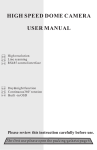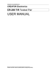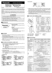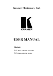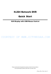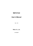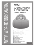
1
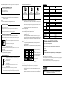
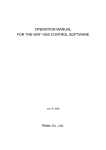
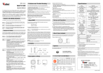
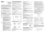
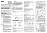
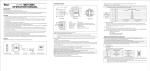
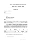
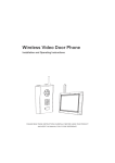
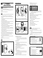
CCD CAMERA
DESCRIPTION OF CAMERA PARTS (Unit:mm)
WAT-902B
⑦SHUTTER switch-The electronic shutter speed conversion switch
Any shutter speed can manually be selected at your request.
The electronic shutter function is set to ON upon shipment.
OPERATION MANUAL
INTRODUCTION:
Thank you for choosing the WAT-902B, B/W CCD Camera.
WATEC hopes that both the quality and design satisfy your requirements.
Before proceeding to install or operate the WAT-902B, please read and understand thoroughly the contents of this
Operation Manual.
For future reference we also advise safe keeping of this manual.
CAUTIONS:
1. Use only the AD-901 or equivalent power adaptor for the WAT-902B. Power supplied without voltage stabilization
and/or the voltage range is not maintained at ±10% 12VD. C. may cause damage to the WAT-902B.
2. Do not expose the WAT-902B to wetness or high moisture conditions. The WAT-902B is designed and approved
for indoor use only.
If the location of the WAT-902B is outdoors or in an outdoor like environment, we recommend that you use an
OUTDOOR CAMERA HOUSING.
3. Avoid the striking of hard objects or dropping the unit.
4. Do not disassemble and/or modify the WAT-902B or the component parts or accessories. WATEC can not be held
responsible for equipment failure or any damage or trouble caused by such action.
5. Do not install the WAT-902B near a heat source, such as radiators or heating air ducts, or in a position subject to
direct sunlight ※, excessive dust, mechanical vibration or shock.
6. When the WAT-902B is used under fluorescent or mercury lighting conditions, a flickering phenomemon may
occur on the monitor screen. This does not mean that the WAT-902B is damaged.
7. When installing the WAT-902B in an industrial or commercial environment (i. e. within equipment housing, near
other electronic device, etc.) make sure to avoid any strong electromagnetic field. Otherwise the video output may
be distorted and monitor sharpness compromised.
8. Check and protect the WAT-902B from any source generating a strong electromagnetic field from your equipment,
when the WAT-902B is fitted near or inside the unit.
9. Do not connect any power supply directly to the VIDEO OUT terminal of the unit. This may cause damage.
10. When a cable operation system such as video/power multiplex transmission is being used, check the specifications
or requirements of your monitor for proper connection to the video signal terminal of the WAT-902B.
11. Do not make connections and/or operate the WAT-902B with wet hands.
12. Should the WAT-902B not work properly, switch off the power and then check that power and video terminals are
properly connected.
※ Sunlight shinning directly onto the camera lens can cause damage to the CCD.
CONTENTS:
Using the contents figures below, check to make sure all parts are present before use.
The WAT-902B parts (complete unit)
Lens cap
WAT-902B
D.C. plug
Iris connector
ON
OFF
FL
(Front)
(Side)
(Rear)
①CCD front face ②Lens mount(CS mount type) ③Hexagonal focusing adjustment screws(3pcs)
④Tripod mounting screw holes(Upper and lower) ⑤AUTO IRIS ⑥VIDEO OUT ⑦SHUTTER switch
⑧POWER
Remove the four screws from
the upper housing cover.
Pull the upper housing cover
upwards.
Symbol Shutter mode selection chart
EIA: 1/60~1/100000
CCIR: 1/50~1/100000
EIA: 1/60
CCIR: 1/50
EIA: 1/100
CCIR: 1/120
NOTE: When the SHUTTER switch is ON, the shutter function is automatically converted to the electronic iris
mode and the shutter speed is determined in combination with the brightness of an object and the iris of
the lens in the range shown on the chart on the left.
⑧POWER-The power input terminal
NOTE: The optional power adaptor AD-901 (DC+12V, 250mA) is recommended for use with the WAT-902B.
⑨BACK LIGHT OFF/ON-The switch for the Back Light compensation function.
NOTE: The switch is set to OFF(upwards) upon shipment.
⑩AGC OFF/ON-The AGC (Auto gain control) operation switch
NOTE: When the switch is set upwards, AGC is ON and when it is set downwards, AGC is OFF.
The switch is set to ON upon shipment.
⑪AGC Lo/Hi-AGC gain switch
The switch is set to Hi gain at the upper position and to Lo gain at the lower position.
The switch is set to Lo upon shipment.
⑫Γ OFF/ON-The gamma ON/OFF selection switch
The switch is ON at the upper position and OFF at the lower position.
The switch is set to ON (upper) upon shipment.
OPERETION:
NOTE: Ensure that before any connections are made to the WAT-902B the power is switched OFF.
1) Remove the Lens Cap from ① the CCD front face and attach the lens.
NOTE: When the C mount type lens is used, mount the optional 30CMA-R, C mount conversion ring before the
lens is mounted.
: Confirm the specifications of the lens to be used, when it can not be mounted onto the WAT-902B smoothly.
(Mounting a nonstandardized lens may cause damage to the threads of the lens and lens mount too.)
2) Using the Auto Iris lens
Connect the iris control cable to AUTO IRIS⑤ on the WAT-902B, when the auto iris lens is used.
①CCD front face (light receiving face of the CCD camera)
NOTE: 1. Handle the CCD and lens with special care.
2. Always attach the lens cap so as to protect the lens and the CCD from contamination and damage.
3. Dirt, water or oil deposits on either will cause an unclear picture on the monitor and scratches will
become permanent damage.
②Lens mount (CS mount type)
NOTE: Any standard model C mount lens can be attached to the WAT-902B, if our optional C mount ring,
30CMA-R is fitted to the unit.
③Hexagonal focusing adjustment screws (for fine focusing adjustment by the lens mount ring.)
There are three hexagonal focusing adjustment screws each placed at intervals of 120°around the lens mount
ring for the forward and backward motion of the lens mount.
④Tripod mounting screw holes (Upper and lower)
Thread size and depth are the same as those for the standard camera tripods.(U1/4”)
⑤AUTO IRIS
Female connector for the auto-iris lens.
NOTE: When the BLC(back light compensation)switch is ON in conjunction with the auto iris lens, the iris
control is shown within the restricted area on the monitor screen. See Sec. 9 of OPERATION in the
operation manual for a more detailed explanation.
⑥VIDEO OUT-The RCA terminal for video signal output.
NOTE: A 3C2V or 5C2V cable with 75Ω impedance must be used for connection with the WAT-902B.
IMPORTANT NOTES FOR AUTO IRIS USAGE
: Ensure that the connector mentioned in the operation manual of the Auto-Iris lens
can be applied to the one shown in the diagram on the right and connect it firmly to
the connector on the right side of the WAT-902B.
: Insert the pins as shown in the picture on the right. If the pin configuration is
different from that shown, use the special adaptor supplied with this unit.
CAUTION: Do not touch the power pin or the signal control pin with the Common
(GND) pins on the extra connector for the Auto Iris lens.
Common (GND)
Signal Control
Common (GND)
Power
Configuration of the Auto Iris lens connector
(on the side of the WAT-902B)
3) Insert the DC plug of the power adaptor to POWER⑧ on the rear pannel of the WAT-902B.
NOTE: Ensure that the power adaptor is not ON before insertion of the DC plug into POWER⑧.
IMPORTANT NOTES FOR POWER ADAPTOR USAGE
: Use a stabilized power adaptor designed for DC+12V±10% with a current
capacity of 250mA.
: Use the optional DC plug when the shape or polarity of the DC plug of the DC
power adaptor can not be fitted to POWER⑧ on the WAT-902B.
: Connect the cables to the DC adaptor using the drawing on the right.
Caution : Be careful not to touch any other terminal while wiring.
NOTE : This may cause damage to the WAT-902B and power adaptor or may cause
fire if the above care and attention are not adhered to.
DC+12V
COMMON (GND)
4) Connect VIDEO OUT⑥ on the WAT-902B to the monitor, using the coaxial cable with 75Ω impedance such as
3C2V or 5C2V.
IMPORTANT NOTES ON THE MONITOR SPECIFICATIONS
: Select a monitor with the same transmissin mode as the WAT-902B.
There are two versions, EIA and CCIR.
: A monitor with 700TV lines is recommended.
Caution: Do not use a monitor which uses a video signal/power multiplex transmission cable.
5) Switch on the WAT-902B, monitor and all other allied equipment.
NOTE: When the picture dose not appear on the monitor screen, switch off all equipment and check for correct
connections to all the appliances.
6) Focusing
Focusing the lens of the WAT-902B is achieved while looking at the monitor screen.
NOTE: In cases when the unit can not be focused manually, use the focusing adjustment method set out below.
IMPORTANT NOTES ON FOCUSING
: Attach the required lens on the WAT-902B and loosen the hexagonal screws③. (3pcs.)
Be extremely careful not to drop the lens.
: Set the focus ring to the infinitive (∞) position, and while looking at the monitor screen, move the lens forwards or
backwards to focus.
: Tighten the hexagonal focusing adjustment screws③, (3pcs.) when focusing is completed.
IMPORTANT NOTES FOR USAGE OF AUTO IRIS LENS
: The optimal picture may not be obtained on the monitor screen due to the different kinds of lenses used which give
different angular views and contrast of objects. In this case adjustment must be made by reading through as shown below.
①Check that the required auto iris lens has the adjustment control as shown in the drawing on
the left.
②Set the ALC(Automatic Level Control) adjustment control in the center between AV and PK
on the lens using a small screw driver.
③Point the lens towards the object while looking at the screen.
Turn the LEVEL adjustment control clockwise or anti-clockwise to obtain the optimal
brightness of the object on the monitor screen.
④Turn the ALC adjustment control towards PK when the contrast of the object needs to be stronger or towards AV when
it needs to be weaker.
⑤Continually repeat the procedures ③ and ④ to obtain an optimal picture.
SPECIFICATIONS:
8) AGC OFF/ON⑩ switch and AGC Lo/Hi⑪ switch
(AGC OFF)
AGC is OFF which represents
10dB at a fixed gain regardless of
the position of AGC Lo/Hi ⑪
switch.
(AGC ON-Lo)
The gain circuit varies in a range
between 5 and 20dB which is
controlled by AGC.
(AGC ON-Hi)
The gain circuit varies in a range
between 5 and 32dB which is
controlled by AGC.
Number of total pixels
811(H)×508(V)
Number of effective pixels
768(H)×494(V)
2:1 Interlace
Scanning system
1Vp-p 75Ω (Unbalanced)
Video output
570TV Lines
Minimum illumination
BLC OFF
BLC ON
The left drawings show differeces in the light
measurement range in the OFF/ON switching
positions.
When the Back Light Compensation ⑨switch
is ON, the central section and all the sections in
the lowest row which are divided into three
sections, are used for the light measurment
against the object monitored.
(The sections of slant lines are light
measurment ranges.)
10) Γ OFF/ON⑫ switch
The WAT-902B is provided with Γ OFF/ON⑨ switch, whitch is very useful for required purposes.
NOTE: Check that the ⑫ switch is ON (upon shipment) for normal use.
: Use the ⑫ switch in the OFF position, when you want to enhance the brightness of a monitored object in a
dark environment.
: Be careful; the monitored picture may not be true due to change of tone characteristics, when the ⑫ switch is
OFF.
0.01 Lux F1.4 (AGC Lo)
0.003 Lux F1.4 (AGC Hi)
50dB (AGC off, Γ=1)
S/N ratio
ON(EI)
OFF
FL
AGC
752(H)×582(V)
8.6μm(H)×8.3μm(V)
Internal
Sync system
Shutter
795(H)×596(V)
8.4μm(H)×9.8μm(V)
Unit cell size
Resolution
NOTE: Check that AGC is in the ON-Lo position (upon shipment) as for normal use.
: Select the AGC OFF position to improve S/N(noise level) in an environment whitch is unnecessary for AGC
control.
: Select the AGC ON-Hi position to enlarge the AGC range by two iris stops when the WAT-902B is used in
a dark environment.
: S/N ratio deteriorates in the AGC ON-Hi position as compared with the AGC ON-Lo position.
9) Back Light Compensation switch ⑨
The WAT-902B is provided with back light compensation function, which is very useful in certain environments.
NOTE: Check that BLC⑨ switch is OFF (upon shipment) as for normal use.
This function restricts the range of the light measured on the monitor screen. when the auto iris lens is used
or SHUTTER⑦ switch is ON.
When Back Light Compensation⑨ switch is OFF, the whole monitored screen area is in use as the light
measurement area as shown in the below and left drawing. When Back Light Compensation⑨ switch is ON,
the central and the lowest parts on the monitored screen area is used for this function as shown below on the
drawing on the right.
Example
If there is bright sunshine or bright ilumination behind the object monitored, the back light compensation
switch should be implemented.
The middle square and lower 3 squares will appear darker and therefore, improve visibility of the monitored
object.
WAT-902B (CCIR)
1/2" Interline transfer CCD image sensor
Pick-up element
7) Select any required shutter speed by changing SHUTTER⑦
EXAMPLE FOR SHUTTER SWITCH USE
ON: When a fixed lens without the iris function is used.
When brightness of an object is continually variable such as continuous monitoring of the
outdoors through a 24 hour cycle.
OFF: When an auto iris lens is used.
When an optimal picture can be obtained on the monitor screen in conditions that light is less
variable such as indoors.
FL: When a flickering phenomenon on the monitor screen is caused by a source such as
fluourescent or mercury lighting.
NOTE: Select the most appropriate function out of the above three that correspond to your required monitoring.
: Smear phenomenon (a portion of an object with high brightness projecting bright trails up and downwards) appears
on the monitor screen, when an object with high brightness is monitored. (especially in the ON position) This dose
not mean the camera is damaged. This is normal.
WAT-902B (EIA)
Model
ON
OFF
Gamma characteristic
Back light compensation
1/60~1/100000 sec.
1/50~1/100000 sec.
1/60 sec.
1/50 sec.
1/100 sec.
1/120 sec.
AGC Lo: 5~20dB, AGC Hi: 5~32dB
OFF: 10dB
Γ≒0.45 (ON), 1.0 (OFF) selectable
ON/OFF selectable
DC +12V±10%
Power supply
135mA
Current
Storage temperature
−30℃∼+70℃
Operating temperature
−10℃∼+40℃
Approx. 90g
Weight
This device complies with Part 15 of the FCC Rules.
Operation is subject to the following two conditions:
(1)This device may not cause harmful interference,and
(2)this device must accept any interference received,including interference that may cause undesired
operation.
Important:
The camera mentioned above does not comply with this regulation, if it is modified at your disposal.
Design and specifications are subject to change without notice.
WATEC is not responsible for any inconvenience or the attendant damages to the video, audio and monitoring recording equipment,
caused by misuse, misoperation or inproper wiring of our equipment.
If for any reason the WAT-902B does not work properly, or if you have any questions regarding installation or operation,
please contact the distributor or dealer from which it was purchased.
Watec Co.,Ltd. Address : 254-2, Nihonkoku, Daihoji, Tsuruoka-Shi, Yamagata-Ken, 997-0017 JAPAN.
Phone : +81-235-23-4400
Fax : +81-235-23-4409