1
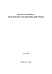
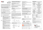
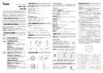
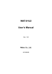
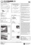
Wide Dynamic Range Camera
Problems and Trouble Shooting
If any of the following problems occur when using the WAT-233,
WAT-233
• An optimal picture cannot be obtained, after checking that all the cables and
connections are correctly in place
• Smoke or any unusual odor emerges from the WAT-233
③FINE FOCUS ADJUSTMENT SCREWS
・There are 3 hex. adjustment screws each placed at intervals of 120゜for fine
focusing of the lens.
④AUTO-IRIS SOCKET
・This socket is for the video/DC auto-iris lens cable connector.
(Video/DC: Auto selected by the camera)
• An object becomes embedded or a quantity of liquid seeps into the camera
housing
⑤TRIPOD MOUNTING SCREW HOLES
・Mounting holes for stands. The size of these threads are 1/4”, 20 threads, 4.5
±0.2mm, which is the same as any standard camera tripod (U1/4”).
This Operation Manual covers safety, camera functions, installation and the
correct operating procedure for the WAT-233. First, we ask you to read this
Operation Manual thoroughly, then install and operate the WAT-233 as advised.
In addition, for future reference, we also advise safekeeping of this manual.
• More than the recommended voltage or/and amperage has been applied
to the WAT-233 by mistake
⑥VIDEO OUT (BNC)
・The terminal for composite video signal output
• Anything unusual occurring to any equipment connected to the WAT-233
Please contact the distributor or dealer from which the WAT-233 was purchased,
if you do not understand the installation, operation or safety instructions laid out
in this manual. Not understanding the contents of the Operation Manual
sufficiently may cause damage to the camera.
Disconnect the camera immediately according to the following procedures:
⑦I/O CONNECTOR
・The control terminal for the RS-232, ALARM and infrared cut filter changer.
Operation Manual
①Switch off the main power supply to the camera.
②Remove the power and video cables connected to the WAT-233.
③Contact the distributor or dealer from which the WAT-233 was purchased.
Guide to the Safety Symbols
The definitions of the symbols used in this operation manual are:
Danger
Warning
Caution
When you do not adhere to or take notice of the “Danger” sign, it
may lead to a serious accident such as death or injury caused by
fire or electric shock.
About EMC
The WAT-233 is in conformity with EMC test standards carried out by authorized
organizations in Japan.
When you do not adhere to or take notice of the “Warning” sign, it
may cause severe damage such as a physical injury.
When you do not adhere to or take notice of the “Caution” sign, it
may incur injury and cause damage to peripheral objects in the
immediate surroundings.
NTSC
FCC Part15 class B
PAL
EN61000-6-3/EN50130-4
※Please use an auxiliary power supply (eg: UPS) to this camera to comply with
EN50130-4 of EMC standards.
Danger
Do not modify the WAT-233. A modified camera may not conform
to EMC test standards.
Cautions for Safety
The WAT-233 is designed to be used safely; however, if not used safely, it may
lead to a physical accident caused by fire and electric shock. Therefore, please
keep and read the “Cautions for safety” below for protection against accidents.
Danger
Warning
Caution
⑩OSD(On Screen Display) CONNECTOR
・The terminal designed for connection with the remote control for setting
the functions on the screen.
⑪OPERATION BUTTON
・The operation button for setting the functions on the screen.
Power Supply
Use a stabilized power adaptor designed for DC+12V±10%, with a current
capacity of more than 250mA.
Use the optional DC plug if the shape or polarity of the DC plug of the power
adaptor to be used is not compatible with the camera (See the drawing on the
right below).
Warning
Using the contents figures below, check to make sure all parts are present before
use.
• Do not operate the WAT-233 with wet hands.
Caution
④
• Avoid the striking of hard objects or dropping the WAT-233.
Manual Lens
Adjust the focus and iris to the best position
on the lens.
Video Auto-iris Lens
Adjust the focus on the lens/camera, then
adjust the focus on the lens. .
DC Auto-iris Lens
Adjust the iris level on the camera, then adjust
the focus on the lens.
※When using a DC Auto-Iris lens, adjustments to the iris level can be done
by changing the level in the OSD menu by use of the remote control
(RC-01) included. Please refer to the User’s Manual.
8) When detailed settings are required or an adequate image is not
obtained, connect the remote control(RC-01) to ⑩OSD(On Screen
Display) CONNECTOR, then set the functions on the screen by
⑪OPERATION BUTTON.
9) When controlling the RS-485, alarm output and infrared cut-filter
changer, connect to ⑦I/O CONNECTOR after wiring using the attached
cable. See the pin configuration as follows.
COMMON(GND)
Before connecting the auto-iris lens, please make sure that the pin configuration
is correct by confirming with the following table. If the configuration of your iris
connector is different from the following, the plug and pins will need to be
rewired.
Description of Parts
7) After following the procedure below and the picture is still out of focus, open
the iris fully and loosen ③FINE FOCUS ADJUSTMENT SCREWS with the
hex. wrench and move the lens forwards until a clear picture is obtained.
DC+12V
The wiring of the connector must be exact.
Be careful not to touch the other terminal while wiring.
Protect the wiring portion by using insulation tape after
wiring. If the above care and attention is not adhered to,
damage to the WAT-233 and power adaptor may occur and
may also cause fire.
Auto-iris Lens
• Use a stabilized power adaptor designed for DC+12V±
±10%,
The WAT-233 uses high quality electrical parts and precision
components.
• Do not connect any power supply directly to the video out
terminal of the unit.
Do not connect the WAT-233 with any monitor using a video/power
single transmission terminal. The WAT-233 is not designed for use
with this type of equipment. We also advise you to read the
operation manual of the monitor you plan to use before any
connections are made.
• Do not install the WAT-233 in a position subject to direct
sunlight.
Sunlight shinning directly onto the WAT-233 lens can cause
damage to the CCD.
• Select a stable place for installation of the WAT-233.
Use a support of durable strength around an installation position
on a ceiling or wall when a camera stand or tripod is used.
• Do not move the WAT-233 with the cables connected.
Before moving the WAT-233, always remove the video cable and
power cable from the rear of the camera first.
• Avoid using the WAT-233 near any strong electromagnetic field.
After installing into main equipment, if the WAT-233 is exposed to
electromagnetic waves causing the monitored image to become
distorted, we recommend the camera be shielded by appropriate
protective casing.
⑨POWER IN
・The terminal designed for connection with the DC-plug of the power adaptor.
Contents
• Do not disassemble and/or modify the WAT-233.
with a current capacity of more than 250mA for the WAT-233.
The recommended voltage is DC+12V±10%
• Do not expose the WAT-233 to wetness or high moisture
conditions.
The WAT-233 is designed and approved for indoor use only. The
WAT-233 is not water-resistant or waterproof. If the location of the
camera is outdoors or in an outdoor like environment, we
recommend that you use an outdoor camera housing.
• Protect the WAT-233 from condensation.
Keep the WAT-233 dry at all times during storage and operation.
• Should the camera not work properly, switch off the power
immediately. Then check the camera according to the “Problems
and Trouble shooting” section.
⑧Y/C OUT
・The terminal for Y/C signal output.
4) Connect ⑥VIDEO OUT on the WAT-233 with the monitor, using a
coaxial cable with 75Ω impedance, such as an RG-59 or an RG-6/U.
If the monitor has an S-terminal, high resolution imaging is possible by
connecting with ⑧Y/C OUT.
※The ⑧Y/C OUT can be used together with the ⑥VIDEO OUT.
※Select a monitor with the same television system as the WAT-233 NTSC or
PAL. A monitor with more than 700TV lines is recommended.
5) Insert the power plug of the power adaptor into ⑨POWER IN on the
back panel of the WAT-233. Confirm that the power adaptor is not connected
to the power supply before insertion of the power plug into ⑨POWER IN.
6) Turn on the power to the WAT-233, monitor and all other allied
equipment. When a picture cannot be obtained on the monitor, or a problem
occurs, check and follow the procedure mentioned in the【Problems and
Trouble Shooting】section.
③
②
①
Pin No.
EIAJ Video
Auto-iris Lens
Arrangement
①
Power
EIAJ DC
Auto-iris Lens
Arrangement
Control
-
Cable
color
Title
A1
Green
D/N EXT CTL(+)
B1
Green/
White
D/N EXT CTL(-)
A2
Purple
D/N STATE OUT(1)
B2
Purple/
White
D/N STATE OUT(2)
A3
Orange
ALARM (1)
B3
Orange/
White
ALARM (2)
②
Not used
③
Iris signals
Drive +
A4
-
NC
④
Common (GND)
Drive -
B4
Black
GND
Control
+
PIN
No.
Mechanical Back
Mechanical Back(M.B) is the projection
from the lens mount to the camera.
Use a lens with a mechanical back that
is less than 5.0mm to the WAT-233.
Set-up and Operation
①IMAGE SENSOR FRONT FACE
・The light receiving face of the image sensor
(Dirt, water or oil deposits on the image sensor will cause an unclear picture on
the monitor. Attach the lens cap to protect the lens and the CCD from
contamination and damage.)
1) Ensure that the power to the WAT-233 and the peripheral equipment is
turned off before making any connections.
2) Remove the lens mount cap from the WAT-233 and attach the CSmount lens. Use the optional C-mount adaptor (34CMA-R) when a C-mount
lens is used.
②LENS MOUNT
・Mount for the lens (CS-mount)
3) Connect the iris control cable to ④AUTO-IRIS SOCKET on the WAT233 when an auto-iris lens is being used.
Function
DAY/NIGHT external control
(Photo coupler input, Polar)
DAY/NIGHT state output
(Photo MOS relay output, Nonpolar)
Motion detection alarm out
(Photo MOS relay output, Nonpolar)
-
A5
Gray
RXD (+)
B5
Gray/
White
RXD (-)
Camera GND
RS-485
(non-isolated)
Data input
from the camera side
Data input
from the camera side
■External DAY/NIGHT control terminal
When EXT mode DAY/NIGHT image setting is selected, the camera mode can
be changed from DAY to NIGHT (IR-cut filter removed) by an applied voltage of 3
to 12V between the terminals A1 and B1 (current value: 1mA at 3V and 6mA at
12V). By connecting a light sensor as indicated in the diagram below,
DAY/NIGHT modes can be controlled according to the lighting condition of the
monitored object. Please make sure the electrical polarity is correct when
connecting the cables.
A1(Green)
+
Light sensor
B1(Green/White)
-
AC adaptor
■DAY/NIGHT status output terminal
When in NIGHT mode (IR-cut filter removed), the terminals A2 and B2 are closed
circuit, therefore, the IR projector system is turned on if it is attached as the
diagram indicated below. Please make sure that the attached IR projector
system supply voltage is 16V or less and the output current is 250mA or less.
Specifications
Model
WAT-233 (NTSC)
Pick-up Element
Number of Total Pixels
Number of
Effective Pixels
Unit Cell Size
IR projector system
1028(H)×508(V)
1028(H)×596(V)
976(H)×494(V)
976(H)×582(V)
5.0μm(H)×7.4μm(V)
Sync. System
A2(Purple)
Video
Output
Composite Video, 1.0 V(p-p), 75Ω (Unbalanced)
Y/C
Y: 1.0 V(p-p), C: 0.3 V(p-p) 75Ω
More than 650TVL (Center)
Color
Minimum
Illumination
Monochrome
■Alarm output terminal
When the motion detection function is selected, the alarm output terminals, A3
and B3, are closed circuit by detecting any movement in the monitored area. If an
alarm is attached as the diagram indicated below, the alerting system (sound,
light, etc.) turns on by the closed circuit. Please make sure that the attached
alarm supply voltage is 16V or less between the 2 terminals and the output
current 250mA or less.
AC adaptor
B3(Orange/White)
※When connecting to the induced load(relay, motor) or incandescent electric
lamp, take measures against surge voltage and inrushing current on the
outside circuit.
■RS485 Communication
OSD operation is possible through the use of the RS485 communication line and
a PC or Pelco-D protocol compatible DVR, Controller, etc… (refer to diagram
below).
The voltage levels between the input terminals A5(RXD[+]) and B5(RXD[-]) must
be between -7 to +12V. Please take caution to connect the input terminals with
the correct polarity. Please refer to the user’s manual for the RS485 compatible
equipment for proper connection and use.
A5 (Gray)
Resistance→
120Ω
RS485
compatible
equipment
B5 (Gray/White)
※The Camera does not have a termination resistor, therefore, as needed,
please terminate the connection on the cable side (Termination Resistor
120Ohms)
0.0006 lx F1.2 (AGC=ON, Shutter=x16, NR=ON, γ=0.45)
0.0005 lx. F1.2 (AGC=ON, Shutter=OFF, NR=ON, γ=0.45)
0.00003 lx. F1.2 (AGC=ON, Shutter=x16, NR=ON, γ=0.45)
x2, x4, x8, x16, x32, x64, x128, x256 (field)
Fixed
AE Mode
1/60, 1/100 sec.
1/50, 1/120 sec.
1/250, 1/500, 1/1000, 1/2000, 1/4000, 1/10000 sec.
AGC
A3(Orange)
0.01 lx F1.2 (AGC=ON, Shutter=OFF, NR=ON, γ=0.45)
More than 50dB (AGC=2dB, γ=1.0)
S/N
EI
Alerting system
2:1 Interlace
Composite
Resolution
B2(Purple/White)
5.0μm(H)×6.25μm(V)
Internal
Scanning System
AC adaptor
WAT-233 (PAL)
1/3 inch 960H interline transfer CCD image sensor
1/60 - 1/100000 sec.
1/50 - 1/100000 sec.
x16 - 1/100000 sec.
HI: 2~44dB / LO: 2~32dB
MGC
2~44dB (1dB step)
Gamma Characteristics
9 steps setting (1.0/0.8/0.7/0.6/0.55/0.5/0.45/0.4/0.35)
White Balance
ATW, PWB, MWB, PRESET (4 types)
Day/Night
Auto (Level selectable) / Manual / External
Wide dynamic range
ON (Level selectable) / OFF
Noise reduction
3DNR ON (Level selectable) / OFF
Lens-iris
Back Light
Compensation
HSBLC(Highlight BLC)
Video / DC
Digital zoom
x2 - x256 (ZOOM / PAN / TILT)
Mirror Image
V-FLIP / H-FLIP / HV-FLIP
ON / OFF
ON / OFF
White blemish correction
Up to 64 pixels
Function settings/Serial port
OSD (On Screen Display) / RS-485 (Pelco-D)
Power Supply
DC+12V±10%
Electric Power
1.62W (135mA)
Operating Temperature
-10 - +50℃
Operating Humidity
Less than 95% RH (Without condensation)
Storage Temperature
-30 - +70℃
Storage Humidity
Less than 95% RH (Without condensation)
Lens Mount
CS-mount (Back focus adjustable)
Size
Weight
43.5(W)×44(H)×67(D) (mm)
Approx. 150g
• Design and specifications are subject to change without notice.
• Watec is not responsible for any inconvenience or the attendant damages
to the video and monitoring recording equipment caused by misuse, misoperation or improper wiring of our equipment.
• If for any reason the WAT-233 does not work properly, or if you have any
questions regarding installation or operation, please contact the distributor or
dealer from which it was purchased.
• For details, please refer to the OSD Manual and H/W Manual available at
http://www.watec.co.jp/english/SoloPages/wat-233.
关于电子信息产品污染控制标识
Contact information
Watec Co., Ltd.
254-2 Nihonkoku, Daihoji, Tsuruoka- Shi,
Yamagata-Ken, 997-0017 Japan
TEL:
+81-235-23-4400 FAX: +81-235-23-4409
Email: [email protected]
URL:
http://www.watec.co.jp
Add.:
1573Z00-Y2000002