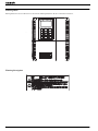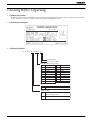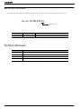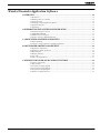
1
Cat. No. I212E-EN-01A Version: Torque Control with Diameter Sensor Model: 3G3RX CX-Drive Version: 2.8.0.16 Notice: OMRON products are manufactured for use according to proper procedures by a qualified operator and only for the purposes described in this manual. The following conventions are used to indicate and classify precautions in this manual. Always heed the information provided with them. Failure to heed precautions can result in injury to people or damage to property. OMRON Product References All OMRON products are capitalized in this manual. The word “Unit” is also capitalized when it refers to an OMRON product, regardless of whether or not it appears in the proper name of the product. OMRON, 2013 All rights reserved. No part of this publication may be reproduced, stored in a retrieval system, or transmitted, in any form, or by any means, mechanical, electronic, photocopying, recording, or otherwise, without the prior written permission of OMRON. No patent liability is assumed with respect to the use of the information contained herein. Moreover, because OMRON is constantly striving to improve its high-quality products, the information contained in this manual is subject to change without notice. Every precaution has been taken in the preparation of this manual. Nevertheless, OMRON assumes no responsibility for errors or omissions. Neither is any liability assumed for damages resulting from the use of the information contained in this publication. Winder/Unwinder Application Software Read and Understand this Manual Please read and understand this manual before using the product. Please consult your OMRON representative if you have any questions or comments. Warranty and Limitations of Liability WARRANTY OMRON's exclusive warranty is that the products are free from defects in materials and workmanship for a period of one year (or other period if specified) from date of sale by OMRON. OMRON MAKES NO WARRANTY OR REPRESENTATION, EXPRESS OR IMPLIED, REGARDING NON-INFRINGEMENT, MERCHANTABILITY, OR FITNESS FOR PARTICULAR PURPOSE OF THE PRODUCTS. ANY BUYER OR USER ACKNOWLEDGES THAT THE BUYER OR USER ALONE HAS DETERMINED THAT THE PRODUCTS WILL SUITABLY MEET THE REQUIREMENTS OF THEIR INTENDED USE. OMRON DISCLAIMS ALL OTHER WARRANTIES, EXPRESS OR IMPLIED. LIMITATIONS OF LIABILITY OMRON SHALL NOT BE RESPONSIBLE FOR SPECIAL, INDIRECT, OR CONSEQUENTIAL DAMAGES, LOSS OF PROFITS OR COMMERCIAL LOSS IN ANY WAY CONNECTED WITH THE PRODUCTS, WHETHER SUCH CLAIM IS BASED ON CONTRACT, WARRANTY, NEGLIGENCE, OR STRICT LIABILITY. In no event shall the responsibility of OMRON for any act exceed the individual price of the product on which liability is asserted. IN NO EVENT SHALL OMRON BE RESPONSIBLE FOR WARRANTY, REPAIR, OR OTHER CLAIMS REGARDING THE PRODUCTS UNLESS OMRON'S ANALYSIS CONFIRMS THAT THE PRODUCTS WERE PROPERLY HANDLED, STORED, INSTALLED, AND MAINTAINED AND NOT SUBJECT TO CONTAMINATION, ABUSE, MISUSE, OR INAPPROPRIATE MODIFICATION OR REPAIR. Winder/Unwinder Application Software 1 Application Considerations SUITABILITY FOR USE OMRON shall not be responsible for conformity with any standards, codes, or regulations that apply to the combination of products in the customer's application or use of the products. At the customer's request, OMRON will provide applicable third party certification documents identifying ratings and limitations of use that apply to the products. This information by itself is not sufficient for a complete determination of the suitability of the products in combination with the end product, machine, system, or other application or use. The following are some examples of applications for which particular attention must be given. This is not intended to be an exhaustive list of all possible uses of the products, nor is it intended to imply that the uses listed may be suitable for the products: • Outdoor use, uses involving potential chemical contamination or electrical interference, or conditions or uses not described in this manual. • Nuclear energy control systems, combustion systems, railroad systems, aviation systems, medical equipment, amusement machines, vehicles, safety equipment, and installations subject to separate industry or government regulations. • Systems, machines, and equipment that could present a risk to life or property. Please know and observe all prohibitions of use applicable to the products. NEVER USE THE PRODUCTS FOR AN APPLICATION INVOLVING SERIOUS RISK TO LIFE OR PROPERTY WITHOUT ENSURING THAT THE SYSTEM AS A WHOLE HAS BEEN DESIGNED TO ADDRESS THE RISKS, AND THAT THE OMRON PRODUCTS ARE PROPERLY RATED AND INSTALLED FOR THE INTENDED USE WITHIN THE OVERALL EQUIPMENT OR SYSTEM. PROGRAMMABLE PRODUCTS OMRON shall not be responsible for the user's programming of a programmable product, or any consequence thereof. 2 Winder/Unwinder Application Software Disclaimers CHANGE IN SPECIFICATIONS Product specifications and accessories may be changed at any time based on improvements and other reasons. It is our practice to change model numbers when published ratings or features are changed, or when significant construction changes are made. However, some specifications of the products may be changed without any notice. When in doubt, special model numbers may be assigned to fix or establish key specifications for your application on your request. Please consult with your OMRON representative at any time to confirm actual specifications of purchased products. DIMENSIONS AND WEIGHTS Dimensions and weights are nominal and are not to be used for manufacturing purposes, even when tolerances are shown. PERFORMANCE DATA Performance data given in this manual is provided as a guide for the user in determining suitability and does not constitute a warranty. It may represent the result of OMRON's test conditions, and the users must correlate it to actual application requirements. Actual performance is subject to the OMRON Warranty and Limitations of Liability. ERRORS AND OMISSIONS The information in this manual has been carefully checked and is believed to be accurate; however, no responsibility is assumed for clerical, typographical, or proofreading errors, or omissions. Winder/Unwinder Application Software 3 Safety Precautions • Indications and meanings of safety information In this user's manual, the following precautions and signal words are used to provide information to ensure the safe use of the RX Inverter. The information provided here is vital to safety. Strictly observe the precautions provided. • Meanings of signal words DANGER Indicates an imminently hazardous situation which, if not avoided, is likely to result in serious injury or may result in death. Additionally there may be severe property damage. CAUTION Indicates a potentially hazardous situation which, if not avoided, may result in minor or moderate injury or in property damage. • Alert symbols in this document DANGER Turn off the power supply and implement wiring correctly. Not doing so may result in a serious injury due to an electric shock. Wiring work must be carried out only by qualified personnel. Not doing so may result in a serious injury due to an electric shock. Do not change wiring and slide switches (SW1), put on or take off Digital Operator and optional devices, replace cooling fans while the input power is being supplied. Doing so may result in a serious injury due to an electric shock. Be sure to ground the unit. Not doing so may result in a serious injury due to an electric shock or fire. (200-V class: type-D grounding, 400-V class: type-C grounding) Do not remove the terminal block cover during the power supply and 10 minutes after the power shutoff. Doing so may result in a serious injury due to an electric shock. Do not operate the Digital Operator or switches with wet hands. Doing so may result in a serious injury due to an electric shock. Inspection of the Inverter must be conducted after the power supply has been turned off. Not doing so may result in a serious injury due to an electric shock. The main power supply is not necessarily shut off even if the emergency shutoff function is activated. 4 Winder/Unwinder Application Software CAUTION Do not connect resistors to the terminals (PD/+1, P/+, N/-) directly. Doing so might result in a small-scale fire, heat generation or damage to the unit. Install a stop motion device to ensure safety. Not doing so might result in a minor injury. (A holding brake is not a stop motion device designed to ensure safety.) Be sure to use a specified type of braking resistor/regenerative braking unit. In case of a braking resistor, install a thermal relay that monitors the temperature of the resistor. Not doing so might result in a moderate burn due to the heat generated in the braking resistor/regenerative braking unit. Configure a sequence that enables the Inverter power to turn off when unusual overheating is detected in the braking resistor/ regenerative braking unit. The Inverter has high voltage parts inside which, if short-circuited, might cause damage to itself or other property. Place covers on the openings or take other precautions to make sure that no metal objects such as cutting bits or lead wire scraps go inside when installing and wiring. Do not touch the Inverter fins, braking resistors and the motor, which become too hot during the power supply and for some time after the power shutoff. Doing so may result in a burn. Take safety precautions such as setting up a molded-case circuit breaker (MCCB) that matches the Inverter capacity on the power supply side. Not doing so might result in damage to property due to the short circuit of the load. Do not dismantle, repair or modify this product. Doing so may result in an injury. Winder/Unwinder Application Software 5 Precautions for Safe Use • Installation and storage Do not store or use the product in the following places. •Locations subject to direct sunlight. •Locations subject to ambient temperature exceeding the specifications. •Locations subject to relative humidity exceeding the specifications. •Locations subject to condensation due to severe temperature fluctuations. •Locations subject to corrosive or flammable gases. •Locations subject to exposure to combustibles. •Locations subject to dust (especially iron dust) or salts. •Locations subject to exposure to water, oil, or chemicals. •Locations subject to shock or vibration. • Transporting, installation and wiring •Do not drop or apply strong impact on the product. Doing so may result in damaged parts or malfunction. •Do not hold by the front cover and terminal block cover, but hold by the fins during transportation. •Do not connect an AC power supply voltage to the control input/output terminals. Doing so may result in damage to the product. •Be sure to tighten the screws on the terminal block securely. Wiring work must be done after installing the unit body. •Do not connect any load other than a three-phase inductive motor to the U, V, and W output terminals. •Take sufficient shielding measures when using the product in the following locations. Not doing so may result in damage to the product. Locations subject to static electricity or other forms of noise. Locations subject to strong magnetic fields. Locations close to power lines. • Operation and adjustment •Be sure to confirm the permissible range of motors and machines before operation because the inverter speed can be changed easily from low to high. •Provide a separate holding brake if necessary. •If the Drive Programming stops during multi-function output, the output status is held. Take safety precautions such as stopping peripheral devices. •If the clock command is used in Drive Programming, an unexpected operation may occur due to weak battery. Take measures such as detecting a weak battery by a check that the clock data returns to the initial setting and stopping the inverter or programs. When the LCD Digital Operator is removed or disconnected, Drive Programming is in a waiting status by the clock command. • Maintenance and Inspection •Be sure to confirm safety before conducting maintenance, inspection or parts replacement. •The capacitor service life is influenced by the ambient temperature. Refer to “Smoothing Capacitor Life Curve” described in the manual. When a capacitor reaches the end of its service life and does not work as the product, you need to replace the capacitor. •When disposing of LCD digital operators and wasted batteries, follow the applicable ordinances of your local government. When disposing of the battery, insulate it using tape. The following display must be indicated when products using lithium primary batteries (with more than 6 ppb of perchlorate) are transport to or through the State of California, USA. Perchlorate Material - special handling may apply. See www.dtsc.ca.gov/hazardouswaste/perchlorate The 3G3AX-OP05 has the lithium primary battery (with more than 6 ppb of perchlorate). Label or mark the above display on the exterior of all outer shipping packages of your products when exporting your products which the 3G3AX-OP05 are installed to the State of California, USA. 6 Winder/Unwinder Application Software •Do not short + and –, charge, disassemble, heat, put into the fire, or apply strong impact on the battery. The battery may leak, explode, produce heat or fire. Never use the battery which was applied strong impact due to such as fall on the floor, it may leak. •UL standards establish that the battery shall be replaced by an expert engineer. The expert engineer must be in charge of the replacement and also replace the battery according to the method described in this manual. •When the display of LCD Digital Operator can not be recognized due to the service life, replace the LCD Digital Operator. Precautions for Correct Use • Installation •Mount the product vertically on a wall with the product's longer sides upright. The material of the wall has to be noninflammable such as a metal plate. • Main circuit power supply •Confirm that the rated input voltage of the Inverter is the same as AC power supply voltage. • Error Retry Function •Do not come close to the machine when using the error retry function because the machine may abruptly start when stopped by an alarm. •Be sure to confirm the RUN signal is turned off before resetting the alarm because the machine may abruptly start. • Non-stop function at momentary power interruption •Do not come close to the machine when selecting restart in the non-stop function at momentary power interruption selection (b050) because the machine may abruptly start after the power is turned on. • Operation stop command •Provide a separate emergency stop switch because the STOP key on the Digital Operator is valid only when function settings are performed. •When checking a signal during the power supply and the voltage is erroneously applied to the control input terminals, the motor may start abruptly. Be sure to confirm safety before checking a signal. • Product Disposal •Comply with the local ordinance and regulations when disposing of the product. Winder/Unwinder Application Software 7 Warning labels Warning labels are located on the inverter as shown in the following illustration. Be sure to follow the instructions. :$51,1* /2&$/ 5(027( 5($' :5,7( (6& ):' 5(9 Warning description 8 Winder/Unwinder Application Software Checking Before Unpacking • Checking the product •On delivery, be sure to check that the delivered product is the Inverter RX model that you ordered. Should you find any problems with the product, immediately contact your nearest local sales representative or OMRON sales office. • Checking the nameplate 3G3RX-A2004-E1F 1(;;; • Checking the model 3 G 3 R X -A 2 0 5 5 - E F F: Built-in filter E: Europe standard Max. applicable motor capacity 004 007 015 022 037 040 055 075 110 150 0.4 kW 0.75 kW 1.5 kW 2.2 kW 3.7 kW 4.0 kW 5.5 kW 7.5 kW 11 kW 15 kW 185 220 300 370 450 550 750 900 11K 13K 18.5 kW 22 kW 30 kW 37 kW 45 kW 55 kW 75 kW 90 kW 110 kW 132 kW Voltage class 2 4 3-phase 200 V AC (200-V class) 3-phase 400 V AC (400-V class) Enclosure rating Winder/Unwinder Application Software A Panel-mounting (IP20 min.) or closed wall-mounting models B IP00 9 Revision History •A manual revision code appears as a suffix to the catalogue number located at the lower left of the front and back covers. Cat. No. I212E-EN-01 Revision code Revision code Revision date 01 November 2013 Description Original production Related Manuals Cat. No. I560-E2 I130E-EN 10 Description RX User’s Manual RX Quick Start Guide I579-E2 LCD Digital Operator User’s Manual I580-E2 MX2/RX/LX Drive Programming User’s Manual Winder/Unwinder Application Software Winder/Unwinder Application Software 1 OVERVIEW.............................................................................................................13 1.1 Introduction ..................................................................................................................................................... 13 1.2 Handling of this user’s manual........................................................................................................................ 13 1.3 Safety instruction............................................................................................................................................. 13 1.4 Advantages using the application software..................................................................................................... 14 1.5 Application diagram........................................................................................................................................ 15 1.6 Terminology ..................................................................................................................................................... 15 2 PREPARATION AND SYSTEM CONFIGURATION ................................................16 2.1 Installation and power circuits........................................................................................................................ 16 2.2 3G3RX DIP-SWITCH..................................................................................................................................... 16 2.3 3G3RX connection diagram............................................................................................................................ 17 2.4 Encoder connection (3G3AX-PG Board) ....................................................................................................... 18 3 APPLICATION CONFIGURATION STEPS .............................................................19 3.1 Motor autotuning ............................................................................................................................................ 19 3.2 Parameter settings and Drive Programming application .............................................................................. 21 4 DRIVE PROGRAMMING PARAMETERS...............................................................28 4.1 Application configuration................................................................................................................................ 28 4.2 Application software parameters .................................................................................................................... 29 4.3 Inputs/outputs.................................................................................................................................................. 30 4.4 Monitor parameters......................................................................................................................................... 30 4.5 Error codes ....................................................................................................................................................... 31 4.6 Other relevant parameters .............................................................................................................................. 31 5 WINDER/UNWINDER APPLICATION FUNCTIONS.............................................32 5.1 Friction compensation..................................................................................................................................... 32 5.2 Taper function ................................................................................................................................................. 33 5.3 Preset function timing diagram ...................................................................................................................... 34 5.4 Freeze function timing diagram...................................................................................................................... 35 5.5 Reset function timing diagram........................................................................................................................ 36 5.6 Diameter completion function ........................................................................................................................ 37 Winder/Unwinder Application Software 11 12 Winder/Unwinder Application Software Winder/Unwinder Application Software 1 OVERVIEW 1.1 Introduction This user’s manual explains how to use the Winder/Unwinder Application program for 3G3RX inverter. Be sure to read this user’s manual carefully before using this Winder/Unwinder Application program, and keep it on hand for further reference. Note: In this specific Winder/Unwinder Application program, the tension set point is given through the analog input O and the diameter sensor through the analog input O2. Winder Line Speed Reference is forced internally in the firmware. It is needed to do a soft line acceleration ramp during winding/unwinding procedure. 1.2 Handling of this user’s manual The contents of this user’s manual are subject to change without prior notice. No part of this user’s manual may be reproduced in any form without the publisher’s permission. If you find any incorrect description, missing description or have questions concerning the contents of this user’s manual, please contact the publisher. 1.3 Safety instruction Be sure to read this user’s manual, inverter user’s manual, and appended documents thoroughly before using Winder/Unwinder Application program and the inverter. Ensure you to understand and follow all safety information, precautions, and operating and handling instructions for the correct use of the inverter. Always use the inverter strictly within the range of specifications described in the inverter user’s manual and correctly implement maintenance and inspection to prevent fault from occurring. When using the inverter together with optional products, also read the manual of those products. Note that this user’s manual and the manual for each optional product to be used should be delivered to the end user of the inverter. In this user’s manual you can find WARNING along the instruction WARNINGS: indicates that incorrect handling may cause hazardous situation, which may result in serious personal injury or death. Winder/Unwinder Application Software 13 Winder/Unwinder Application Software 1.4 Advantages using the application software Functions supported in this application software: Control mode • In this specific application case software, winder torque is controlled by RX standard torque control. Diameter sensor/calculation • A sensor for diameter measurement is needed. • Diameter reset, preset and freeze functionality. Tension profile/taper function • 3-point tension profile to decrease tension by growing diameter. Special digital output functions • Winding job finished (job completion). Other features • • • • • 14 Change between winder and unwinder by digital input. Line speeds up to 600m/min supported. Static friction compensation. Dynamic friction compensation. Diameter monitor. Winder/Unwinder Application Software OVERVIEW 1.5 Application diagram Reel Diameter in mm - [P100] Maximum Line Speed - [P101] Diameter Sensor - [O2 Terminal] Build Up Ratio Preset Value - [P103] Diameter Preset Function - [X(01)] Diameter Calculation Diameter Freeze Function - [X(02)] Diameter Build Up Ratio - [P130] Diameter in mm - [P124] Diameter Reset Function - [X(03)] Winder Drive Speed Limit Speed Offset - [P111] Maximum Build Up Ratio - [P107] Build Up Ratio - [P130] Torque Tension Reference - [P119] Tension Reference - [O Terminal] Taper Middle Build Up Ratio - [P106] Taper Taper Tension@Minimum BUR - [P108] Static Friction Compensation - [P115] Taper Tension@Middle BUR - [P109] Dynamic Friction Compensation - [P114] Friction Compensation Torque Drive Reference - [P037] Taper Tension@Maximum BUR - [P110] 1.6 Terminology Concept Build Up Ratio (BUR) Description Is the ratio between reel diameter and maximum diameter, considering for reel diameter the value 1. For instance, an application in which reel diameter is 90mm and maximum diameter is 900mm, the ratio is 10, so: BUR = (maximum diameter/reel diameter) = 900mm/90mm = 10 Note: In this application software the Build Up Ratio is scaled by 1000. So, in the last example, the minimum build up ratio (reel diameter) used internally is 1000 (= 1 * 1000) and for the maximum diameter we will use 10000 (= 10 * 1000). It is needed to multiply by 1000 the calculated Build Up Ratio (BUR). Winder/Unwinder Application Software 15 Winder/Unwinder Application Software 2 PREPARATION AND SYSTEM CONFIGURATION To prepare the inverters for operation, the configuration tool CX-Drive is used for setting parameters and to download the Winder/Unwinder Application program. In the following chapters we will show the necessary steps to set up the inverter for a winder/unwinder application. We will use 3G3RX inverter. 2.1 Installation and power circuits This manual does not cover how to install the inverters in cabinets, how to wire power supply or how to satisfy other application specific requirements. Please, refer to the RX User’s Manual (I560-E2). 2.2 3G3RX DIP-SWITCH There is only one switch in 3G3RX. If the switch is ON, digital input 1 and 3 are configured as emergency shutoff inputs. Factory setting is OFF, so just check that the switch is really OFF. Slide switch SW1 ON Slide lever (factory deffault: OFF) OFF 16 ON Winder/Unwinder Application Software PREPARATION AND SYSTEM CONFIGURATION 2.3 3G3RX connection diagram Braking resistor (optional) DC reactor (optional) PD/+1 R/L1 3-phase 200 V AC 3-phase 400 V AC To wire the control circuit power supply and main circuit power supply separately, be sure to remove the J51 connector wire first. N/– RB U/T1 S/L2 V/T2 T/L3 W/T3 J51 Short-circuit wire P/+ M R T AL1 Ro Control circuit power supply AL2 To AL0 Relay output *1 Common CM1 11 PLC DC24V FW STA (3-wire start) 12 13 1 14 STP (3-wire stop) 2 F/R (3-wire FW/RV) 3 15 Winder mode 4 CM2 Preset diameter 5 Freeze diameter 6 Reset diameter 7 ATR-enable torque control 8 Not used Not used Not used Not used Multi-function output common SP SN RP Sequence input common Diameter reached P24 SN RS485 communication For termination resistors CM1 Thermistor TH Frequency setting unit 500 to 2 k Frequency reference power supply H Tension reference O Diameter sensor O2 AM Analog monitor output (voltage output) - Diameter AMI Analog monitor output (current output) - Diameter FM Digital monitor output (PWM output) 10k Option 1 10k DC10V OI 100 Frequency reference common *1 *1 L Option 2 L is the common reference for analog input and also for analog output. Winder/Unwinder Application Software 17 Winder/Unwinder Application Software 2.4 Encoder connection (3G3AX-PG Board) DIP switch SWENC DIP switch SWR Connector to the inverter TM1 TM2 TM1 Input terminal Encoder signal EP5 +5 VDC EG5 0 V (common) EAP A EAN A/ EBP B EBN B/ Z EZP EZN Z/ TM1 Terminal arrengement EP5 EG5 EAP EAN EBP EBN EZP EZN Switch arrangement Switch [ON/OFF] setting Slide the switch from left (OFF) to right to turn it ON Default settings The default settings (factory settings) are shown below: DIP switch name Switch No. ON 1 OFF SWENC ON 2 OFF 1 ON OFF SWR*1 2 ON OFF Settings Disconnection detection enabled when encoder A and B phases are not connected. Disconnection detection disabled when encoder A and B phases are not connected. Disconnection detection enabled when encoder Z phase is not connected. Disconnection detection disabled when encoder Z phase is not connected. Built-in termination resistor between SAP and SAN (150 ) enabled Built-in termination resistor between SAP and SAN disabled Built-in termination resistor between SBP and SBN (150 ) enabled Built-in termination resistor between SBP and SBN disabled Default settings OFF OFF OFF OFF *1. When connecting to multiple units in parallel for pulse train position command inputs, turn ON the SWR1 and SWR2 of the only one unit located farthest from the master unit. 18 Winder/Unwinder Application Software APPLICATION CONFIGURATION STEPS 3 APPLICATION CONFIGURATION STEPS 3.1 Motor autotuning 1. Introduce motor settings: Par. No. A003 A044 b012 H002 H003 H004 P011 P012 Name Base frequency V/f characteristics selection Electronic thermal level Motor parameter selection Motor capacity selection Motor pole number selection Encoder pulses V2 control mode selection Value Motor base frequency (Hz) 05: V2 (Sensor vector control) Motor rated current 01: Auto-tuning parameter Introduce motor capacity (kW) Introduce motor pole number Introduce number of encoder pulses per revolution (ppr) 00: ASR (speed control mode) Before starting the auto-tuning set parameter A051 (DC injection braking selection) to disable. 2. After introducing motor parameter settings, set H001 = 01: Static or 02: Rotate and turn on the run command. It will start the motor autotuning. 1 2 3 4 6 5 8 7 9 10 11 12 Note: It is recommended to use option 02: rotate autotuning. Please, be sure that the shaft is free (no gear/run connected). Once the auto-tuning process is finished it will appear a message indicating if the auto-tuning is ok or not. (1) Auto-tuning OK: Change A051 (DC injection braking selection) again to enable. Auto Tuning OK (2) Auto-tuning NOK: Verify introduced motor settings. For further information, please refer to the RX user’s manual. Auto Tuning NG Winder/Unwinder Application Software 19 Winder/Unwinder Application Software Note: After complete the auto-tuning process, be sure that with Run FW signal the motor shaft is rotating CW (clock wise). If motor is rotating in CCW (counter clock wise), change channel A by B in the encoder wiring and two output phases. 20 Winder/Unwinder Application Software APPLICATION CONFIGURATION STEPS 3.2 Parameter settings and Drive Programming application After finishing the autotuning process, follow next steps in order to upload inverter parameter settings with CX-Drive tool, download the winder/unwinder application case software and save the project: 1. Open CX-Drive. 2. Connect your computer USB port to the RJ-45 3G3RX inverter port with 3G3AX-PCACN2 cable or USB-CONVERTERCABLE. Remove the LCD Digital Operator to access RJ-45 port: 3. Use the CX-Drive autodetect function in order to go online with the 3G3RX inverter: 4. A new dialog will appear for autodetect function, trying to connect with 3G3RX inverter: Winder/Unwinder Application Software 21 Winder/Unwinder Application Software 5. After detecting the inverter, automatically a new project will be created (in online mode) in the CX-Drive: 6. Press mouse right button if you want to change the Drive name. A new dialog will appear: 7. Introduce the Drive name and press OK button: 8. The new name will be updated in the project tree: 22 Winder/Unwinder Application Software APPLICATION CONFIGURATION STEPS 9. Upload inverter parameters clicking the icon. A new dialog will appear. Select only Drive Parameter and press ok: After pressing ok, the parameters will start to be transferred: Once the parameters have been downloaded, a new message window will appear indicating that parameter have been transferred successfully: Winder/Unwinder Application Software 23 Winder/Unwinder Application Software 10. Import the Drive Programming case application software. Go to File -> Import: Go to the folder where you have the “.driveprogram” file. Select the file and press Open button: 11. In the project tree go to the section Drive Programming with double-click: 24 Winder/Unwinder Application Software APPLICATION CONFIGURATION STEPS 12. A message will appear requesting an access code. Press cancel button: 13. Compile the program and verify in the output window that the program size is not 0 bytes: 14. Download Drive Programming program by pressing the download icon in the Drive Programming section: A new dialog will appear showing the status of the downloading process: Winder/Unwinder Application Software 25 Winder/Unwinder Application Software After downloading a new message box will appear indicating that the program has been down loaded with success. Press ok button: 15. Press the Start program button, or set parameter A017 (Drive programming (EzSQ) selection) to 02: Always ON. 16. Go to the Status -> Drive Programming section and verify that Tasks are running: Double-click in the Status -> Drive Programming section: Note: This Winder Application software version is using task#1 and task#2. So, verify that both tasks are running. 17. Save your project. Go to File -> Save As... option: 26 Winder/Unwinder Application Software APPLICATION CONFIGURATION STEPS Put the file name that you want for the project and press the “Save” button: 18. Start with the application configuration and inverter parameter settings. Winder/Unwinder Application Software 27 Winder/Unwinder Application Software 4 DRIVE PROGRAMMING PARAMETERS 4.1 Application configuration Follow next steps to configure the basic winder/unwinder application parameters: 1. Configure digital inputs/outputs and analog inputs/outputs. See section 4.3. 2. Set reel diameter (P100 parameter) setting in mm. 3. Set maximum line speed (P101 parameter) setting in m/min. 4. Set winder speed at minimum diameter (reel diameter) parameter setting in Hz. Please, follow next example steps to set this parameter from reel diameter, maximum line speed and gear box data: Reel diameter: 90 mm Max. line speed: 175 m/min Gear box: i=3 Motor: 50 Hz/400 V/4 poles L = 2 ⋅ π ⋅ r = π ⋅ D = 3.1415 ⋅ 90mm = 282.74mm / rev LineSpeed = 175 m / min = 175000 mm / min reelSpeed MinDiameter = 175000 mm / min ÷ 282.74 mm / rev = 618.94rpm ShaftSpeed MinDiameter (rpm) = 618.94rpm ⋅ 3 = 1856.82rpm ShaftSpeed MinDiameter (Hz ) = 1856.82rpm ⋅ 50 Hz = 61.89 Hz 1500rpm Set P113 = 62 and even maximum speed setting A004 = 62 Hz. 5. Speed offset calculation: Speed offset (P 111 ) = Desired Speed Offset (Hz) ⋅ 100 Maximum Speed (A004) Final Speed Limit = Calculated Speed Limit + Speed Offset Note: Speed offset value will be applied to the calculated speed limits for the winder/unwinder application software. 6. Set maximum build up ratio. To get the maximum build up ratio, divide maximum product diameter between reel diameter and multiply the result by 1000. Example 1: Reel diameter: 90 mm Product diameter: 900 mm MaximumBuildUpRatio (P107 ) = 900mm ⋅ 1000 = 10000 90mm Example 2: Reel diameter: 90 mm Product diameter: 700 mm MaximumBuildUpRatio (P107 ) = 700mm ⋅ 1000 = 7777 90mm 7. Calibrate diameter sensor. Verify that you have 0 VDC in the analog input when you have the minimum diameter (reel diameter) and 10 VDC when you have the maximum diameter. Use monitor d026 to check diameter sensor calibration, so it monitors current diameter in mm. Note: Be sure to calibrate the diameter sensor. If the calibration is not done properly the final speed limits and final torque reference will not be calculated properly. 8. Configure the winder application functions described in section 5. 28 Winder/Unwinder Application Software DRIVE PROGRAMMING PARAMETERS 4.2 Application software parameters Parameter Name No. P100 Reel diameter P101 Maximum line speed P103 Build up ratio preset value P104 Diameter filter time 1 P105 Diameter filter time 2 P106 Taper middle build up ratio P107 Maximum build up ratio P108 Taper tension at minimum BUR P109 P110 Setting range Unit Default setting 0 to 65000 0 to 600 [0 to 600m/min] 1000 to 15000 0 to 200 [0.0sec to 20.0sec] 0 to 200 [0.0sec to 20.0sec] [1000 to MaxBuildUpRatio] mm 90mm 175 [175m/min] 1000 20 [2.0sec] 60 [6.0sec] >1000 [>MinBuildUpRatio] 0 to 20000 [0.00% to 200.00%] 0 to 20000 Taper tension at middle BUR [0.00% to 200.00%] Taper tension at maximum 0 to 20000 BUR [0.00% to 200.00%] m/min BUR sec sec - - BUR - % % % 10000 [100.00%] 10000 [100.00%] 10000 [100.00%] P111 Speed offset 0 to 10000 [0.0% to 100.00%] % 1000 [10.00%] P112 Percentage diameter completion 0 to 10000 [0.0% to 100.00%] % 9500 [95.00%] P113 Winder speed at minimum BUR 100 [100 Hz] Hz 100 P114 P115 Dynamic friction Static friction [0% to 100%] [0% to 100%] % % – – Winder/Unwinder Application Software Description Winder/unwinder reel diameter in mm Maximum line speed in m/min Build up ratio preset value Time used to filter diameter calculation Time used to filter diameter calculation This value will be used only for winder taper function It’s the maximum build up ratio This value is the relation between reel diameter and maximum diameter Minimum tension for taper function at minimum diameter Medium tension for taper function at medium build up ratio Maximum tension for taper function at maximum build up ratio Used to calculate the speed limits (FW & RV) Speed offset value is in % from maximum frequency When diameter reaches this percentage of max/ min diameter, it will be activated one digital output to indicate that the diameter is almost complete Winder speed at minimum build up ratio This value must be the same as the maximum frequency parameter (A004) Dynamic friction compensation value Static friction compensation value 29 Winder/Unwinder Application Software 4.3 Inputs/outputs Digital inputs Terminal input Value Description 1 C001 = 20: STA - 3-wire start Run reverse 2 C002 = 21: STP - 3-wire stop Winder/unwinder mode selection [0: Winder, 1: Unwinder] 3 C003 = 22: F/R - 3-wire forward/reverse 3-wire forward/reverse C004 = 56: X(00) DP - Winder/unwinder 4 Winder/unwinder mode selection mode selection 5 C005 = 57: X(01) DP - Preset diameter Preset diameter function 6 C006 = 58: X(02) DP - Freeze diameter Freeze diameter function 7 C007 = 59: X(03) DP - Reset diameter Reset diameter function C008 = 52: ATR - Torque command input per8 Enable/disable torque control [0: Disabled, 1: Enabled] mission FW Not used Not used Digital outputs Terminal output Value 11 C021 = 44: Y(00) DP - Diameter reached 12 C022 = 255: No function 13 C023 = 255: No function 14 C024 = 255: No function 15 C025 = 255: No function AL2, AL1 C026 = 05: AL (alarm output) Description Diameter reached Not used Not used Not used Not used Alarm output Analog inputs Terminal input O Tension set point O2 Diameter sensor Value Description Tension set point (0% to 100%) Diameter sensor (0% to 100%) Analog outputs Terminal output Value AM Diameter analog output AMI Diameter analog output Description Voltage analog output Current analog output 4.4 Monitor parameters Parameter No. Name d001 Output frequency monitor d002 Output current monitor d008 Real frequency monitor d025 Line speed d026 Diameter d027 Taper tension reference P102 30 Tension set point Unit Hz A Hz m/min mm % % Description Output frequency monitor Instantaneous current Real frequency monitor Line speed in m/min Diameter in mm Taper tension reference in % (5000 = 50.00%) It shows the tension set point value given by analog input O terminal from 0 to 100% Winder/Unwinder Application Software DRIVE PROGRAMMING PARAMETERS 4.5 Error codes Error E51 E60.x E70.x E61.x E71.x E69.x E79.x Name Diameter preset value error Description Detects if the diameter preset value is lower than minimum build up ratio Encoder disconnection (3G3AX-PG board) Detects the encoder disconnection and connection failure Overspeed (3G3AX-PG board) Detects if the motor rotation has been exceeded 3G3AX-PG connection error Detects PG board connection failure 4.6 Other relevant parameters Parameter No. Name F002 Acceleration time 1 F003 Deceleration time 1 A001 Frequency reference selection A002 RUN command selection Value 0.50 sec 0.50 sec 01: Terminal 01: Terminal A004 Maximum frequency A017 A044 A051 A081 A097 A098 Drive Programming (EzSQ) selection 2: Always ON V/f characteristics selection 05: V2 (Sensor vector control) DC injection braking selection 01: ON (Enabled) AVR selection 01: Always OFF Acceleration pattern selection 00: Line Deceleration pattern selection 00: Line Electronic thermal characteristics selec- 01: Const TRQ (Constant torque tion characteristics) Torque limit 1 Torque limit 2 Torque limit 3 Torque limit 4 Reverse rotation prevention selection 00: OFF (Disabled) Usage rate of regenerative braking func100.0 % tion Regenerative braking function opera02: Alws-ON (Enabled during tion selection stop) Overvoltage protection function selec00: OFF (Disabled) tion during deceleration Motor parameter selection 01: Auto-tuning parameter Encoder pulses Torque reference selection 03: OPE (Digital operator) Torque bias mode 01: OPE (Digital operator) b013 b041 b042 b043 b044 b046 b090 b095 b130 H002 P011 P033 P036 Winder/Unwinder Application Software - Description Acceleration time 1 Deceleration time 1 Freq. reference selection by Drive Programming Run command selection Maximum frequency for Winder to be calculated depending on Maximum LineSpeed and Reel Diameter. See section 4.1 Run Winder application program Control method DC injection braking selection AVR selection Accel s-ramp pattern selection Decel s-ramp pattern selection Motor constant torque Torque limit forward power running Torque limit reverse regeneration Torque limit reverse power running Torque limit forward regeneration Reverse rotation prevention function % duty for brake unit. Please set to 100 % for brake to work. If set to 0 %, transistor disabled Regenerative braking function operation selection Overvoltage protection function Select final motor data Number of actual encoder pulses Torque reference input selection Torque bias mode 31 Winder/Unwinder Application Software 5 WINDER/UNWINDER APPLICATION FUNCTIONS 5.1 Friction compensation Static friction compensation (P115): This compensates for friction at low speed and is a fixed torque offset setup for just move the rewind shaft. Follow next steps to set friction compensation parameter value (P115): 1. Put a low tension set point and the 3G3RX inverter in torque control. 2. Set P115 (Static friction compensation) = 0. 3. Give run command. 4. If the motor is stopped, start increasing parameter P115 in 1% step. 5. Repeat step 4 until motor starts moving. P115 has the right value. Dynamic friction compensation (P114): This compensates for friction at higher speeds. It is an offset that increases while the rewinder speed increases. The effect of friction elements changes at higher speeds. The compensation is realized as a gain value multiplied by rewinder speed. Follow next steps to set dynamic friction compensation parameter value (P114): 1. Set parameter A017 = 00 - Disable (Drive Programming program disabled). 2. Disable torque command input (3G3RX in speed mode). 3. Set Frequency reference (F001 = A004). 4. Run the motor and check d012 value when maximum speed is reached. Set P114. P114 (Dynamic friction compensation) = d012 (Output torque@maxspeed) - P115 (Static friction) Friction/Torque Compensation Dynamic Friction Static Friction Winder Speed Maximum Frequency Parameter No. P114 P115 32 Name Dynamic friction compensation Static friction compensation Setting range Unit Default setting Description [0% to 100%] % – Dynamic friction compensation value [0% to 100%] % – Static friction compensation value Winder/Unwinder Application Software WINDER/UNWINDER APPLICATION FUNCTIONS 5.2 Taper function To compensate physical effects that are difficult to model on the final product winding quality, the taper function provides a proportional compensation of the tension reference related with diameter (build up ratio). Avoid defects like telescoping and crushed rolls. Normally tension will increase as diameter increases, contrary compensation is required. The cause for this effect is mainly: • Attack angle of product into roll changing by diameter. • Gravity effects on final tension due to weight of roll = f(D). Tension Tension@Minimum Build Up Ratio (P108) Tension@Middle Build Up Ratio (P109) Tension@Product Diameter (P110) Build Up Ratio (Diameter) Minimum Build Up Ratio (Reel diameter) Middle Build Up Ratio (P106) Product Build Up Ratio (P107) Parameter No. Name Setting range Unit Default setting P106 Tapper middle build up ratio [1000 to MaxBuildUpRatio] - - P107 Maximum build up ratio >1000 [>MinBuildUpRatio] BUR - P108 Taper tension at minimum BUR P109 P110 0 to 20000 [0.00% to 200.00%] 0 to 20000 Taper tension at middle BUR [0.00% to 200.00%] Taper tension at maximum 0 to 20000 BUR [0.00% to 200.00%] % % % 10000 [100.0%] 10000 [100.0%] 10000 [100.0%] Description This value will be used only for Winder taper function It’s the maximum build up ratio This value is the relation between reel diameter and maximum diameter Minimum tension for taper function at minimum diameter Medium tension for taper function at medium build up ratio Maximum tension for taper function at maximum build up ratio Note: Minimum build up ratio value is a fixed value inside the application software (1000). It is not needed to configure it. Winder/Unwinder Application Software 33 Winder/Unwinder Application Software 5.3 Preset function timing diagram It updates current diameter calculation/estimation with the diameter introduced in the preset value parameter while the preset command is activated. Input PresetCommand Output MaximumBUR (P107) PresetValue (P103) BUR (Diameter) Minimum BUR BUR = Build Up Ratio (Diameter Ratio) Parameter Name No. P103 Diameter@BUR preset value Setting range Unit Default setting 100 to 15000 BUR 1000 Description Diameter@BuildUpRatio for preset value Note: Diameter preset value must be introduced in build up ratio units. Example: Reel diameter: 90 mm Preset diameter: 450 mm Product diameter (max. diameter): 900 mm PresetBuildUpRatio (P103) = 34 450mm ⋅ 1000 = 5000 90mm Winder/Unwinder Application Software WINDER/UNWINDER APPLICATION FUNCTIONS 5.4 Freeze function timing diagram It freezes current diameter calculation/estimation while the Freeze Command input is activated. Input FreezeCommand Output MaximumBUR (Maximum Diameter) BUR (Diameter) MinimumBUR (Minimum Diameter) Winder/Unwinder Application Software 35 Winder/Unwinder Application Software 5.5 Reset function timing diagram It resets current diameter. See below timing diagrams: Winder It will reset current diameter to the minimum build up ratio (reel diameter). ResetCommand Input Output MaximumBUR (Maximum Diameter) BUR (Diameter) MinimumBUR (Minimum Diameter) Unwinder In unwinder mode, it will reset current diameter to the maximum build up ratio (product diameter). Input ResetCommand Output MaximumBUR (Maximum Diameter) BUR (Diameter) MinimumBUR (Minimum Diameter) 36 Winder/Unwinder Application Software WINDER/UNWINDER APPLICATION FUNCTIONS 5.6 Diameter completion function It indicates when the job in winder or unwinder mode is complete. Winder In winder mode, the diameter reached output signal will be activated when current diameter reaches the percentage indicated in Percentage Diameter Completion parameter (P112) of the maximum diameter. Maximum Build Up Ratio (Product Diameter) Minimum Build Up Ratio (Reel Diameter) Input Build Up Ratio (Diameter) 0% Winding 95.00% Percentage Diameter Completion (P112 = 9500) Output 100% Diameter Reached (Winder) 1 second Where: • Minimum build up ratio: 1000 • Minimum build up ratio: (Maximum product diameter (mm) / Reel diameter (mm)) * 1000 Unwinder In unwinding mode, the diameter reached output signal will be activated when current diameter reaches the percentage indicated in Percentage Diameter Completion parameter (P112) of the reel diameter. Maximum Build Up Ratio (Product Diameter) Input Build Up Ratio (Diameter) Percentage Diameter Completion (P112 = 9500) Output Diameter Reached (Unwinder) Winder/Unwinder Application Software 100% Minimum Build Up Ratio (Reel Diameter) Unwinding 0% 95.00% 1 second 37 Winder/Unwinder Application Software 38 Winder/Unwinder Application Software Cat. No. I212E-EN-01A