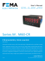
1
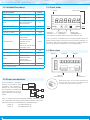
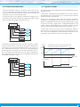
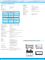
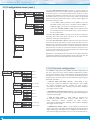
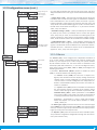
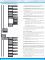
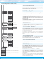
User’s Manual
ELECTRONICS
FOR
INDUSTRIAL
AUTOMATION
PANEL METERS . SIGNAL CONVERTERS . LARGE DISPLAYS
Series M . M60-CR
Chronometer, time counter
PANEL meters
Chronometer and time counter, with 14 mm digit height. Configurable with up and down counting
modes. Independent controls for start, stop and reset. Display modes in decimal format and sexagesimal (clock) format. Standard 96 x 48 mm size (1/8 DIN). Reading with 6 digit display. Fast access to
alarm setpoints, special modes for counting exceeded time and totalized counting times, ‘on power
up’ function, configurable led brightness. Universal AC and DC power. Up to 3 optional modules for
output and control (relays, analog outputs, Modbus RTU communications, RS-485 ASCII, RS-232, ...).
www.fema.es
3215r06
Tel. (+34) 93.729.6004 [email protected]
FEMA ELECTRÓNICA . Series M . M60-CR
1. Panel meter M60-CR
Chronometer and time counter, size 96 x 48 mm (1/8 DIN)
Panel meter 96 x 48 mm (1/8 DIN) and 6 digits with 14 mm digit
height, and function chronometer and time counter. Time displayed
in different formats covering hours, minutes, seconds, cents of seconds and days. Reading configurable in decimal and sexagesimal
(clock) formats. Up and down counting functions, with configurable
preset value.
Controls
Independent controls for ‘start’, ‘stop’ and ‘reset’ (see section 1.6).
Controls activated by default through free potential contacts. Configurable for activation with other control signals (NPN, PNP, inductive, ...).
Reset
Reset control is provided by connection at the rear of the instrument,
configurable to activate by edge or by level. Front reset configurable
at the ‘LE’ keypad (see section 1.7). Automatic reset configurable
when reaching an alarm setpoint (see section 1.7).
Special functions
Special functions with activation by connection at the rear of the instrument. Includes control for counting direction, total accumulated
times, total exceeded time, hold of display reading and memory of
cicles (see section 1.12.2).
Alarms
Independent alarms configurable as maximum or minimum, with
configurable activation and deactivation delays and optional inverted activation of the relay. Alarms configurable in ‘normal’ mode or
‘repeat’ mode. In ‘repeat’ mode the alarm activates every time the
configured setpoint time has passed (see section 1.12.4).
The ‘on_alarm’ parameter allows to associated a predefined function
to the activation of the alarm. Available functions are : stop counting,
activate the reset, set reading to ‘0’ or continue. Use ‘on_alarm’ configured to ‘reset’ to implement repetitive cycles of time which can be
counted by special function ‘B.2’ (see section 1.12.2).
Flash
Several options allow to configure the display flash in case of ‘stop’
or ‘start’ counting, or in case of alarm activation (see section 1.12.4).
Security on start-up
The ‘On power-up’ function defines a time of inactivity of the instrument after power-up, the status of the instrument (‘start’ or ‘stop’)
after power-up, and the option to apply a reset after power-up (see
section 1.12.2).
Memory
The instrument saves and recovers the last reading value in case of
power-loss.
Configurable ‘fast-acess’ menu
The front key ‘UP’ () gives access to a user configurable menu with
direct access to several useful functions such as alarm setpoints and/
or preset value (see section 1.12.5).
Control and retransmission options
Options for signal retransmission and control with 1, 2 and 3 relays,
analog outputs isolated, communications in Modbus RTU, RS-485
ASCII and RS-232. Special options with 4 and 6 relay outputs (see
section 2).
Mechanical
Front protection IP54 with optional IP65. Connections by plug-in
screw terminals. For industrial applications.
1.1 How to order
Model
M60
-
CR
Power
-
H
-H
-L
(85-265 Vac/dc)
(11/60 Vdc,
24 Vac, 48 Vac)
Option 1
-
-R1
-AO
-RTU
-S4
-S2
-
2
Option 2
(1 relay)
(analog output)
(Modbus RTU)
(RS-485)
(RS-232)
(empty)
Option 3
-
Others
-NBT
-65
-G
(no buttons)
(front IP65)
(green led)
FEMA ELECTRÓNICA . Series M . M60-CR
Index
1. Panel meter M60-CR . . . . . . . . . . . . . . . . . . . . . . 2
1.1 How to order . . . . . . . . . . . . . . . . . . . . . . . . . 2
1.2 Included functions . . . . . . . . . . . . . . . . . . . . . . 4
1.3 Power connections . . . . . . . . . . . . . . . . . . . . . 4
1.4 Front view . . . . . . . . . . . . . . . . . . . . . . . . . . 4
1.5 Rear view . . . . . . . . . . . . . . . . . . . . . . . . . . . 4
1.6 Control connections . . . . . . . . . . . . . . . . . . . . . 5
1.7 Types of reset . . . . . . . . . . . . . . . . . . . . . . . . 5
1.8 Technical specifications . . . . . . . . . . . . . . . . . . . 6
1.9 Mechanical dimensions (mm) . . . . . . . . . . . . . . . 6
1.10 How to operate the menus . . . . . . . . . . . . . . . . 7
1.11 Messages and errors . . . . . . . . . . . . . . . . . . . . 7
1.12 Configuration menu . . . . . . . . . . . . . . . . . . . . 8
1.12.1 Initial set-up . . . . . . . . . . . . . . . . . . . . . . 8
1.12.2 Configuration . . . . . . . . . . . . . . . . . . . . . . 8
1.12.3 Controls configuration . . . . . . . . . . . . . . . . 10
1.12.4 Alarms . . . . . . . . . . . . . . . . . . . . . . . . . 11
1.12.5 Fast access . . . . . . . . . . . . . . . . . . . . . . 12
1.12.6 Super fast access . . . . . . . . . . . . . . . . . . . 13
1.12.7 Menu ‘Key LE’ . . . . . . . . . . . . . . . . . . . . 13
1.12.8 Left zeros . . . . . . . . . . . . . . . . . . . . . . . 13
1.12.9 Function ‘Password’ . . . . . . . . . . . . . . . . . 13
1.12.10 Factory reset . . . . . . . . . . . . . . . . . . . . 13
1.12.11 Firmware version . . . . . . . . . . . . . . . . . . 13
1.12.12 Brightness . . . . . . . . . . . . . . . . . . . . . . 13
1.12.13 Access to optional modules . . . . . . . . . . . . 13
1.13 Full configuration menu . . . . . . . . . . . . . . . . . 14
1.14 Factory configuration . . . . . . . . . . . . . . . . . . 16
1.15 Application example 1 . . . . . . . . . . . . . . . . . . 17
1.16 Application example 2 . . . . . . . . . . . . . . . . . . 17
1.17 To access the instrument . . . . . . . . . . . . . . . . 18
1.18 Modular system . . . . . . . . . . . . . . . . . . . . . 18
1.19 Precautions on installation . . . . . . . . . . . . . . . 19
1.20 Warranty . . . . . . . . . . . . . . . . . . . . . . . . . 19
1.21 CE declaration of conformity . . . . . . . . . . . . . . 19
2. Output and control modules . . . . . . . . . . . . . . . . . 20
2.1 Module R1 . . . . . . . . . . . . . . . . . . . . . . . . . 20
2.2 Module AO . . . . . . . . . . . . . . . . . . . . . . . . . 20
2.3 Module RTU . . . . . . . . . . . . . . . . . . . . . . . . 21
2.4 Module S4 . . . . . . . . . . . . . . . . . . . . . . . . . 21
2.5 Module S2 . . . . . . . . . . . . . . . . . . . . . . . . . 22
2.6 Modules R2, R4, R6 . . . . . . . . . . . . . . . . . . . . 22
3. Other options . . . . . . . . . . . . . . . . . . . . . . . . . 24
3.1 Option NBT . . . . . . . . . . . . . . . . . . . . . . . . . 24
3.2 Option 65 . . . . . . . . . . . . . . . . . . . . . . . . . 24
3.3 Option G . . . . . . . . . . . . . . . . . . . . . . . . . . 24
4. Accessories . . . . . . . . . . . . . . . . . . . . . . . . . . 25
4.1 THM benchtop housing . . . . . . . . . . . . . . . . . . 25
4.2 Adapter DRA-M . . . . . . . . . . . . . . . . . . . . . . 25
4.3 Adapter KA96 . . . . . . . . . . . . . . . . . . . . . . . 25
4.4 WME housing . . . . . . . . . . . . . . . . . . . . . . . 25
4.5 Protector KIP . . . . . . . . . . . . . . . . . . . . . . . . 25
3
FEMA ELECTRÓNICA . Series M . M60-CR
1.2 Included functions
1.4 Front view
Functions included
Fast access
yes, configurable
1.12.5
Preset
yes, configurable
1.12.1
Reset
yes, configurable : front,
rear and/or linked to
alarm activation
Counting direction
up or down
Memory
yes, recovers at power-up
Functions ‘on alarm’
yes
Control led*
Alarms
Section
1.7
1.12.1
Logo
1.12.4
Button ‘LE’
Button ‘UP’
Button ‘SQ’
Front reset
‘Fast access‘
‘Configuration menu’
Units
Units
Special functions
control up / down
cycle counter
accumulated counter
exceeded counter
hold control
memory for ‘shorter cycle’
and ‘longer cycle’
1.12.2
* The ‘led control’ is operative only in counting modes that do not
display seconds, tenths of second or cents of seconds. It flashes ‘on’
and ‘off’ at a rate of 1 second when instrument is counting (‘start’). It
remains ‘off’ when the instrument is not counting (’stop’).
‘On Power Up’
yes
1.12.2
1.5 Rear view
Password
blocks configuration
1.12.9
Option 3
Alarms
activation delay
deactivation delay
inverted relay
locked deactivation
1.12.4
Display brightness
5 levels
1.12.12
(see section 1.12.7)(see section 1.12.5) (see section 1.12)
Option 1
Option 2
Table 1 - Functions included
1 2 3 4 5
Controls
(see section 1.6)
1.3 Power connections
Earth connection - Although a
terminal is provided for earth
connection, this connection is
optional. The instrument does
not need earth connection for
correct operation nor for compliance with the security regulations.
Power
(see section 1.3)
Detail of the plug-in screw terminals provided with
the instrument. The instrument is provided with all
terminals needed, both male and female.
890
~
+
~
-
Fuse - To comply with security regulation 61010-1, add to the power
line a protection fuse acting as disconnection element, easily accessible to the operator and identified as a protection device.
Power ‘H’ fuse 250 mA time lag
Power ‘L’
fuse 400 mA time lag
4
8 9 0
FEMA ELECTRÓNICA . Series M . M60-CR
1.6 Control connections
• Normal connections (‘con.a’) - controls for ‘start’, ‘stop’ and ‘reset’ are independent. Activation by default is by falling edge (by
short-circuit to the 0 Vdc terminal). Internal pull-up resistors are
activated. This is the normal working mode.
To work with other control signals or activations, configure the internal pull-up / pull-down resistors, the trigger level and the activation by rising or falling edge (see section 1.12.3).
1 2 3 4 5
Reset
Stop
Start
1.7 Types of reset
The reset function can be activated from three independent and configurable sources:
• Front reset - associated to the front button ‘LE’ (3). This reset can
be disabled by menu (see section 1.12.7). The front reset is activated
by levels (pressed / not pressed).
• Rear reset - connected to pin 5 at the rear terminal. It activates
by default on falling edge, by connection to the 0 Vdc terminal. Activation is configurable (see section 1.12.2) by edge (falling or rising)
or level (up or down). Trigger level is configurable between 0 and
3.9 Vdc. Internal configurable pull-up / pull-down resistors allow to
use other type of sensors (NPN, PNP, push-pull, inductives, TTL, ...).
• Alarm reset - alarms 1, 2 and 3 can be configured to activate a
certain function (a reset for example) when alarm activates (see section 1.12.4). This configuration creates infinite loops which can be
counted by using function ‘B.2 cycles’ (see section 1.12.2).
Vexc.
0 V
• Alternative connections (‘con.b’) - the ‘start’ and ‘stop’ controls
share the same terminal ‘1’. Terminal ‘1’ at high level activates the
‘start’. Terminal ‘1’ at low level activates the ‘stop’. The ‘reset’ control is independent at terminal 5. Terminal ‘3’ is now dedicated to
activate signal ‘B’. See section 1.12.2 for more information on functions associated to the activation of the ‘B’ signal. Activating on
the configuration menu a ‘B’ function, automatically activates the
‘alternative connections’ mode.
Reading
Chronometer with ‘reset’ activation when reading reaches setpoint 1 (‘15.00’ minutos)
Setpoint 1
15.00
0.00
15.00
1 2 3 4 5
30.00
45.00
Minutes
Cycle counter
Reset
function ‘B’
0
1
2
Minutes
Start / Stop
Vexc.
0 V
5
FEMA ELECTRÓNICA . Series M . M60-CR
1.8 Technical specifications
Digits
number of digits
led color
digit height
6
7 segments led
red or green
14 mm
Reading modes
* Meaning : (d=days, h=hours, m=minutes, s=seconds, c=cents of second)
Sexagesimal reading modes
mm.ss.cc
mmmm.ss
hh.mm.ss
hhhh.mm
dd.hh.mm
dddd.hh
Mechanical
mounting connections
housing material weight front size
panel cut-out
depth from panel panel
plug-in screw terminal
ABS, polycarbonate (V0)
<150 grams
96 x 48 mm (1/8 DIN)
92 x 44 mm
91 mm (including terminals)
Temperature
operation storage warm-up time
from 0 to +50 ºC
from -20 to +70 ºC
15 minutes
Decimal reading modes
ssssss
mmmmmm
hhhhhh
sssss.s
mmmmm.m
hhhhh.h
ssss.ss
mmmm.mm
hhhh.hh
maximum reading
minimum reading
99.59.59 / 99.23.59 / 999999
-19.59.59 / -19.23.59 / -199999
Accuracy of the quartz
Thermal drift ±0.01 %
20 ppm / ºC
Controls
default signal
configurable for ...
start, stop, reset
free potential contact
NPN, PNP, Namur, pick-up, TTL, inductive, mechanical, ...
maximum Vdc on terminals±30 Vdc
excitation voltage
configurable +18 Vdc, +15 Vdc, +9 Vdc, +5 Vdc
maximum current
70 mA
protection yes, current limited to 70 mA
Display refresj
retention memory
12 refresh/ second
yes, recovers counting value in case of
power-loss
Power
power ‘H’
power ‘L’
isolation*
consumption
85 to 265 Vac/dc
11 to 60 Vdc and 24/48 Vac
2500 Veff with power‘H’
1500 Veff with power ‘L’
*tested during 60 seconds.
<1.5 W only meter
<4.0 W meter with options
Configuration
3 buttons front keypad
Front protection
IP54 standard
IP65 optional (see section 3.2)
1.9 Mechanical dimensions (mm)
48
96
16
75
Output and control options relays, analog outputs, serial communications (see section 2)
44
Panel
cut-out
92
6
8
FEMA ELECTRÓNICA . Series M . M60-CR
1.10 How to operate the menus
Example of operation inside the
‘configuration menu’.
The instrument has two menus accessible to the user :
‘Configuration menu’ (key SQ) (<)
‘Fast access’ menu (key UP) (5)
(1)
(6)
(4)
1. The SQ (<) key enters into the
‘configuration menu’.
(4)
2. The SQ (<) key enters into the
‘Func’ option menu.
(4)
3. The UP (5) key moves through
the menu options.
(5)
Configuration menu
The ‘configuration menu’ modifies the configuration parameters to
adapt the instrument to the application needs. To access the ‘configuration menu’ press for 1 second the SQ (<) key. This access can
be blocked by activating the ‘Password’ (‘PASS’) function. While
operating the ‘configuration menu’, the alarm status is ‘hold’ to the
status they had before accessing the menu, and the output and control modules remain in ‘error’ state. When leaving the ‘configuration
menu’, the instrument applies a system reset, followed by a brief
disconnection of the alarms and the output and control modules.
Functionality is then recovered.
(2)
Function
mode
(3)
(3)
(5)
(3)
(5)
(3)
(3)
(6)
4. The SQ (<) key selects the
desired range and returns to the
‘Func’ menu.
5. The LE (3) key leaves the actual menu level and moves to the
previous menu level.
(3)
For a detailed explanation on the ‘configuration menu’ see section
1.12, and for a full view of the ‘configuration menu’ structure see
section 1.13.
6. The LE (3) key leaves the ‘configuration menu’. Changes are applied and saved at this moment.
‘Fast access’ menu
The ‘fast access’ menu is an operator configurable menu, providing
fast and direct access to the most usual functions of the instrument
with a single key pad stroke. Press key UP (5) to access this menu.
See section 1.12.5 for a list of functions eligible for ‘fast access’ in
this instrument. The ‘Password’ (‘PASS’) function does not block access to this menu. Accessing and modifying parameters in the ‘fast
access’ menu does not interfere with the normal functionality of the
instrument, and it does not generate any system reset when validating the changes.
1.11 Messages and errors
The error messages are shown on display in flash mode.
Messages and errors
‘Err.1’
incorrect password.
‘Err.2’
at ‘oPt.X’ menu entry. Installed module is not recognized.
Front key pad description
‘Err.8’
excitation voltage overload.
Key SQ (<) - press the SQ (<) key for 1 second to access the ‘configuration menu’. Inside the menu, the SQ (<) key functions as a
‘ENTER’ key. It selects and accesses the menu option currently displayed. At menus with numerical value entries, it validates the number displayed.
‘999999’ + flashing mode. Reading is in overrange.
‘-199999’ + flashing mode. Reading is in underrange.
Table 2 - Messages and error codes
Key UP (5) - the UP (5) key gives access to the ‘fast access’ menu.
Inside the menus, it moves vertically through the different menu options. At menus with numerical value entries, it modifies the digit
selected by increasing its value to 0, 1, 2, 3, 4, 5, 6, 7, 8, 9.
Key LE (3) - inside the menus, the LE (3) key functions as the ‘ESCAPE’ key. It leaves the selected menu, and eventually, will leave the
whole menu. When leaving the ‘configuration menu’ with the LE (3)
key, the changed parameters are activated. At menus with numerical value entries, the LE (3) key allows to select the active digit. To
modify the value of the selected digit use the UP (5) key.
Menu ‘rollback’
After 30 seconds without interaction from the operator, the instrument will rollback and leave the ‘configuration menu’ or the ‘fast access’ menu. All changes will be discarded.
7
FEMA ELECTRÓNICA . Series M . M60-CR
1.12 Configuration menu
Press ‘SQ’ (<) for 1 second to access the ‘configuration menu’.
For a description on how to operate inside the menus see section
1.10. For a full vision of the ‘configuration menu’ structure see
section 1.13.
0.00.00 to 99.59.99
Function
mode
View format
0.00.00 to 99.59.59
0.00.00 to 99.23.59
0.00 to 9999.59
0.00 to 9999.59
1.12.1 Initial set-up
To configure the initial set up of the instrument, select the viewing
format, configure the up or down counting mode and assign the preset value.
Enter the ‘Function mode’ (‘Func’) menu and select the ‘View’ format desired.
• ‘MM.SS.cc’ - clock format, minutes, seconds and cents.
• ‘hh.MM.SS’ - clock format, hours, minutes and seconds.
• ‘dd.hh.MM’ - clock format, days, hours and minutes.
• ‘MMMM.SS’ - counter of minutes and seconds.
0.00 to 9999.23
• ‘hhhh.MM’ - counter of hours and minutes.
0 to 999999
• ‘dddd.hh’ - counter of days and hours.
0.0 to 99999.9
• ‘SSSSSS’ - counter of seconds.
0.00 to 9999.99
• ‘SSSSS.S’ - counter of seconds with one decimal.
• ‘SSSS.SS’ - counter of seconds with two decimals.
0 to 999999
• ‘MMMMMM’ - counter of minutes.
0.0 to 99999.9
• ‘MMMMM.M’ - counter of minutes with one decimal.
0.00 to 9999.99
• ‘MMMM.MM’ - counter of minutes with two decimal.
0 to 999999
• ‘hhhhhh’ - counter of hours.
0.0 to 99999.9
• ‘hhhhh.h’ - counter of hours with one decimal.
• ‘hhhh.hh’ - counter of hours with two decimal.
0.00 to 9999.99
At the ‘Preset’ (‘PrSt’) menu select the preset value. The preset value
will load on display when reset function activates. See section 1.7 for
a description on the different activation modes for the reset.
Up
Counting
direction
Down
Preset value
-199999 to 999999
Preset
Access the ‘Counting direction’ (‘dIr’) and select ‘uP’ for up counting
or ‘doWn’ for down counting.
1.12.2 Configuration
Additional configuration parameters for the instrument.
The ‘On Power Up’ (‘on.Pu’) menu configures functions to apply at
start-up. It applies only to instrument restart after power loss. It does
not apply to instrument restart due to change in configuration.
Configuration
On power-up
Delay
Reset
State
Seconds
• parameter ‘Delay’ (‘dLAy’) assigns a waiting time in seconds. The instrument waits the configured time before starting normal function.
During this waiting time, the display shows all decimal points on in
flash mode, all alarms are in ‘oFF’ state, there is no signal acquisition
and there is no communications or control being performed. After
the configured time is over, the instrument starts in normal function.
Application - the start-up process for an automation system implies
that different parts of the system (engines, actuators, controllers, ...)
have different start-up times. The ‘Delay’ function gives time to the
instrument to wait until the slowest part of the system is fully functional before executing actions on the system (signal reading, relay
activation, ...).
• the ‘Reset’ (‘rSt’) parameter will execute a reset of the counter
each time the instrument is restarted.
8
FEMA ELECTRÓNICA . Series M . M60-CR
1.12 Configuration menu (cont.)
Flash
• the ‘State’ (‘StAt’) parameter controls the state of the counter after
power-up. Select ‘Strt’ to count after power-up or ‘StoP’ to remain
stopped after power-up.
‘Flash on stop’
‘Flash on start’
activates by edge
Rear reset
activates by level
The whole power-up process of the instrument is explained as follows : instrument waits the time defined at ‘Delay’, it then resets (or
not) the counter according to parameter ‘Reset’, then it counts or
remains stopped according to parameter ‘StAt’ and then it checks for
external controls ‘start’, ‘stop’ and ‘reset’.
The ‘Flash’ menu (‘FLSh’) controls the activation of the rear reset by
edge (‘EdGE’) or by level (‘LEVL’).
The ‘Rear reset’ menu (‘r.rSt’) controls the activation of the display
flashing when instrument is stopped (‘StP.F’) and / or when instrument is counting (‘StP.F’).
Function
on channel ‘B’
Function assigned to
channel ‘B’. Selecting a ‘B’ function
automatically
activates connection type
‘Con.2’ (see section
1.6)
The ‘Function on channel ‘B’’ menu (‘Fn.b’) controls the activation
of special functions on channel ‘B’ (rear terminal 4). If a ‘B’ function
is selected, signal connections change to ‘alternative connections’ as
indicated at section 1.6.
Following is an explanation for each of the 6 ‘B functions’ available.
• function ‘B.1 control up / down’ (‘Fn.b.1’) controls the up or down
counting based on the state of input signal at channel ‘B’.
Next menu entry gives access to the configuration parameters of the ‘channel ‘B’ function’ (‘Fn.b’) previously selected. If no function has been selected,
menu entry indicates ‘Fn.b.n’. Following is an explanation for menus ‘Fn.b.1’
to ‘Fn.b.6’.
• function ‘B.2 cycles’ (‘Fn.b.2’) enables an internal counter (from
0 to 999999) which can be made visible on display by activation of
channel ‘B’ signal. There are several events that can add ‘+1’ to this
internal counter :
• ‘on alarm 1’ (‘o.AL1’) select ‘on’ to add ‘+1’ each time alarm
1 activates.
Function B.1
control up / down
• ‘on alarm 2’ (‘o.AL2’) select ‘on’ to add ‘+1’ each time alarm
2 activates.
• ‘on alarm 3’ (‘o.AL3’) select ‘on’ to add ‘+1’ each time alarm
3 activates.
Function B.2
cycles
‘on alarm 1’
‘on alarm 2’
‘on alarm 3’
on ‘reset’
Function B.3
accumulated
Format
• ‘on reset’ (‘o.rSt’) select ‘on’ to add ‘+1’ each time reset
function activates.
• function ‘B.3 accumulated’ (‘Fn.b.3’) enables an internal counter
which can be made visible on display by activation of channel ‘B’
signal. To reset the accumulated counter, view the counter on display and activate the reset (front or rear). The accumulated counter
counts the totalized time that the instrument has been counting or
stopped (needs to be powered-up).
• parameter ‘Format’ (‘ForM’) configures the view format for
the accumulated counter. Value ‘ch.A’ views in same format
as the main instrument.
• at parameter ‘Count’ (‘cnt’) select ‘ALWS’ to count the total
time that the instrument has been powered. Select ‘Strt’ to
count the total time the instrument has been counting. Select ‘StoP’ to count the total time the instrument has been
stopped.
Count
9
FEMA ELECTRÓNICA . Series M . M60-CR
1.12 Configuration menu (cont.)
Function B.4
exceeded
• function ‘B.4 exceeded’ (‘Fn.b.4’) enables an internal counter for
exceeded time, which can be made visible on display by activation of
channel ‘B’ signal. To reset the exceeded counter, view the counter
on display and activate the reset (front or rear). The reset leaves the
exceeded counter at a value of ‘0’ and in ‘Stop’ mode. The exceeded
counter counts the totalized time after a certain event triggers the
start of the internal counter.
Format
• at the ‘Start’ (‘Strt’) parameter select ‘o.AL1’ to start the
exceeded counter when alarm 1 activates. Select ‘o.AL2’ or
‘o.AL3’ to trigger the counter on activation of alarm 2 or 3.
‘Start’
• parameter ‘Format’ (‘ForM’) configures the view format for
the exceeded counter. Value ‘ch.A’ views in same format as
the main instrument.
• function ‘B.5 hold’ (‘Fn.b.5’) controls the hold of the display by
controlling the state of the signal at channel ‘B’. The chronometer
continues counting on the background.
Function B.5
‘hold’
• function ‘B.6 max / min’ (‘Fn.b.6’) internally saves the maximum
and minimum times recorded of a certain cycle. Each time a reset is
activated, the instrument compares the actual reading value with the
previous saved memorized values. It replaces the minimum value if
the actual value is smaller. It replaces the maximum value if the actual value is larger. Minimum and maximum values are visible through
front key UP (5) (see section 1.12.5).
Function B.6
‘Max / min’
Application - a production process executes a reset signal each time
a production element has been finished. At the end of the day, the
maximum and minimum production times can be accessed.
1.12.3 Controls configuration
No pull
Controls
Pulls for
‘Start’ and ‘Stop’
Pull up
Pull down
by rising edge
Activation for
‘Start’ and ‘Stop’
by falling edge
No pull
Pulls for reset
Pull up
Pull down
by rising edge
Activation for
‘reset’
10
by falling edge
The ‘Controls’ configuration menu (‘SnSr’) provides configuration for
the ‘start’, ‘stop’ and ‘reset’ controls. Default configuration is activation by free potential contacts, with activation by falling edge (direct
connection to terminal 0 Vdc). The following parameters allow to
configure the instrument controls to work with other type of signals
(NPN, PNP, inductives, ...).
• ‘Pulls for ‘Start’ and ‘Stop’’ (‘PuL.S’) - select ‘P.uP’ to activate pull-up resistors (needed for NPN sensors). Select ‘P.dn’
to activate pull-down resistors (needed for PNP sensors).
Select ‘no’ to deactivate pulls. Selecting a pull resistors configures
the trigger level to 2,5 Vdc.
• ‘Activation for ‘Start’ and ‘Stop’’ (‘Act.S’) - select (‘on_h’) to activate the ‘Start’ and ‘Stop’ controls by rising edge. Select (‘on_0’) to
activate by falling edge.
• ‘Pulls for reset’ (‘PuL.r’) - select ‘P.uP’ to activate pullup resistors (needed for NPN sensors). Select ‘P.dn’ to activate pull-down resistors (needed for NPN sensors).
Select ‘no’ to deactivate pulls. Selecting a pull resistors configures
the trigger level to 2,5 Vdc.
• ‘Activation for ‘Reset’’ (‘Act.r’) - select (‘on_h’) to activate the
‘Reset’ control by rising edge. Select (‘on_0’) to activate by falling
edge. Additionally, reset signal can be configured to activate by levels instead of edges (see section 1.12.2). In case of activation by lev-
FEMA ELECTRÓNICA . Series M . M60-CR
1.12 Configuration menu (cont.)
Trigger level
Trigger level (from
0 to 31). Each
level is approx.
0.128 Vdc.
Excitation
voltage
Antirrebound
els, value ‘on_h’ activates the reset on high signal value, and value
‘on_0’ activates reset on low signal. Front reset activates always by
state.
• ‘Trigger level’ (‘trIG’) - select the signal voltage level at which the
instrument will consider that the signal has reached the activation
level. Selectable from 0 to 31 levels, where each level is approx.
imately 0.128 Vdc. Trigger level is the same for channels ‘start’ and
‘stop’. Reset channel has a fixed trigger to 2,5 Vdc. The three leds to
the left of the value reflect the state (‘0’ or ‘1’) of control channels
‘Start’, ‘Stop’ and ‘Reset’.
• ‘Excitation voltage’ (‘V.EXc’) - power provided by the instrument
to power-up the sensors (if needed) used to control the signals
‘start’, ‘stop’ and / or ‘reset’, or to be used as an active signal (‘1’) for
special connections. Select the for the excitation voltage at 5 Vdc,
9 Vdc, 15 Vdc or 18 Vdc. Select ‘no’ to disable the excitation voltage.
Antirrebound filter
(0 to 1000 mSec.)
• ‘Antirrebound filter’ (‘rbnd’) - Vlue between 0 mSeconds and
1000 mSeconds. when a signal is received, detection of additional
signals is inhibited for the time defined in this parameter. Recommended value for a mechanical contact sensor is 100 mSeconds.
Applies to ‘start’, ‘stop’ and ‘reset’ signals.
1.12.4 Alarms
Alarms
Deactivated
Alarm 1
Alarm mode
Normal
Repeat
Type of alarm
Setpoint
The ‘Alarms’ (‘ALr’) menu configures the independent activation of
up to 3 relay outputs, installed with the R1 optional modules (see
section 2.1). For outputs up to 4 and 6 relays, see special modules
R2, R4 and R6 at section 2.6. The alarm states are indicated in the
front display with leds marked as ‘1’, ‘2’ and ‘3’.To configure an alarm,
enter into the alarm menu (‘ALr1’, ‘ALr2’ or ‘ALr3’) and configure the
following parameters :
• parameter ‘Alarm mode’ (‘Mode’) allows to disable the alarm
(‘oFF’) or to select between two working modes :
•in ‘normal’ mode (‘norM‘) the alarm has a setpoint configured, that activates when the display reading reaches the
setpoint value. It can be configured as a ‘maximum alarm’ or
‘minimum alarm’. Provides configuration for independent activation and deactivation delays, flash control and action selection on activation.
• in ‘repeat’ mode (‘rEPt’) the alarm activates each time that
the chronometer reaches a multiple of the setpoint. Alarm
remains active during the time indicated at parameter ‘deactivation delay’ (‘dEL.1’). Other parameters on the ‘Alarm’
menu have no effect in this mode. This mode is not functional
in viewing modes with tenths of second or cents of second.
Application : chronometer in ‘mm.ss’ mode with a’repeat’
alarm and setpoint 1 at ‘15.00’. Alarm activates ar ‘15.00’,
‘30.00’, ‘45.00’, etc.
• at ‘Alarm type’ (‘TypE’) select the alarm to act as a maximum type
alarm (‘MAX’) or a minimum type alarm (‘MIn’). The maximum type
alarm (or minimum type alarm) activates when the display value is
higher (or lower) than the setpoint value.
• at ‘Setpoint’ (‘SEt’) enter the value for the alarm activation point.
This parameter is eligible for configuration through the ‘Fast access’
menu (see section 1.12.5).
11
FEMA ELECTRÓNICA . Series M . M60-CR
1.12 Configuration menu (cont.)
Activation delay
Deactivation
delay
Inverted relay
‘Locked alarm’
Continue
‘On alarm’
To zero
To preset
Stop
‘Alarm flash’
• at ‘Activation delay’ (‘dEL.0’) configure the delay to apply before
alarm activation. The activation delay starts counting when the setpoint value is passed. Value from 0.0 to 99.9 seconds.
• at ‘Deactivation delay’ (‘dEL.1’) configure the delay to apply
before alarm deactivation. The deactivation delay starts counting
when the setpoint value plus the hysteresis value, is passed. Value
from 0.0 to 99.9 seconds.
• the ‘Relay inverted’ (‘r.Inv’) parameter inverts the normal relay
connections. When set to ‘on’ the relay will be active when alarm is
inactive. For security applications where an inactive relay controls
the shutdown of the system.
• the ‘Locked alarm’ (‘A.Lck’) parameter disables the automatic
deactivation of the alarm. Alarm deactivation must be performed
manually, by pressing the ‘LE’ front button (see section 1.12.7)
• the ‘On alarm’ (‘on.AL’) parameter assigns a predefined behavior
when alarm activates.
• select ‘cont’ to continue counting.
• select ‘to_0’ to load ‘0’ on displays Parameter ‘deactivation
delay’ (‘dEL.1’) automatically configures to 1 second.
• select ‘to_p’ to load preset value on display. Parameter ‘deactivation delay’ (‘dEL.1’) automatically configures to 1 second.
• select ‘stop’ to stop the counting.
• set the ‘Alarm flash’ (‘AL.FL’) parameter to ‘on’ to activate the
flash of the display when alarm is active. To manually deactivate the
flash mode, press any of the front keys or change the state of any of
the control signals ‘start’, ‘stop’ or ‘reset’.
1.12.5 Fast access
The ‘UP’ (5) key at the front of the instrument gives access to a list
of functions configurable by the operator. See section 1.10 for an explanation on how to operate the ‘fast access’ menu.
Tools
Key UP
(‘Fast access’)
Setpoint 1
• the ‘Setpoint 1’ (‘ALr1’) function allows to visualize and modify the
alarm 1 setpoint through the ‘fast access’ menu.
Setpoint 2
• the ‘Setpoint 2’ (‘ALr2’) function allows to visualize and modify the
alarm 2 setpoint through the ‘fast access’ menu.
Setpoint 3
• the ‘Setpoint 3’ (‘ALr3’) function allows to visualize and modify the
alarm 3 setpoint through the ‘fast access’ menu.
Memory of
maximum
Memory of
minimum
Memory of
cycles
Preset value
12
The ‘Key UP (Fast access)’ (‘K.uP’) menu allows to select which functions will be accessible through the ‘fast access’ menu. Select ‘on’ to
activate each function.
• the ‘Memory of maximum’ (‘MAX’) or ‘Memory of minimum’
(‘MIn’) functions allow to visualize the maximum or minimum reading value stored in memory. To reset this value, visualize the memory
value at the ‘fast access’ menu with key UP (5) and when message
‘rSt’ is displayed, press (<) to reset.
• the ‘Memory of cycles’ (‘cYcL’) function allow to visualize and reset
the memory of cycles. To reset this value, visualize the memory value
at the ‘fast access’ menu with key UP (5) and when message ‘rSt’
is displayed, press (<) to reset. The memory of cycles countes ‘+1’
each time a reset alarm occurs (‘on_AL’ / ‘to_0’ or ‘to_P’) or a reset
by ‘overrange’ / ‘underrange’ occurs.
• the ‘Preset value’ (‘PrSt’) function allows to visualize and modify
the preset value configured.
FEMA ELECTRÓNICA . Series M . M60-CR
1.12 Configuration menu (cont.)
1.12.6 Super fast access
If only a single function is selected for the ‘fast access’ menu, pressing the the ‘UP’ (5) key will shortly display the function name and
then automatically jump to the function value.
1.12.7 Menu ‘Key LE’
The ‘LE’ (3) key at the front of the instrument can be configured to
activate several functions. Only one function can be assigned to the
‘LE’ (3) key
No function
Key LE
• the ‘No function’ (‘nonE’) value assigns no function.
Reset
• the ‘Reset’ (‘rSt’) value asigns the reset funtion to the ‘LE’ (3) key.
• the ‘Reset + Start’ (‘r.Str’) value asigns the reset and start function
to the ‘LE’ (3) key.
• the ‘Alarm unlock’ (‘A.Lck’) value assigns the manual unlock of the
alarms function, for instruments with the ‘Locked alarms’ (‘A.Lck’)
function activated (see section 1.12.4)
Reset + Start
Alarm unlock
With left zeros
Left zeros
Without left zeros
1.12.8 Left zeros
The ‘Left zeros’ (‘L.ZEr’) parameter controls the left zeros on or off.
1.12.9 Function ‘Password’
At the ‘Password’ (‘PASS’) menu select a 6 digit code to block access
to the ‘configuration menu’. Instrument configuration will not be accessible to non authorized personnel. To activate the ‘Password’ select ‘on’ and introduce the code.
Password
The code will be requested when trying to access the ‘configuration
menu’ (key ‘SQ’ (<)). The ‘fast access’ menu is not password protected.
Factory reset
1.12.10 Factory reset
At the ‘Factory reset’ (‘FAct’) menu, select ‘yes’ to load the default
factory configuration for the instrument (see section 1.14).
Version
Minimum
Brightness
The ‘Version’ (‘VEr’) menu informs of the current firmware version
installed in the module.
Standard
Maximum
Configuration menu for the module installed at Opt.1
1.12.12 Brightness
At the ‘Brightness’ (‘LIGh’) menu select the light intensity for the
front leds. With this function it is possible to adapt the instrument to
the environment light intensity.
1.12.13 Access to optional modules
Option 1
Configuration menu for the module installed at Opt.2
Option 2
Configuration menu for the module installed at Opt.3
Option 3
1.12.11 Firmware version
Menus ‘OPt.1’, ‘OPt.2’ and ‘OPt.3’ give access to the ‘configuration
menus’ of the output and control modules installed at slots Opt.1,
Opt.2 and Opt.3.
See section 2 for a list of output and control modules available for
each slot. The ‘configuration menu’ of each module is described at
the User’s Manual of each module.
13
FEMA ELECTRÓNICA . Series M . M60-CR
1.13 Full configuration menu
Press ‘SQ’ (<) for 1 second to access the ‘Configuration menu’. See
section 1.12 for a description of each menu entry.
0.00.00 to 99.59.99
Function
mode
View format
Function
on channel ‘B’
0.00.00 to 99.59.59
Function assigned to
channel ‘B’. Selecting a ‘B’ function
automatically
activates connection type
‘Con.2’ (see section
1.6)
0.00.00 to 99.23.59
0.00 to 9999.59
0.00 to 9999.59
0.00 to 9999.23
0 to 999999
0.0 to 99999.9
Next menu entry gives access to the configuration parameters of the ‘channel ‘B’
function’ (‘Fn.b’) previously selected. If no function has been selected, menu entry
indicates ‘Fn.b.n’. Following is an explanation for menus ‘Fn.b.1’ to ‘Fn.b.6’.
0.00 to 9999.99
0 to 999999
0.0 to 99999.9
Function B.1
control up / down
0.00 to 9999.99
0 to 999999
0.0 to 99999.9
0.00 to 9999.99
Function B.2
cycles
‘on alarm 1’
‘on alarm 2’
Up
Counting
direction
Preset value
-199999 to 999999
Preset
Configuration
On power-up
‘on alarm 3’
Down
Delay
Seconds
on ‘reset’
Function B.3
accumulated
Format
Reset
State
Flash
Count
‘Flash on stop’
Function B.4
exceeded
‘Flash on start’
activates by edge
Rear reset
14
activates by level
Format
FEMA ELECTRÓNICA . Series M . M60-CR
1.13 Full configuration menu (cont.)
‘Start’
Alarms
Disabled
Alarm 1
Alarm mode
Function B.5
‘hold’
Normal
Repeat
Type of alarm
Function B.6
‘Max / min’
Setpoint
No pull
Controls
Pulls for
‘Start’ and ‘Stop’
Activation for
‘Start’ and ‘Stop’
Pull up
Pull down
Deactivation
delay
by rising edge
Inverted relay
by falling edge
No pull
Pulls for reset
Activation delay
Pull up
‘Locked alarm’
Continue
‘On alarm’
Pull down
To zero
To preset
by rising edge
Activation for
‘reset’
Trigger level
Stop
by falling edge
Trigger level (from
0 to 31). Each
level is approx.
0.128 Vdc.
‘Alarm flash’
Excitation
voltage
Antirrebound
Antirrebound filter
(0 to 1000 mSec.)
15
FEMA ELECTRÓNICA . Series M . M60-CR
1.13 Full configuration menu (cont.)
Configuration menu for the module installed at Opt.1
Tools
Key UP
(‘Fast access’)
Option 1
Setpoint 1
Configuration menu for the module installed at Opt.2
Option 2
Setpoint 2
Configuration menu for the module installed at Opt.3
Option 3
Setpoint 3
Memory of
maximum
1.14 Factory configuration
Function mode
View format
Counting direction
Preset
Memory of
minimum
Memory of
cycles
Configuration
‘On power-up’
Delay
Reset
State
Flash
‘Flash on stop’
‘Flash on start’
Rear reset
Function on channel ‘B’
Preset value
Key LE
No function
Reset + Start
Alarm unlock
With left zeros
Without left zeros
Password
Factory reset
Version
Minimum
Brightness
Standard
Maximum
16
0 seconds
off
stopped (‘StoP’)
off
off
activates by edges (‘EdGE’)
no
Controls
Pulls for ‘start’ and ‘stop’ pull-up (‘P.uP’)
Activation for ‘start’ and ‘stop’ by falling edge (‘on_0’)
Pulls for reset
pull-up (‘P.uP’)
Activation for reset
by falling edge (‘on_0’)
Trigger level
2.56 Vdc (level 20)
Excitation voltage
15 Vdc
Antirrebound filter
disabled (0 mSeconds)
Reset
Left zeros
hh.MM.SS
up
00.00.00
Alarms 1,2 and 3
Mode
Type of alarm
Setpoint
Activation delay
Deactivation delay
Inverted relay
‘Locked alarms’
‘On alarm’
‘Alarm flash’
off (disabled)
of maximum
0
0.0 seconds
0.0 seconds
off
off
continue
off
Herramientas (‘TooL’)
‘Fast acess’ (key UP)
Setpoint 1
Setpoint 2
Setpoint 3
Memory of maximum
Memory of minimum
Cycles
Preset
Ley ‘LE’
Left zeros
Password
Brightness
off
off
off
off
off
off
off
off
reset function
off
off
3
FEMA ELECTRÓNICA . Series M . M60-CR
1.15 Application example 1
1.16 Application example 2
In an industrial process of electrolytic bath, the wetted parts need
to be removed from the bath and replaced with new parts every 20
minutes. The process of removing and adding parts to the electrolytic bath is automated and takes 15 seconds. During these 15 seconds, the system of electrolytic bath should receive no power supply,
which must be reactivated after 15 seconds, when new items are
immersed in the bath.
The M60-CR chronometer can be configured to activate a relay output every 20 minutes, and this relay must remain active for 15 seconds. After this time, the relay will deactivate.
Additionally, the system needs the counter to start counting as soon
as power is received, although a 60 seconds delay is needed to give
time to the first activation of the electrolytic bath. Counter must continue counting from the value it had before the power was removed.
Configuration would be as indicated below :
• View format
‘Func’ / ‘View’ ‘hh.mm.ss’
• Counting direction
‘Func’ / ‘dIr’
up (‘uP’)
• Preset value
‘Func’ / ‘PrSt’ ‘0.00’
• Delay on power-up
‘conF’ / ‘on_Pu’ / ‘dLAY’ 60 seconds
• Initial reset disabled
‘conF’ / ‘on_Pu’ / ‘rSt’ ‘oFF’
• Start counting after power-up
‘conF’ / ‘on_Pu’ / ‘StAt’ start (‘Strt’)
• Alarm mode
‘ALr’ / ‘ALr1’ / ‘Mode’ repeat (‘rEPt’)
• Alarm every 20 minutes
‘ALr’ / ‘ALr1’ / ‘SEt’ 20.00
• Deactivation delay
‘ALr’ / ‘ALr1’ / ‘dEL.1’ 15.0 seconds
• On alarm activation
‘ALr’ / ‘ALr1’ / ‘on_AL’ continue (‘cont’)
Alarm 1
Reading
‘06.30.00’
Chronometer with repeated activation of
alarm 1 after 20 minutes
on
05.25.00. 05.30.00 time
State of alarm 1
off
00.00
Example with preset selected at 6 hours
and 30 minutes
‘00.05.00’
‘00.00.00’
0.00.00
initial
start-up
60 seconds
An industrial process has an oven to dry different elements. The drying time of each element is variable, and the operator requires that
the setting of each drying time to be easily accessible and modifiable.
The modification of other configuration parameters must be locked.
During the process, the operator needs two signals. First signal activates a buzzer which should start 5 minutes before the end of the
scheduled drying time, and remain active for 15 seconds. The second
signal must activate at the end of the drying time and must remain
active until the operator manually the ‘reset’ signal.
The M60-CR chronometer can be configured for down counting, with
start time at preset value, which will be directly accessible and modifiable when pressing the front key UP (‘5’). All configuration parameters (except the ‘preset’ value) will be password locked. Alarm 1
will activate for 15 seconds when 5 minutes are missing to end the
process. Alarm 2 will activate when the scheduled time is over and
will remain active until the operator manually resets.
• View format
‘Func’ / ‘View’ ‘hh.mm.ss’
• Counting direction
‘Func’ / ‘dIr’
down (‘doWn’)
• Alarm 1 : alarm mode
‘ALr’ / ‘ALr1’ / ‘Mode’ normal (‘norM’)
• Alarm 1 : type of alarm
‘ALr’ / ‘ALr1’ / ‘tYPE’ minimum (‘MIn’)
• Alarm 1 : activation setpoint
‘ALr’ / ‘ALr1’ / ‘SEt’ ‘00.05.00’
• Alarm 1 : deactivation delay
‘ALr’ / ‘ALr1’ / ‘dEL.1’ 15.0 seconds
• Alarm 1 : continue counting when alarm activates
‘ALr’ / ‘ALr1’ / ‘on_AL’ continue (‘cont’)
• Alarm 2 : alarm mode
‘ALr’ / ‘ALr1’ / ‘Mode’ normal (‘norM’)
• Alarm 2 : type of alarm
‘ALr’ / ‘ALr1’ / ‘tYPE’ minimum (‘MIn’)
• Alarm 2 : activation setpoint
‘ALr’ / ‘ALr1’ / ‘SEt’ ‘00.00.00’
• Alarm 1 : when alarm activates, stop counting
‘ALr’ / ‘ALr1’ / ‘on_AL’ stop (‘stop’)
• Assign the preset value to the ‘UP’ front key
‘TooL’ / ‘K.uP’ / ‘PrSt’ ‘on’
• Configuration block by password
‘TooL’ / ‘PASS’ / ‘on’ assign the password code
on
15 seconds
20.00
40.00
60.00
Minutes
15 seconds
off
on
State of alarm 2
off
17
FEMA ELECTRÓNICA . Series M . M60-CR
1.17 To access the instrument
You may need to access the inside of the instrument to add or replace internal modules. Use a flat screwdriver to unlock the upper
clips marked with ‘A’. Then unlock the lower clips marked with ‘B’ and
remove the front cover. Let the inside of the instrument slide out of
the housing.
To reinsert the instrument make sure that all modules are correctly
connected to the pins on the display module. Place all the set into
the housing, assuring that the modules correctly fit into the internal
guiding slides of the housing. Once introduced, place again the front
cover by clipping first the upper clips ‘A’ and then the lower clips ‘B’.
Important - If your instrument was delivered with the IP65 front
seal option, accessing the inside of the instrument will permanently
break the IP65 seal on the areas of clips ‘A’ and ‘B’.
A
B
Risk of electric shock. Removing the front cover will
grant access to the internal circuits. Disconnect the
input signal to prevent electric shock to the operator.
Operation must be performed by qualified personnel
only.
1.18 Modular system
Series M panel meters are designed to create a modular system. This
modular system allows for addition, replacement or substitution of
any of the internal modules conforming the instrument. Below is a
graphic explanation for the position of each module.
Front Filter
Display Module
Optional Control Modules
Opt.2
Opt.1
Power Supply Module
Opt.3
Input Signal Module
Housing
18
FEMA ELECTRÓNICA . Series M . M60-CR
1.19 Precautions on installation
Risk of electrical shock. Instrument terminals can be connected
to dangerous voltage.
Instrument protected with double isolation. No earth connection
required.
Instrument conforms to CE rules and regulations.
1.21 CE declaration of conformity
Manufacturer
FEMA ELECTRÓNICA, S.A.
Altimira 14 - Pol. Ind. Santiga
E08210 - Barberà del Vallès
BARCELONA - SPAIN
www.fema.es - [email protected]
Products M60-CR
The manufacturer declares that the instruments indicated comply with the
directives and rules indicated below.
This instrument has been designed and verified conforming to the 61010-1
CE Security Regulation, for industrial applications.
Electromagnetic compatibility directive 2004/108/CE
Low voltage directive 2006/95/CE
Installation of this instrument must be performed by qualified personnel
only. This manual contains the appropriate information for the installation.
Using the instrument in ways not specified by the manufacturer may lead to
a reduction of the specified protection level. Disconnect the instrument from
power before starting any maintenance and / or installation action.
Security rules EN-61010-1
Instrument Fixed
Permanently connected
Pollution degree 1 and 2 (without condensation)
Isolation Double
The instrument does not have a general switch and will start operation as
soon as power is connected. The instrument does not have protection fuse,
the fuse must be added during installation.
Electromagnetic compatibility rules EN-61326-1
The instrument is designed to be panel mounted. An appropriate ventilation
of the instrument must be assured. Do not expose the instrument to excess
of humidity. Maintain clean by using a humid rag and do NOT use abrasive
products such as alcohols, solvents, etc.
EN-61000-4-2
General recommendations for electrical installations apply, and for proper
functionality we recommend : if possible, install the instrument far from
electrical noise or magnetic field generators such as power relays, electrical
motors, speed variators, ... If possible, do not install along the same conduits
power cables (power, motor controllers, electrovalves, ...) together with signal and/or control cables.
Before proceeding to the power connection, verify that the voltage level
available matches the power levels indicated in the label on the instrument.
In case of fire, disconnect the instrument from the power line, fire alarm
according to local rules, disconnect the air conditioning, attack fire with carbonic snow, never with water.
1.20 Warranty
This instrument is warranted against all manufacturing defects for a
period of 24 MONTHS from the shipment date. This warranty does
not apply in case of misuse, accident or manipulation by non-authorized personnel. In case of malfunction get in contact with your local
provider to arrange for repair. Within the warranty period and after
examination by the manufacturer, the unit will be repaired or substituted when found to be defective. The scope of this warranty is limited to the repair cost of the instrument, not being the manufacturer
eligible for responsibility on additional damages or costs.
EM environment Industrial
Immunity levels
By contact ±4 KV
By air ±8 KV
Criteria B
Criteria B
EN-61000-4-3 Criteria A
EN-61000-4-4 On AC power lines : ±2 KV
On DC power lines : ±2 KV
On signal lines : ±1 KV
Criteria B
Criteria B
Criteria B
EN-61000-4-5
Criteria B
Criteria B
Criteria B
Criteria B
Criteria B
Between AC power lines ±1 KV
Between AC power lines and earth ±2 KV
Between DC power lines ±1 KV
Between DC power lines and earth ±2 KV
Between signal lines and earth ±1 KV
EN-61000-4-6
Criteria A
EN-61000-4-8
30 A/m at 50/60 Hz
Criteria A
EN-61000-4-11
0 % 1 cycle
40 % 10 cycles
70 % 25 cycles
0 % 250 cycles
Criteria A
Criteria A
Criteria B
Criteria B
Instrument Class A, Group 1 Criteria A
Emission levels
CISPR 11 Barberà del Vallès September 2014
Daniel Juncà - Quality Manager
According to directive 2012/19/EU, electronic equipment must be recycled in a selective and controlled
way at the end of its useful life.
19
FEMA ELECTRÓNICA . Series M . M60-CR
2. Output and control modules
2.1 Module R1
2.2 Module AO
The R1 module provides 1 relay output to Series M panel meters.
Up to a maximum of 3 R1 modules can be installed in a single instrument (3 relays).
The AO module provides 1 analog output with 4/20 mA or 0/10 Vdc
configurable output range. Output current loop configurable as active (the instrument provides the excitation for the loop) or passive
(the loop is externally powered). Signal output proportional to the
instruments reading. Fully configurable scaling, in direct (positive
slope) or inverse (negative slope) scaling.
Note : for more than three relays per instrument or larger relay density per module, see special modules R2, R4 and R6 at section 2.6.
Relays with 3 contacts each (common, normally closed, normally
open), with switching capability up to 250V @ 8A.
Modules R1 are configured from the ‘ALr1’, ‘ALr2’ and ‘ALr3’ alarm
menus of the panel meter. The ‘ALrX’ menus provide configuration
for main setpoint, hysteresis, independent activation and deactivation delays, and a second setpoint to create windowed alarms.
Modules R1 are installed on slot ‘Opt.1’, ‘Opt.2’ or ‘Opt.3’ (see section 1.18) and are configured from instruments front keypad.
The R1 module can be ordered pre-installed into a Series M panel
meter, or standalone for delayed installation, as they do not require
soldering or special configuration.
Up to a maximum of 3 analog output modules can be installed in a
single instrument, all outputs isolated between them and isolated
from the power and input signal circuits.
Configuration from instrument front keypad, through menu entries
‘Opt.1’, ‘Opt.2’ or ‘Opt.3’, depending on the position the module is
installed (see section 1.18).
The RTU module can be ordered pre-installed into a Series M panel
meter, or standalone for delayed installation, as it does not require
soldering or special configuration.
3 contact relay (NC, NO, common)
Output ranges
4/20 mA active, 4/20 mA passive 0/10 Vdc
Current maximum
8A per relay (resistive load)
Accuracy (at 25 ºC)
<0.1% FS
Voltage maximum*
250 Vac continuous
Isolation
1000 Vdc
Isolation
3500 Veff
Type of terminal
plug-in screw terminal, pitch 5.08 mm
Slots allowed
‘Opt.1’, ‘Opt.2’, ‘Opt.3’ (see section 1.18)
Slots allowed
‘Opt.1’, ‘Opt.2’, ‘Opt.3’ (see section 1.18)
Opt.1
Opt.2
A B C
A B C
MV A B C
MV A B C
Signal
Terminal A
Terminal B
Terminal C
Power
Common
NO - Normally Open
NC - Normally Closed
For more information see document 3510_MODULE-M_R1_
manual_i.pdf
20
MV A B C
Opt.2
Opt.3
Opt.1
A B C
Opt.3
Type of relay
Signal
Terminal A
Terminal B
Terminal C
Jumper M
Jumper V
Power
Vexc
Signal in mA or Vdc
GND
closed for mA
closed for Vdc
For more information see document 2654_MODULE-M_AO_
manual_i.pdf
FEMA ELECTRÓNICA . Series M . M60-CR
2.3 Module RTU
2.4 Module S4
The RTU module provides a Modbus RTU communications module
for Series M of panel meters. The RTU module implements function
‘4’ (‘Read Input Registers’) of the Modbus RTU protocol, to access the
instrument registers (reading value, alarm status, memory of maximum and minimum, ...)
The S4 module provides a RS-485 communications module for Series
M of panel meters. ASCII protocol with ‘Master’ / ‘Slave’ architecture. Addressable with up to 31 modules. Frames codified in representable ASCII characters (codes 32 to 255), directly visible using
‘hyperterminal’ or similar programs.
Configuration from instrument front keypad, through menu entries
‘Opt.1’, ‘Opt.2’ or ‘Opt.3’, depending on the position the module is
installed (see section 1.18).
• Configurable for direct retransmission to remote meters M60485 (14 mm digit height) and BDF Series (60 mm and 100 mm digit
height).
The RTU module can be ordered pre-installed into a Series M panel
meter, or standalone for delayed installation, as it does not require
soldering or special configuration.
• Access to display values, alarm status, memory of maximum and
minimum, alarm setpoints, ...
Configuration from instrument front keypad, through menu entries
‘Opt.1’, ‘Opt.2’ or ‘Opt.3’, depending on the position the module is
installed (see section 1.18).
The S4 module can be ordered pre-installed into a Series M panel
meter, or standalone for delayed installation, as it does not require
soldering or special configuration.
Protocol
Modbus RTU
ProtocolASCII
Functions implemented 4 (Read_Input_Registers)
Bus type
RS-485, up to 57.6 Kbps
Bus type
RS-485, up to 57.6 Kbps
Isolation
1000 Vdc
Isolation
1000 Vdc
Slots allowed
‘Opt.1’, ‘Opt.2’, ‘Opt.3’ (see section 1.18)
Slots allowed
‘Opt.1’, ‘Opt.2’, ‘Opt.3’ (see section 1.18)
Opt.1
B A G
B A G
Opt.3
B A G
Opt.3
B A G
Opt.2
Signal
Terminal B
Terminal A
Terminal G
Power
B signal from RS-485 bus
A signal from RS-485 bus
GND
For more information see document 3498_MODULE-M_RTU_
manual_i.pdf
Opt.2
B A G
B A G
Opt.1
Signal
Terminal B
Terminal A
Terminal G
Power
B signal from RS-485 bus
A signal from RS-485 bus
GND
For more information see document 3499_MODULE-M_S4_
manual_i.pdf
21
FEMA ELECTRÓNICA . Series M . M60-CR
2.5 Module S2
2.6 Modules R2, R4, R6
The S2 module provides a RS-232 communications module for Series
M of panel meters. ASCII protocol with ‘Master’ / ‘Slave’ architecture. Addressable with up to 31 modules. Frames codified in representable ASCII characters (codes 32 to 255), directly visible using
‘hyperterminal’ or similar programs.
The R2, R4 and R6 modules provide 2, 4 and 6 relay outputs for Series
M panel meters. Relays with 3 contacts each, with switching capability up to 250 V @ 6 A.
• Access to display values, alarm status, memory of maximum and
minimum, alarm setpoints, ...
Configuration from instrument front keypad, through menu entries
‘Opt.1’, ‘Opt.2’ or ‘Opt.3’, depending on the position the module is
installed (see section 1.18).
The S2 module can be ordered pre-installed into a Series M panel
meter, or standalone for delayed installation, as it does not require
soldering or special configuration.
Modules R2, R4 and R6 are installed on slot ‘Opt.1’ (see section 1.18)
and are configured from instruments front keypad, and provide setpoint configuration, hysteresis, independent activation and deactivation delays, and second alarm setpoint for windowed alarms.
Only one module R2, R4 or R6 can be installed per instrument. Modules R2, R4 and R6 are not compatible with standard R1 modules.
The R2, R4 and R6 modules can be ordered pre-installed into a Series
M panel meter, or standalone for delayed installation, as they do not
require soldering or special configuration.
ProtocolASCII
Type of relay
3 contact relay (NC, NO, common)
Bus type
RS-232, up to 57.6 Kbps
Current maximum
6 A per relay (resistive load)
Isolation
1000 Vdc
Voltage maximum*
250 Vac continuous
Slots allowed
‘Opt.1’, ‘Opt.2’, ‘Opt.3’ (see section 1.18)
Isolation
2500 Veff
Type of terminal
plug-in screw terminal, pitch 3.81 mm
* terminals approved for 300 V (according to UL1059, groups B and
D) and 160 V (according to VDE on CAT-III and pollution degree 3).
occupies Opt.1
occupies Opt.1 and Opt.2
occupies Opt.1, Opt.2 and Opt.3
Opt.1
Opt.2
Opt.1
A B C D E
A B C D E
ABCDEF
Signal
Opt.2
GHIJKL
MNOPQR
Opt.3
A B C D E
Opt.3
Module R2
Module R4
Module R6
Power
Signal
Terminal A
Terminal B
Terminal C
GND
Rx1
Tx1
Relay
Common
Terminal D
Terminal E
Rx2
Tx2
relay 1
Power
A
Normally Open
(NO)
B
Normally Closed
(NC)
C
relay 2
D
E
F
relay 3
G
H
I
relay 4
J
K
L
relay 5
M
N
O
relay 6
P
Q
R
Table 3 - Connections for modules R2, R4 and R6
For more information see document 3500_MODULE-M_S2_
manual_i.pdf
22
For more information see document 3508_MODULES-M_R2-R4-R6_
manual_i.pdf
Th
is
p
ag
e
b
la
n
k
FEMA ELECTRÓNICA . Series M . M60-CR
23
FEMA ELECTRÓNICA . Series M . M60-CR
3. Other options
3.1 Option NBT
3.3 Option G
Instruments without front keypad. To configure the instrument,
remove the meter from the panel
and remove the front filter. Internal press buttons for configuration
are accessible. Optionally, request
the instrument preconfigured
from factory.
Green led digits option.
3.2 Option 65
Front IP65 protection, with sealing
of front filter clips.
* opening the front filter removes
the IP65 sealing permanently.
24
Without front keypad
Green digits
FEMA ELECTRÓNICA . Series M . M60-CR
4. Accessories
4.1 THM benchtop housing
Benchtop housing for Series M
and Series K of panel meters.
Handle with three selectable positions. Power connector with manual switch and fuse holder.
4.4 WME housing
Wall mount housing. Together
with the KIP protector, offer a
full IP65 protection. For Series
M and Series K of panel meters.
4.2 Adapter DRA-M
4.5 Protector KIP
Adapter for DIN rail mount, for
Series M and Series K of panel
meters.
Front IP65 protector for Series
M and Series K of panel meters.
4.3 Adapter KA96
Adapter 96 x 96 mm for 96 x 48 mm
instruments.
25
FEMA ELECTRÓNICA . Series M . M60-CR
Notes
26
FEMA ELECTRÓNICA . Series M . M60-CR
Notes
27
Panel meters
Standard 96 x 48 mm
Panel meters
Miniature 48 x 24 mm
Signal converters
Panel meters
Compact 72 x 36 mm
Large format meters
Bar meters
Isolators
Low cost
‘Customized’
instruments
mA
Vac
TrueRMS
FEMA ELECTRÓNICA, S.A.
Altimira 14 - Pol. Ind. Santiga
E08210 Barberà del Vallès
BARCELONA - SPAIN
Vdc
Pt100
Tel. +34 93.729.6004
Fax +34 93.729.6003
[email protected]
www.fema.es
TC
Aac
Hz
TrueRMS
Vac
Aac
X/5
Vdc
Adc
X/1
Pt100
Pot
Shunts
MODBUS
Load
RS-485
RS-232
BCD
Custom
?