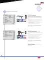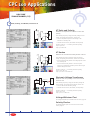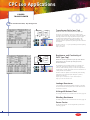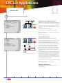
1
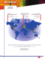
World Leader in Innovative Power System Testing Solutions
P r i m a r y
T estinG
C P - L I N E
C a t a l o g
Company Profile
C ustomer and
C o mpa ny Profi le
About our customers
Typical customers of our CP product line, which represents our products for primary testing,
are engineers and technicians working mainly in commissioning, maintenance testing, and test
fields of
• Power transformers,
• Current transformers,
• Voltage transformers,
• Power cables,
• Circuit breakers,
• Rotating machines,
and other electrical power system equipment in utilities and industry.
Our test equipment is also used for automated measuring of resistances (contact resistances,
winding resistances, grounding resistances, cable impedances), power factor, dissipation factor,
and capacitance, but also for single-phase testing of primary and secondary protective relays
(I>, V>, V< or frequency relays.)
About OMICRON
OMICRON is an international company providing innovative solutions for primary and
secondary testing.
Combining innovation, leading edge technology, and creative software solutions, OMICRON’s
sales have earned world leader status for OMICRON within this niche market. With sales in more
than 100 countries, offices in Europe, the United States, and Asia, and a worldwide network of
distributors and representatives, OMICRON has truly established its reputation as a supplier of
the highest quality.
The automated testing and documentation capabilities of OMICRON testing solutions are
important benefits in light of the changing market conditions resulting in restructured
organizations required to “do more with less”.
Today, OMICRON’s products revolve around a testing concept which provides the solutions to
many challenges created by these competitive trends in the marketplace. This integration of
lightweight and reliable hardware with flexible and user-friendly software is referred to as the
OMICRON Test Universe.
Services in the area of consulting, commissioning, relay testing and training make OMICRON´s
product range complete.
Specialization in power system testing along with visionary leadership allows OMICRON to
continue with innovative developments for its testing solutions to meet the customer needs of
the 21st century.
Subjects covered in other catalogs
Secondary Testing - CM line catalog
OMICRON’s product range in the area of secondary testing.
For a detailed list of currently available literature, please refer to
www.omicron.at/support/literature or www.omicronusa.com/support/literature.
2
Table of Contents
TA BLE OF CONTENTS
Multifunctional Primary Test System CPC 100
4
Overview
5
Interface Elements
7
Technical Data
8Applications
9
Current Transformer (CT)
12
Voltage Transformer (VT)
13
Power Transformer
14
Resistance
15
Automatic Test Procedures
16
Power Factor, Impedance Measuring
17
Reports, Offline Test Preparation
TD1 - Tangent Delta / Power Factor Testing
18
CP TD1, Technical Data (CPC 100 with CP TD1)
CU1 - Line & Ground Impedance Testing
19 CP CU1, Technical Data (CP CU1 and CP GB1)
Other Accessories
20
CP TC12 Oil Test Cell, CP CR500 Compensating Reactor
21
CP CB2 Current Booster
22
Polarity Checker, Transport Cases
23
Cables, Clamps and Plugs
Package Options
24
CPC 100 Package Overview
Current Transformer Testing / Analysis
26
CT Analyzer, Technical Data
Sweep Frequency Response Analyzer
27
FRAnalyzer, Technical Data
Dielectric Response Analyzer
28
DIRANA, Technical Data
Partial Discharge Analysis System
29
MPD 600, Technical Data
Universal Current Measuring System
30
MI 600, Technical Data
31
Contact Addresses
CPC 100 Accessories
ISO 9001 certified
3
CPC 100
Ov ervi ew
Multifunctional Primary Test System for Substation Commissioning and Maintenance
This world-wide unique system allows for automated testing of power transformers, CTs, VTs, resistance testing, and more.
Providing up to 800 A (or 2000 A with current booster) and 2000 V with a frequency range of 15-400 Hz, it also comes complete with an integrated PC.
Its software routines test a wide range of substation equipment, and automatically create customizable reports. The compact design (29 kg / 64 lbs) and
the innovative software save testing time and minimize transportation costs.
Analog voltages and currents can be measured with very high precision. Its W meters offer ranges from µW to kW to allow for a wide variety of applications.
Testing of unconventional equipment, such as Rogowski Coils or current sensors completes the spectrum. Additional applications can be added with the use
of flexible accessories to include tangent delta / power factor testing and primary measurements of power system equipment.
LIGHTWEIGHT
29 kg / 64 lbs
•Less than one fourth the weight
of equivalent conventional equipment
•Lower transportation costs saves money
•Easier handling reduces manpower needs
•Low weight reduces injury potential
ONE TEST UNIT FOR MULTIPLE USES
•Replaces need for multiple test sets
(e.g. high current and voltage sources, mW meter)
•Saves time by eliminating need for multiple training
•User-friendly interface reduces training time to one day
AUTOMATED TESTING AND REPORTING
•Prepare test plans ahead of time in office (saves time in field testing phase)
•Set up test once, push button to start (saves testing time)
•Results automatically saved (saves time and reduces errors by
eliminating manual recording of data)
•Automatic report generation (saves time by eliminating manual
report writing; accelerates project completion)
•Print reports via external PC
SAFETY FEATURES
•Emergency shut off button
•Safety key lock (block unauthorized use)
•Overvoltage protection on all inputs and
outputs
PREPARED FOR THE FUTURE
•Able to test unconventional
equipment like Rogowski Coils
or current sensors
•Unit accessible in a network or
with direct PC connection via
standard internet protocols
•Maximum flexibility for future
enhancements by using DSPs for
signal generation and switched
mode amplifier technique
Current transformer (CT)
automatic testing of:
•Ratio, burden and polarity
•Phase and magnitude error
•Excitation curve
•Winding resistance
•Secondary burden
•Dielectric withstand voltage (2kV AC)
•CT circuit continuity
Voltage transformer (VT)
automatic testing of:
•Ratio and polarity
•Phase and magnitude error
•Secondary burden
•Dielectric withstand voltage (2kV AC)
•VT circuit continuity
Power transformer
•Ratio
•Winding resistance
•Tap changer testing
•Excitation current
•Short-circuit impedance measurement
•Leakage reactance
Resistance testing
•Contact resistance (mW)
•Winding resistance (mW - kW)
•Ground resistance
•Measuring of complex impedances
(winding impedances, cable
impedances, etc.)
Protection relayS
•Single phase testing of primary
and secondary relays
(I>, V>, V<, or frequency relays)
Additional applications
•TANGENT DELTA / POWER FACTOR TEST
Add the CP TD1 accessory for the most
flexible insulation diagnosis system in the
industry.
•LINE & GROUND IMPEDANCES,
k-FACTOR, MUTUAL COUPLING
Add the CP CU1 accessory for the safest,
most accurate system for measuring primary
power system parameters.
4
CPC 100 Technical Data
Int erface
Ele ment s
1
3
4
2
7
5
8
9
11
13
12
14
6
15
16
10
17
19
18
1) 6 A or 130 V AC Output
11)Keys for quick selection of your application
2) Current Output 6 A DC
12)Keys for quick selection of your desired view
3) Current Measuring Input I AC or DC
13)LCD monitor
4) Voltage Measuring Input 300 V AC
14)Soft-touch keys changing according to the selected application
5) Low Level Voltage Measuring Input 3 V AC
15)Keys for selecting stacked test cards
6) Voltage Measuring Input V DC / 2-wire resistance measurement
16)Numerical keyboard
7) Binary input for potential-free contacts or voltages up to 300 V DC
17)Advanced jog-dial hand wheel with “click” (Enter) function
The hand wheel allows for navigation within test cards, within other views,
or across views, and it also allows for the entering of values. In ‘entering’
mode, the wheel’s adaptive acceleration function will increase / decrease
the input value in ever bigger steps, if the wheel is turned fast. Slow
turning will increase / decrease the value in ever smaller steps.
See page 7 for details on outputs and inputs.
8) Safety key lock
If locked, the quantities which are currently put out are frozen. The unit
does not accept any commands except for an Emergency stop.
9) Signal Lights
Green light indicates a safe operation, whereas red light indicates an
operation with hazardous voltage and/or current levels at the outputs
18)Up / down keys for navigation and entering values
19)Test start / stop button
10)Emergency stop button
5
CPC 100 Technical Data
In terface
Elem ent s
(con ti nued)
2
1
1)
2)
3)
4)
3
4
Plug to connect external functions
• external “test start / stop” push-button
• external I/O signal lights
Serial interface for devices like CP TD1
Connection of CPC 100 to a network or direct connection to a PC’s network connector
Connection of a USB memory stick
1
4
5
2
3
6
7
1) Grounding terminal
2) High AC Voltage Output 2 kV AC (1 A...5 A AC)
3) Ext. BOOSTER
for the connection of the booster options
4) High DC current output 400 A DC
5) High AC current output 800 A AC
6) Mains power supply, 1 phase, 85 V-264 V AC
7) Overcurrent protection
8) POWER switch
6
8
CPC 100 Technical Data
Inputs
Techni cal Dat a
Measuring inputs
Guaranteed accuracy
Input
Imped.
The output is either voltage or current, and is automatically selected by the software or
manually by the user. Current and voltage outputs are overload and short circuit proof and
protected against over temperature.
Generator / Output
I AC/DC4,7
< 0.1 W
Current outputs
Amplitude
tmax1
Vmax2
Powermax2
f
0...800 A
25 s
6.0 V
4800 VA
15-400 Hz
0...400 A
8 min
6.4 V
2560 VA
15-400 Hz
0...200 A
>2h
6.5 V
1300 VA
15-400 Hz
6 A10
0...6 A
>2h
55 V
330 VA
15-400 Hz
3 A10
0...3 A
>2h
110 V
330 VA
15-400 Hz
0...400 A
2 min
6.5 V
2600 W
DC
0...300 A
3 min
6.5 V
1950 W
DC
0...200 A
>2h
6.5 V
1300 W
DC
0...6 A
>2h
60 V
360 W
DC
Range
800 A AC3
400 A DC
6 A DC4, 10
V1 AC8
V2 AC8
V DC4, 7
Range
500 kW
Reading
Full
Scale
10 A AC
0.10 %
0.10 %
1 A AC
0.10 %
0.10 %
10 A DC
0.05 %
1 A DC
Range
Reading
Full
Scale
0.20 °
0.05 %
0.05 %
0.10 °
0.30 °
0.05 %
0.05 %
0.15 °
0.15 %
-
0.03 %
0.08 %
-
0.05 %
0.15 %
-
0.03 %
0.08 %
-
300 V
0.10 %
0.10 %
0.20 °
0.05 %
0.05 %
0.10 °
30 V
0.10 %
0.10 %
0.20 °
0.05 %
0.05 %
0.10 °
3V
0.20 %
0.10 %
0.20 °
0.10 %
0.05 %
0.10 °
300 mV
0.30 %
0.10 %
0.20 °
0.15 %
0.05 %
0.10 °
3V
0.05 %
0.15 %
0.20 °
0.03 %
0.08 %
0.10 °
300 mV
0.15 %
0.15 %
0.20 °
0.08 %
0.08 %
0.10 °
30 mV
0.20 %
0.50 %
0.30 °
0.10 %
0.25 %
0.15 °
10 V
0.05 %
0.15 %
-
0.03 %
0.08 %
-
1V
0.05 %
0.15 %
-
0.03 %
0.08 %
-
100 mV
0.10 %
0.20 %
-
0.05 %
0.10 %
-
10 mV
0.10 %
0.30 %
-
0.05 %
0.15 %
-
Imax
Powermax5
f
0...2 kV
1 min
1.25 A
2.5 kVA
15-400 Hz
0...2 kV
>2h
0.5 A
1.0 kVA
15-400 Hz
0...1 kV
1 min
2.5 A
2.5 kVA
15-400 Hz
0...1 kV
>2h
1.0 A
1.0 kVA
15-400 Hz
Binary input for dry contacts or voltages up to 300 V DC7- see (7) on page 5
Trigger criteria
Toggling with potential free contacts or voltages of up to 300 V.
Input impedance
> 100 kW
Response time
1 ms
0...0.5 kV
1 min
5.0 A
2.5 kVA
15-400 Hz
W meter (DC)
0...0.5 kV
>2h
2.0 A
1.0 kVA
15-400 Hz
0...130 V
>2h
3.0 A
390 VA
15-400 Hz
500 V AC3
130 V AC10
Internal measurement of outputs
Guaranteed accuracy
Range
Amplitude
Reading
Phase
Full Scale Full Scale
Typical accuracy6
Amplitude
Reading
Phase
Full Scale Full Scale
800 A AC
-
0.20 %
0.20 %
0.20 °
0.10 %
0.10 %
0.10 °
400 A DC
-
0.40 %
0.10 %
-
0.20 %
0.05 %
-
2000 V
0.10 %
0.10 %
0.20 °
0.05 %
0.05 %
0.10 °
1000 V
0.10 %
0.10 %
0.30 °
0.05 %
0.05 %
0.15 °
500 V
0.10 %
0.10 %
0.40 °
0.05 %
0.05 %
0.20 °
5A
0.40 %
0.10 %
0.20 °
0.20 %
0.05 %
0.10 °
50 mA
0.10 %
0.10 %
0.20 °
0.05 %
0.05 %
0.10 °
Guaranteed values valid over one year within 23 °C± 5 °C (73 °F± 10 °F), in the frequency range of
45 ... 65 Hz or DC. Accuracy values indicate that the error is smaller than +/- (Value read * Reading
error + Full Scale of the range * Full Scale Error).
1
With mains voltage 230 V with 2 x 6 m high current cable at 23 °C± 5 °C (73 °F± 10 °F)
ambient temperature.
2
Signals below 50 Hz or above 60 Hz with reduced values possible.
3
Output can be synchronized with mains.
4
The input / output is protected with surge arrestors between the pins and against protective
earth. In case of energies above a few hundred Joule the lightning arrestors apply a permanent
short circuit to the input / output.
5
•Automatic range switching
•Galvanically separated potential groups: I AC/DC ; V1 & V2 ; V DC
•AC frequency range 15 - 400 Hz
•Protection of I AC/DC input: 10 A FF fuse4
tmax
1 kV AC3
2 kV AC
Phase
Amplitude5
2 kV AC3
Output
Amplitude
Full
Scale
2000 A AC3 with an optional Current Booster. Please see page 21 for details.
Voltage outputs
Typical accuracy6
Phase
Full
Scale
500 kW
10 MW
Amplitude
Signals below 50 Hz or above 200 Hz with reduced values possible.
6
98 % of all units have an accuracy better than specified as Typical.
7
Input is galvanically separated from all other inputs.
8
V1 and V2 are galvanically coupled but separated from all other inputs.
9
There are power restrictions for mains voltages below 190 V AC.
10
Fuse protected.
11
Error of reading < than ± value.
Mode
Connection
Range
Current
0.5 µW ... 12.5 mW
4-wire
400 A DC
10 µW ... 1 W
4-wire
6 A DC
100 µW ... 10 W
4-wire
0.2 W ... 20 kW
2-wire
Accuracy (full scale)
Guaranteed
Typical
400 A
0.85 %
0.45 %
6A
0.60 %
0.35 %
6 A DC
1A
0.40 %
0.25 %
V DC in
<5 mA
1.00 % + 0.2 W11
0.50 % + 0.1 W11
General
Display
USB Memory
1/4 VGA greyscale LCD display
USB 2.0 Guaranteed communication of USB sticks supplied by OMICRON
Power Supply
9
Single-phase, nominal 100 V AC ... 240 V AC, 16 A
Single-phase, permissible
85 V AC ... 264 V AC (L-N or L-L)
Frequency, nominal
50/60 Hz
Power consumption
7000 VA short time (< 10 sec)
ConnectionIEC320/C20
Environmental conditions
Operating temperature
-10 ... +55 °C (+14 ... +131 °F)
Storage temperature
-20 ... +70 °C (-4 ... +158 °F)
Humidity range
Rel. humidity 5 ... 95 %, non-condensing
Shock
IEC68-2-27 (operating) 15 g / 11 ms half sine
Vibration
IEC68-2-6 (operating) 10 ... 150 Hz : 2g
EMC Emission Europe
EN 61000-6-4, EN 61000-3-2
International IEC 61000-6-4; IEC 61000-3-2
USA
FCC Subpart B of Part 15 Class A
EMC ImmunityEurope
EN 61000-6-2; EN 61000-4-2/3/4/8
International IEC 61000-6-2; IEC 61000-4-2/3/4/8
Safety
Europe
EN 61010-1
International IEC 61010-1
Produced and tested in an EN ISO 9001 certified company
Weight
29 kg (64 lbs), robust case with cover
Dimensions
468 x 394 x 233 mm (18.6 x 15.5 x 9.2 “)
(W x H x D with cover, without handles)
7
CPC 100 Applications
Ap pli cat i ons
The software described in the Software section runs in the embedded processor
within the CPC 100 and can be operated with front panel control.
No additional PC is required.
Quick Manual Control
Quick
Testing almost any function using direct manual control of the current and
voltage outputs and measurements
This function allows any manipulation of the selected output range of the CPC 100. All output
terminals available on the CPC 100 can be selected and controlled.
Measuring two quantities in two columns such as AC or DC voltages in amplitude and phase angle,
AC or DC currents in amplitude and angle, or the frequency of any selected output, is easily done by
selecting the desired quantities.
Quick also automatically performs calculations derived from the quantities described above, such as S,
P, Q, Z, R, R-X, R -L , R -C , ratio:1, ratio:5, DV and DI, and displays them in the third column.
S
S
P
P
Any relevant measured value can easily be stored by pressing Keep Result. Thus, all important results
are arranged and displayed in a table, and can be further investigated at any time. The entire testing
session can be saved as a file.
CPC 100 front panel displaying a CT ratio measurement
A trigger functionality allows for triggering to a certain event, such as reaching a threshold value or
the switching of a contact. The trigger can be binary or analog, or it can be an overload of the unit.
For each trigger event, both the current output value and the delay time are measured, which allows
the testing of pick up and drop off values of primary relays.
Complex impedances of transformers, inductors or capacitors can be measured. The amplifier
technology used enables a wide range of testing frequencies different from the mains frequency. The
built-in digital filters allow for sensitive and selective measuring without interference problems. With
this concept, a lot of tests can be performed with small test signals (instead of using big and heavy
conventional test equipment with high test signals at mains frequency).
Reporting is done automatically.
Measurement of the complex impedances of a transformer
8
CPC 100 Applications
C ur rent
Tra ns form er (CT)
CT Ratio, Burden, and Excitation
Note: for input current measuring, the direct current input or the current probe can be used.
CT Ratio Burden
P1
CT
2S1
Burden
1S1
1S2
2S2
Tests ratio, polarity (and burden) with direct
injection to CT primary current input and
measuring of secondary output
After entering I primary, I secondary and test current, and
pressing the Start button, the test card measures:
P2
• Secondary current with magnitude and angle (CT angle error)
• Ratio with error in percent
• Polarity on the CT terminals
• Connected burden in VA and power factor (cos j)
Duration of the test: ~ 3s including automatic reporting
Output: up to 800 A (2000 A) AC
Input: up to 10 A AC / 3 V or 300 V via current clamp.
CT Burden
P1
CT
2S1
2S2
P2
Burden
1S1
1S2
Measures connected CT burden load with direct
injection of secondary current with disconnected CT
After entering the secondary nominal current and the test
current, and pressing the Start button, the test card measures:
• Secondary voltage in magnitude and angle
• Connected burden in VA and power factor (cos j)
Duration of the test: ~ 3s including automatic reporting
Output: up to 6 A AC
Input: up to 10 A AC / 3 V via current clamp and 300 V
CT Excitation
Tests the excitation curve
The necessary wiring is only two leads from the voltage output
to the open secondary wiring of the CT. After entering the
current and voltage limits and pressing the Start button, the test
card will automatically record the CT excitation curve according
to IEC 60044-1, ANSI 45°, or ANSI 30° standards, and the knee
point will be automatically calculated. After the test the core is
demagnetized. The test is done using a regulated voltage source.
Duration of the test: ~ 30 s including automatic reporting with
recorded excitation curve, and calculated knee point voltage.
Output: up to 2000 V AC
9
CPC 100 Applications
C T (C ont i nued )
Winding Resistance, Voltage Withstand Test, and CT Ratio V
Winding Resistance
Measures CT winding resistance
After entering the test current and pressing the Start button, the
test card
• displays the deviation of the measurement over time during
the period of charging the winding
• automatically performs a discharging of the winding after
saving the measurement
• measures the DC voltage
• measures the resistance
• (optionally) compensates the temperature behavior of copper,
where the applied temperature compensation calculates the
resistance for working temperature
Duration of the test: depending on the charging time. After the
charging period, the user creates the report by pressing Save
Results.
Output: up to 6 A DC or 100 A DC (6.5 V)
Input: up to 10 V DC
Voltage Withstand
Tests the voltage withstand capability of the
insulation between primary and secondary
winding or ground and secondary winding
After entering the test voltage and the duration, and pressing
the Start button, the test card
• determines the leakage current flowing through the
insulation.
The current threshold for maximum leakage current can be
entered. The CPC 100 will automatically switch off if the
maximum leakage current is exceeded.
Duration of the test: can be set by the user; the test report will
be created after the test automatically.
Output: up to 2 kV AC
CT Ratio V
Tests ratio and polarity with direct injection of
the voltage to the CT secondary input (common
method for bushing CTs)
After entering primary and secondary current and the test
voltage, and pressing the Start button, the test card
• measures the actual ratio
• calculates the deviation of amplitude and phase angle of the
voltage of the CT primary side.
Duration of the test: ~ 3s including automatic reporting
Output up to 130 V.
Input: up to 3 V and 300 V AC
10
shield of cable connected
to Rogowski coil
electronic protection
relay with integrator
CT Ratio Rogowski, CT Ratio Low Power
CT Ratio Rogowski
Measures the ratio for CTs with Rogowski coil
principle (induced voltage is proportional to the
conductor current differentiated with respect to
time)
After entering primary current, secondary voltage, test current,
nominal frequency and pressing the Start button, the test card
• measures the amplitude of the injected current
• measures the Rogowski coil’s output voltage and phase angle
• calculates the actual ratio
• calculates the deviation from the nominal ratio
built-in
burden
shielded cable with
twisted wires
electronic
protection relay
Duration of the test: ~ 5 s including automatic reporting
Output: up to 800 A (2000 A with Current Booster CP CB2)
Input: up to 3 V AC
CT Ratio Low Power
Measures the ratio for CTs with low power
principle (output voltage is proportional to primary
current)
After entering primary current, secondary voltage, and the test
current, and pressing the Start button, the test card
• measures the amplitude of the injected current
• measures the low power output voltage and phase angle
• calculates the actual ratio
• calculates the deviation from the nominal ratio
Duration of the test: ~ 5 s including automatic reporting
Output: up to 800 A (2000 A with Current Booster CP CB2)
Input: up to 3 V AC
Polarity Checker
The Polarity Checker option can be found in the Accessories
section, page 22.
11
CPC 100 Applications
Volt age
Tra ns former (VT)
VT Ratio, Polarity, and Burden, Electronic VT
VT Ratio and Polarity
Measures the capacitive or inductive VT ratio and
polarity
After entering the primary voltage, secondary voltage and test
voltage, and pressing the Start button, the test card
• measures amplitude and phase of the voltage on the
transformer’s secondary side
• calculates the actual ratio, the deviation and the polarity
Duration of the test: ~ 5 s including automatic reporting
Output up to 2 kV
Input: up to 300 V AC
VT Burden
Measures the connected secondary burden of the VT
After entering the nominal secondary voltage and the test
voltage, and pressing the Start button, the test card measures
• the connected secondary burden with voltage injection on the
VT’s secondary side
• the connected secondary burden in VA and the power
factor (cos j) including the secondary current and the angle
between voltage and current
shielded cable with
twisted wires
electronic protection
relay with low
V input
electronic voltage
transformer
Duration of the test: ~ 5s including automatic reporting
Output up to 130 V AC
Input: up to 10 A AC and 300 V AC
Electronic Voltage Transformer
Measures ratio and polarity of non-conventional
electronic VTs
After entering the primary voltage, the secondary voltage and
the test voltage, and pressing the Start button, the test card
• measures the low level secondary voltage
• calculates the actual ratio, the deviation, and the polarity.
Duration of the test: ~ 5s including automatic reporting
Output: up to 2 kV
Input: up to 3 V or 300 V AC
Voltage Withstand Test
The voltage withstand test is described in the CT section, page 10.
Polarity Checker
The Polarity Checker option can be found in the Accessories
section, page 22.
12
CPC 100 Applications
Power
Tra n sformer
Power Transformer Ratio, Tap Changer Test
Transformer Ratio (per Tap)
Measures ratio and excitation current per tap
For this test, a test voltage of up to 2 kV is injected on the
transformer high voltage side. This voltage is measured internally
with high precision. The voltage (amplitude and phase angle)
on the low level voltage winding is measured back via the
measuring input. The ratio is calculated automatically. The
excitation current in amplitude and phase angle is also measured
and reported.
Duration of the test: ~ 5 s per tap including automatic reporting
Output: up to 2 kV
Input: up to 300 V
Resistance and Continuity of
OLTC (per Tap)
Measures winding resistance per tap and detects
interruptions of on-load tap changer (OLTC)
diverter switches
The voltage drop at the winding resistance is measured with
a sense line. The resistance value of each tap can easily be
saved to a table containing all taps. An automatic temperature
compensation is possible. Interruptions of the current because of
a faulty diverter can be detected.
Duration of the test: depends on the inductivity of the winding
inductance. Due to the high output voltage of up to 65 V,
testing time is reduced
Output: up to 6 A DC (65 V) or up to 100 A DC (6.5 V)
Input: up to 10 V DC and 10 A DC
Leakage Reactance
A test template to determine the leakage reactance is provided.
For the measurement the sequencer card is used and the results
are carried out in Excel.
Voltage Withstand Test
The voltage withstand test is described in the CT section, page 10.
Winding Resistance
The winding resistance test is described in the CT section, page 10.
Power Factor
See CPC 100 Accessories - CP TD1 tangent delta / power factor
measuring, page 18.
13
CPC 100 Applications
Resist ance
Resistance µW measurement, Ground Resistance
Resistance µW Measurement
Measures test objects with very low resistance such as
contacts of circuit breakers and buswire connectors
After connecting the test object (4-wires), entering the
test current, and pressing the Start button, the test card
measures
• the resistance of the test object.
The test current can be selected from 0 ... 400 A.
Duration of the test: ~ 5 s including automatic reporting
Output: up to 400 A DC
Input: up to 10 V DC
Ground Resistance
Measures ground resistance or soil resistivity
approx.
10 x a
DV
3..5 x a
a
a
substation
ground
auxiliary
electrode
V
auxiliary
electrode
I
The ground resistance of substations can be measured
with two auxiliary electrodes which are put into the
ground. To avoid influences from the mains current
and its harmonics, this measurement should preferably
be carried out with 128 Hz. The high output power
of the CPC 100 ensures a high ratio of the signal
level to the noise level. Thanks to the signal processor
technology, the measuring procedure is very selective
and disturbances by ground currents are reduced to a
minimum.
For large grounding systems, the auxiliary electrode for
the current injection is replaced by a second grounding
system which is connected to the current output of the
CPC 100 via an auxiliary line. For this application the
use of CP CU1 (see page 19) is recommended to obtain
higher output power. For measuring the soil resistivity
four auxiliary electrodes are used.
Duration of the test: ~ 5 s including automatic reporting
Output: up to 6 A AC
Input: up to 3 V or 300 V AC and 10 A AC
Winding Resistance
The winding resistance test is described in the CT
section, page 10.
14
CPC 100 Applications
Autom at i c Test
Pro ced ures
Sequencer and Ramping
With general application cards, some simple testing of single phase relays is possible, such as the determination of trip times of I>,
V>, V<, or frequency relays. With Sequencer and Ramping the user can create her/his own automatic test procedures.
Sequencer
Typical Applications
• Testing of auto-reclosure cycles with primary current injection up to 2000 A;
opening/closing of the circuit breaker contact is detected internally by the
OMICRON hardware, so no extra wiring is required;
• Measurement of the opening/closing time of circuit breakers;
• Testing of primary overcurrent relays;
• Testing of low voltage circuit breakers with protection functions; etc.
• Automatic testing with different amplitudes (e.g. CT ratio at 0.05 In, 0.2 In, 0.5
In, 1 In and 1.2 In)
The user can define consecutive states and the transition between states, which can
be initiated by a time-out, a trigger, or a combination of the two. Seven successive
automatic measurements on predefined levels are possible. Further, the signals can
be generated with a repeat function, so that the sequence can be run in an “endless
loop”; up to 100 results can be recorded.
Example: Overcurrent relay with auto-reclosure function
State 1: wait for the circuit breaker (CB) to open
Output 400 A until the trigger condition “Overload” occurs.
The measurement table displays: relay time + the CB opening time = 290 ms
State 2: wait for the CB to close (short dead time)
Output 50 A until the “Overload” condition that started state 2 clears.
The measurement table displays: short dead time + CB closing time = 477 ms
State 3: wait for the CB to open
Like state 1
State 4: wait for the CB to close (long dead time)
The measurement table displays: long dead time + CB closing time = 3.1910 s
Ramping
The functionality of the Ramping test card includes the automatic measurement of
the pick up and drop off values of overcurrent relays. Also, CB contact resistances
can be measured with ramp functions to avoid induced voltages in CT windings. Up
to five ramps can be defined, with detailed results being available for each.
15
CPC 100 Applications
POWER FACTOR &
IMPEDAN CE
MEASURING
Insulation Diagnosis
(Tangent Delta / Power Factor Test)
TD1
The condition of the insulation is an essential aspect for the operational reliability of electrical power transformers, generators,
and other high voltage equipment.
CPC 100 + CP TD1 provide laboratory precision for
capacitance and dissipation / power factor measurements in the field.
Quantities measured include:
• Capacitance Cp
• Dissipation factor tan d (tangent delta)
• Power factor cos j
• Power (active, reactive, apparent)
• Impedance (absolute value, phase, inductivity, resistance, Q)
Primary Measurements
(Line & Ground Impedances, k-factors, mutual coupling)
CU1
Accurate data of the primary lines, feeders, and grounding are critical for operational reliability of electrical power systems
where modeling programs are used for design or when protective settings are applied.
CPC 100 + CP CU1 coupling unit provides the ability to safely and accurately
measure parameters of overhead lines, power cables, and grounding grids. This
system can determine:
Transferred
measurement results >
16
• Line Impedances & k-factors of
overhead lines or power cables,
• Mutual coupling of parallel lines,
• Coupling of power lines to signal
cables,
• Ground Impedances of large
substations,
• Step & touch voltages
CPC 100 Report/Test Preparation
REPORTS & OFFLINE
TEST PREPARat IoN
Reports
“OMICRON Device Browser” and “CPC Explorer”
The OMICRON Device Browser which is embedded in the Microsoft TM Windows
Explorer, and the CPC Explorer are PC Software tools that are shipped together on
the CPC 100 Explorer CD.
You have access to your stored data and tests on the CPC 100 which allows easy
management and organization of test data, like:
• direct reporting
• direct editing of tests (only with the OMICRON Device Browser)
• copy and paste data from and to the CPC 100
• easy upgrading of CPC 100 software
• service and maintenance (remote trouble-shooting)
• direct connection to a database for data exchange (only with the OMICRON
Device Browser)
The CPC 100 provides internet connectivity through an Ethernet connection, both
in a network and via a directly connected PC.
Automatic saving of all results or test parameters
All test results are automatically saved and stored with the test. This data can be
organized according to the user’s needs. Saving tests as templates allows easy
reproduction of any test at any time no matter how complex.
Customized Reports & Standard Reports
Automatically Generated Report
A standard report of your results can be created at any time via the Microsoft
TM
Windows Explorer using the OMICRON Device Browser or CPC Explorer (PC
software). Since the test data is stored in XML format (a standard format for data
exchange), the report is provided in HTML format.
Custom reports can be created with the CPC Excel File Loader, Microsoft TM Word,
databases, or any standard text editor software, as XML format is used.
CPC Excel File Loader (Reporting and Analysis Tool)
Using the CPC Excel File Loader you can load your test results into Microsoft TM
Excel for further calculations of your measurements and for creating your own
reports. With the OMICRON Device Browser you can directly open your tests from
the CPC 100.
CPC Templates & Customized Templates
Save time by using the provided CPC templates or by using your own templates.
Perform the test with the CPC 100. Load the results into the corresponding CPC
Excel File Loader template. Post-processing will be done automatically and you get
your calculated results and your report (for example) for:
• Transformer Tap Changer
• Transformer Ratio and Dissipation/Power Factor
• Accuracy Limiting Factor for CT’s
• Line Impedance
CPC Editor
Reduce on-site testing time to a minimum by preparing tests offline on a standard
PC. The CPC Editor allows setting up single test cards, or entire tests with several
test cards. Saved tests can be used as templates or procedures.
17
CPC 100 Accessories
CP TD1
ta n ge nt d elt a
& po wer fact or
The CP TD1 capacitance and tangent delta / power factor measuring
instrument is an accessory unit to the CPC 100, completing its
use for power transformer testing with the ultimate insulation
diagnosis solution. Controlled by the CPC 100, the CPC 100 + CP
TD1 combination provides fully automated testing and reporting
capabilities for the comprehensive testing of transformer parameters
within one portable system.
The application of innovative measurement techniques and the
use of high precision components in the CP TD1 bring laboratory
precision with a rugged design into the field of insulation condition
testing. The CP TD1 also offers new test methods such as testing
with frequency sweeps. A custom-built trolley allows for practical
handling on and off-site along with easy and quick breakdown into
portable components.
Quantities measured include:
• Capacitance Cp
• Dissipation factor tan d (tangent delta)
• Power factor cos j
• Power (active, reactive, apparent)
• Impedance (absolute value, phase, inductivity, resistance, Q)
Technical Data CP TD1 (with CPC 100)
The CP TD1 is connected via interfaces to the CPC 100 and thus does
not need further control elements.
High voltage output
tmax
I
V
0…12 kV AC
300 mA
>2 min
100 mA
>60 min
Dissipation factor DF (tan d)
at f (Hz)
1
15 … 400
Voltage / current measurement
Range
Resolution
Accuracy
12000 V AC
1V
error < 0.3 % reading + 1V
5 A AC
8 mA AC
5 digits
error < 0.5 % reading
error < 0.3 % reading + 100 nA
Capacitance Cp (equivalent parallel circuit)
1
Range
Resolution
Accuracy
Conditions
1 pF … 3 µF
6 digits
error < 0.05 % reading
+ 0.1 pF
< 8 mA
error < 0.2 % reading
> 8 mA
Signals below 45 Hz with reduced values possible. Capacitive linear loads.
18
CP TD1 with transport trolley
Range
Accuracy
Conditions
5 digits
error < 0.1 % reading
+ 0.005 %
15 ... 70 Hz
0 … 100
(0..10000 %)
5 digits
error < 0.5% reading
+ 0.02 %
Range
Resolution
Accuracy
Conditions
0 … 10 %
(capacitive)
5 digits
error < 0.1 % reading
+ 0.005 %
15 ... 70 Hz
0 … 100 %
5 digits
error < 0.5 % reading
+ 0.02 %
0 … 10 %
(capacitive)
Resolution
< 8 mA
-
Power factor cos j
< 8 mA
-
Representation of the following values is also possible:
• Power (active, reactive, apparent)
• Impedance (absolute value, phase, inductivity, resistance, Q)
Nominal voltage CPC 100 1 x 100 ... 240 VAC / 50 ... 60 Hz / 16 A
Operating temperature
-10 … +55 °C (+14 ... +131 F)
Transport and storage
-20 … +70 °C (-4 ... +158 F)
Relative humidity
5 ... 95 %, non condensing
CPC 100 Accessories
CP CU1
lin e & ground
impedance
The multifunctional primary test system CPC 100, in combination
with the coupling unit CP CU1, is the world-wide unique
measurement system for:
• Line impedances and k-factors of overhead lines or power cables,
• Mutual coupling of parallel lines,
• Coupling of power lines into signal cables,
• Ground impedances of large substations,
• Step and touch voltages.
The test system overcomes the problem of power system frequency
interference that has previously made it necessary to use extremely
large, high-power equipment to carry out these measurements.
The use of switched mode amplifiers and frequency-shift techniques
facilitates accurate measurements with compact portable equipment.
The CP CU1 can be ordered with several accessory kits
which facilitate and speed up measurements of step and
touch voltages as well as ground impedances of large
substations.
CP CU1 requires the CPC 100 to have the CP Sequencer card to work
CPC 100 includes the transport case
CP AL1 with
Adapter
Technical Data CP CU1 (with CPC 100)
Technical Data CP GB1
For detailed information on the CP CU1 please see our product
information brochure “CP CU1 - Extension to the CPC 100”.
Current Output Ranges
Current range
Compliance voltage
0 ... 10 A rms
500 V rms
0 ... 20 A rms
250 V rms
0 ... 50 A rms
100 V rms
0 ... 100 A rms
50 V rms
VT
600 V : 30 V
class 0.1
CT
100 A : 2.5 A
class 0.1
Mechanical Data
Protection
Dimensions (w × h × d)
Weight
IP 20
450 x 220 x 220 mm / 17.7 x 8.7 x 8.7 inch
28.5 kg / 63 lb
Environmental Conditions
Operating temperature -10 ... +55 °C / 14 ... 131 °F
Transport & storage
Temperature
-20 ... +70 °C / -4 ... 158 °F
Relative humidity
5 ... 95 %, non condensing
Safety
EN 61010-1
Prepared for
IEEE 510, EN 50191 (VDE 104), EN 50110-1
(VDE 105 Part 100), LAPG 1710.6 NASA
At an ambient temperature of 23 °C ± 5 °C / 73 °F ± 10 °F
Electrical Data
Nominal AC spark-over
voltage
Short circuit proof
<1000 V rms
up to 30 kA for 100 ms
Mechanical Data
Dimensions (Ø × h)
Weight
200 x 190 mm / 7.9 x 7.5 inch
6.8 kg / 13.2 lb (including grounding cable)
Accessories
Special accessories for step, touch and ground impedance on request
Overall System (with CPC 100)
Measuring Transformers
1
Multifunctional primary test system CPC 100 in combination with the
coupling unit CP CU1 and the grounding box CP GB1
Output Power1
5000 VA, cos j < 1.0 for 8 s @ 230 V AC mains voltage
5000 VA, cos j < 0.4 for 8 s @ 115 V AC mains voltage
Accuracy1
Measured value
Typical accuracy
Current range
0.05 ... 0.2 W
1.0 ... 0.5 %
100 A
0.2 ... 2 W
0.5 ... 0.3 %
100 A
2 ... 5 W
0.3 %
50 A
5 ... 25 W
0.3 %
20 A
25 ... 300 W
0.3 % ... 1.0 %
10 A
For detailed information about the CP CU1 please ask for the
respective product brochure or visit our website.
19
CPC 100 Accessories
12 kV Oil Test Cell,
Compensating
Reactor
12 kV Oil Test Cell CP TC12
The CP TC12 is used in conjunction with the CPC100 and the CP TD1
to measure the Permittivity and Tangent Delta / Power Factor of
insulation liquids, e.g. transformer oil. The three-electrode design with
guard allows precise measurement, especially of small losses.
The circular electrodes are constructed from rigid stainless steel
and require a sample of 1.2 to 2 liters (41 to 68 fl.oz.). Electrical
connection to the Test Cell is made using the standard cables provided
with the CP TD1.
Technical Data
Cell Type:
Cell Gap Spacing:
Sample Volume:
Cell Capacitance:
Maximum Test Voltage:
Voltage Operating Range:
Connectors:
Dimensions: Weight:
Three-terminal, guarded
11 mm (2.31”), nominal
1.2 liters (min) to 2 liters (max)
(41 to 68 fl.oz.)
65 pF, nominal (in air)
12 kV rms
2.5 to 12 kV for a stress of 200 to
1100 V/mm (7.87 to 43.31 V/inch)
6 mm (0.24”) sockets for high voltage cable
4 mm (0.15”) sockets for measuring cables
22 x 25 cm (8.7” x 10.2”)
[diameter x height]
approx.. 6 kg (13.2 lbs.)
Article No.:
VEHZ0601
Compensating Reactor CP CR500
The CP CR500 allows Power Factor / Tangent Delta measurements of
large motors and generators. In combination with the multifunctional
Primary Test Set CPC 100 and the Tangent Delta / Power Factor unit
CP TD1 one CP CR500 compensates capacities of up to 500 nF.
To compensate even larger capacities, two devices can be connected
in parallel. This allows compensation of up to 1000 nF.
Benefits:
• Portable high power solution due to size and weight
• Flexible by using different numbers of units and/or by changing
the test frequency (35 ... 85 Hz)
Technical Data (with one CP CR500)
Maximum Test Voltage:
Inductors:
Current Compensation:
Capacity Compensation:
Dimensions:
Weight:
12 kV rms (> 50 Hz)
2 x 40 H
2x1A
2 x 250 nF (50 Hz)
2 x 500 nF (35 Hz)
468 x 394 x 233 mm / 18.6 x 15.5 x 9.2”
33 kg / 73 lbs
Article No.:
VEHZ0602 (single unit)
VEHZ0603 (set of two units)
20
For detailed information about the CP TC12 or the
CP CR500 please ask for the respective product brochure or
visit our website.
CPC 100 Accessories
C urrent Boost er
Current Booster CP CB2
Tests applications requiring up to 2000 A
The output current of the CPC 100 can be increased to up to 2000 A by an
electronically controlled current booster. The CP CB2 can be connected close
to the busbar using short high current leads and to the CPC 100 with a long
control cable.
Dimensions: 186 x 166 x 220 mm (7.3 x 6.5 x 8.7 “), without handle
Weight:
16.0 kg, 35.3 lbs
Included in option:
• CP CB2 Current Booster
• Connection cable to CPC 100
• High current cable set for CP CB2
• Grounding cable (same as for CPC 100 shown on page 23)
• Transport case (similar model as for CPC 100 shown on page 22,
but with different inner shell)
Current outputs
Range
1000 A AC3
2000 A4
Amplitude tmax1
Vmax2
Pmax2
f
0...1000 A
25 s
4.90 V
4900 VA
15-400 Hz
0...500 A
30 min
5.00 V
2500 VA
15-400 Hz
0...2000 A
25 s
2.45 V
4900 VA
15-400 Hz
Internal measurement of outputs
Guaranteed accuracy
Output
Amplitude
Phase
Typical accuracy
Amplitude
Phase
Reading Full Scale Full Scale Reading Full Scale Full Scale
2
3
4
1
2000 A AC
0.25 %
0.25 %
0.50 °
0.13 %
0.13 %
0.25 °
1000 A AC
0.25 %
0.25 %
0.50 °
0.13 %
0.13 %
0.25 °
The Current Booster CP CB2 connected to CPC 100
With mains voltage 230 V at 23 °C ± 5 °C (73 F ± 10 F) ambient temperature.
Signals below 50 Hz or above 60 Hz with reduced values possible.
Outputs in series.
Outputs in parallel.
CP CB2 Accessories
VEHK0610 - High current cable set for CP CB2
4 x 1.5 m with 95 mm2 with plugs and clamps
1 x 0.6 m with 95 mm2 for serialization of outputs
VEHK0611 -Connection cable to CPC 100 for CP CB2
20 m, 3 x 2.5 mm2
21
CPC 100 Accessories
Polarity Checker,
Tra ns port Cases
Polarity Checker (Replacement for Battery Checking Method)
Checks a series of test points for correct wiring
Just inject a the special continuous test signal at one point with the
CPC 100 and check the polarity at all terminals with CPOL as shown in
fig. 1, getting a clear indication whether the polarity is OK (green LED)
or not (red LED).
This procedure is much faster than the conventional method and can
easily be performed by a single person.
Duration of the test: depending on the number of test points; 3-5 s per
test point
Polarity check test card
The Polarity Checker in use
CPOL polarity checker
Transport cases
OMICRON offers sturdy transport cases with hard-form interiors. Recommended for heavy transport stress or for shipping.
Case model
For CPC 100
Carry bag for CPC 100
auxiliaries
For Current Booster
CP CB2
Capacity
CPC 100,
manual, power cord
Cable sets, current clamps
CP CB2, connection cable,
high current cable set
Dimensions
(L x H x D)
700 x 450 x 500 mm
(27.6” x 17.7” x 19.7”)
400 x 250 x 450 mm
(15.7” x 9.8” x 17.7”)
700 x 450 x 360 mm
(27.7” x 17.7” x 14.2”)
Weight
10.8 kg (23.8 lb.)
9.2 kg (20.3 lb.)
9.0 kg (19.8 lb.)
Article No.
VEHP0061
VEHP0069
VEHP0071
22
CPC Utilities
Cables, clamps and plugs ( l supplied with CPC 100 Standard Package)
l
l
High current cable set (800 A, 70 mm2)
standard: 2 x 6 m
VEHK0612
alternative:2 x 9 m VEHK0617
l
l
Grounding cable (GR/YE) 1 x 6 m,
6 mm2 with connection clamp
l
High voltage cable set
(2000 V, screened, 0.5 mm2)
standard: 2 x 6 m VEHK0613
alternative:2 x 10 m VEHK0618
VEHK0615
l
Measurement cable set 2.5 mm2
standard: alternative:
HV clamps for connection with
4 mm banana plugs
VEHZ0610
6 x 6 m
6 x 10 m
VEHK0614
VEHK0619
Low voltage adapter
VEHK0623
Low voltage plug
VEHS0610
for V2 AC low voltage level input (0-3 V)
Crocodile clamps for connection of banana
plugs 4 x 4 mm
VEHZ0620
l
(symbol picture)
USB memory stick 512 MB
VEHZ0666
l
Power cord with:
VII connector
(standard)
open ends
(alternative)
ZA connector
(alternative)
BS connector
(alternative)
VEHK0621
VEHK0616
VEHK0620
VEHK0624
Current Clamp
Active AC and DC current probe with voltage output.
2 measuring ranges: 10 A and 80 A
Frequency range:
DC to 10 kHz
Accuracy:
error < 2 % for currents up to 40 A and
frequencies up to 1 kHz
Phase error:
<0.5° at 50/60 Hz
Length:
230 mm (9.1”)
Article No.:
VEHZ4000
23
Packages1:
CPC 100 – Multifunctional Primary Test System including hardware and built in software for testing of the
CT’s, VT’s, power transformers, resistance etc. The basic system includes:
• CPC 100 multifunctional test set hardware 110/230 V 50/60 Hz with AC 800 A; AC 2000 V; DC 400 A
• QUICK test card (manual control of the test set)
• Transport case with wheels for CPC 100 (VEHP0061)
• Carry bag for CPC 100 accessories (VEHP0069)
VESM0610
CP CT test cards: ratio (V), ratio (I), excitation curve, burden, winding resistance, voltage withstand test (2 kV),
Rogowski coils, Low power CT’s
VESM0615 CP VT test cards: ratio, burden, voltage withstand test (2 kV), electronic voltage transformers
VESM0620 CP transformer test cards: winding resistance, tap changer check, ratio, voltage withstand test (2 kV)
VESM0625 CP resistance test cards: contact resistance (mW…mW), winding resistance (mW…kW
CP Transformer Test Set, VE000645
Item No.: Description:
CP TD1 Test Set, VE000640
CPC 100 Package Overview
CPC 100 – Enhanced, VE000621
Pa ck a g e Opt i ons
CPC 100 – Standard, VE000611
CPC 100 Package Options
3
3
3
3
3
3
3
3
3
3
3
3
3
VESM0630 CP ramping test card: programmable ramping generator and determination of thresholds
3
VESM0635 CP sequencer test card: sequencer test card for testing with different states (required to use CP CU1)
3
VESM0645 CPOL: polarity checking for CT/VT wiring including software + hardware accessory (VEHZ0650)
VESM0665 CP TD1 test card: capacitance and dissipation / power factor measurements
VEHK0612 High current cable set:
Standard: 2 x 6 m, 70 mm2 ( 800 A )
VEHK0617 Alternative: 2 x 9 m, 70 mm2 ( 800 A )
VEHK0613 High voltage cable set (2 kV, screened): Standard: 2 x 6 m, 0.5 mm2
VEHK0618 Alternative: 2 x 10 m, 0.5 mm2
VEHK0614 Measurement cable set:
Standard: 6 x 6 m, 2.5 mm2, 1 x 0.5 m, 2.5 mm2
VEHK0619 Alternative: 6 x 10 m, 2.5 mm2, 1 x 0.5 m, 2.5 mm2
VEHZ0610 High voltage clamps: connection with banana plugs 4 mm (1 red, 1 black + 2 Kelvin clamps)
VEHZ0620 Crocodile clamps for connection of the banana plugs 4 mm (2 red + 2 black)
VEHK0615 Grounding cable (GR/YE) 1 x 6 m; 6 mm2 with connection clamp
VEHK0622 Ethernet PC connection cable, 3 m
VEHK0623 Low voltage adapter: 4 mm banana to low voltage plug
VEHZ0666 USB memory stick 512 MB
24
3
3
VESM0640 CP GR - ground resistance test option: includes testing software + hardware accessory (VEHZ0660)
VESM0670 CPC editor software: for offline test preparation on a PC
3
3
3
3
3
3
3
3
3
o
o
3
3
o
o
3
3
o
o
3
3
3
3
3
3
3
3
3
3
3
3
3
3
3
3
3
3
3
3
3
3
3
3
VEHZ0665 CP SA1 - surge arrestor box for 100 A winding resistance measurement from firmware v1.4 >
VEHZ0644
CP Transformer Test Set, VE000645
VESD0600 Reference manual (included on the CPC Explorer CD-ROM)
CP TD1 Test Set, VE000640
VESD0601 User manual
CPC 100 – Enhanced, VE000621
Packages1:
CPC 100 – Standard, VE000611
Item No.: Description:
3
3
3
3
3
3
3
3
3
3
3
TH3631- temperature / humidity measurement unit for humidity / ambient &
surface temperature measurement
3
VEHK0621 Power cord C 19; 3 x 1.5 mm; 2.5 m Standard: open ends
Alternative: VII connector for most of EU/M.East (VEHK0616)
ZA connector for South Africa, Namibia and India (VEHK0620)
BS connector for UK, Hong Kong etc. (VEHK0624)
Other connectors on request
OS700002 Standard CPC package, single-user version
OS700004 Upgrade to Enhanced CPC Package, single-user version
Accessories
VESM0660 CP amplifier test card: for using the CPC 100 like an amplifier
VEHZ0660 Ground resistance accessory set: 4 electrodes, 50 m cable reel red, 100 m cable reel black
VEHZ0630
CP CB2 - current booster up to 2000 A: includes connection cable to CPC (VEHK0611), ground cable w/
clamp (VEHK0615), high current cable set w/ plugs & clamps (VEHK0610), including transport case
with wheels (VEHP0071).
CP TD1 - TanDelta / Power Factor upgrade includes: CP TD1 12 kV hardware w/ref capacitor + TanDelta
VE000641 test card, TD1 Accessories (cable drums w/ HV & Measure cables, 20 m) + Trolley; (eIFC card if needed VEHZ0646)
VEHZ0601
CP TC12 - 12 kV test cell for measuring permittivity and TanDelta (Power Factor) of insulation liquids like
transformer oil
VEHZ0602
CP CR500 - compensating reactor that includes two inductors rated 40 H each, 2 A compensation w/
inductors paralleled (500 nF)
CP CU1 & CP GB1: includes CP CU1 coupling unit w/ accessories for line impedance, k-factor, mutual coupling,
VEHZ0671 ground impedance, step and touch voltage, and signal cable coupling measurements. Includes CP GB1
grounding box (VEHZ0672).2
VEHZ0690 CP SB1 Standard: Automated turns ratio measurement of three-phase transformers.
1
2
3
VEHZ0692
CP SB1 Advanced: Automated turns ratio, with dynamic & static resistance measurement of
three-phase transformers.
VEHZ0625
Step and touch voltage set for CP CU1 (incl. CP AL1 FFT voltmeter, pair of foot electrodes, ground electr.
and accessory cables
VEHZ0622
Ground impedance set for CP CU1 (includes: GPS Garmin eTrex, Rogowsky coil, 6 cable reels and 3 ground
electrodes)
Customized packages with individual combinations are available on request.
Requires CP Sequencer Test Card
25
3
3
3
Current Transformer Testing
C T Anal yzer
OMICRON’s CT Analyzer delivers a unique capability for the fast
comprehensive testing and calibration of current transformers, for
protection and metering engineers as well as CT and switchgear
manufacturers.
The equipment provides automatic testing and calibration for all
types of low leakage flux current transformers both on-site in the
power system as well in the controlled environment of CT and
switchgear manufacturers.
A wide range of measurement functions can be provided:
• Burden measurement
• CT Winding resistance measurement
• CT Excitation characteristic recording
• CT transient behavior measurement (IEC 60044-6)
• CT ratio measurement with consideration of nominal and
connected burden
CT Analyzer - The unique analyzing solution for current transformers.
[European Patent EP 1 398 644 B1 and EP 1 653 238 B1]
• CT phase and polarity measurement
• Determination of accuracy limiting factor (ALF), instrument
security factor (FS), secondary time constant (Ts), remanence
factor (Kr), transient dimensioning factor (Ktd), knee point
voltage/current, class, saturated and non saturated inductance
• Assessment according to defined standards: IEC 60044-1, IEC 60044-6, IEEE C57.13-1993
Unique CT Analyzer Features & Benefits
• Extremely small and lightweight (< 8 kg / 17 lb), particularly
beneficial for on-site testing.
• Reduced commissioning time due to fully automatic testing
according to IEC 60044-1, IEC 60044-6 and IEEE C57.13.
Results within seconds.
• First portable device that can test CTs built according to
IEC 60044-6 with defined transient behavior.
• Calibration of measuring transformers: A typical accuracy of
0.02 % / 1’ enables field calibration and verification of class
0.1 CTs for metering.
• Automated assessment according to the defined standards
(IEC 60044-1, IEC 60044-6 or IEEE C57.13-1993) also of
specialized CTs such as PX, TPS, TPX, TPY and TPZ
• Allows testing of CTs for power frequencies from 16.7 to
400 Hz.
• “Name plate guesser” function allows automatic parameter
search and analysis of CTs with unknown data
(European Patent EP1 653 238 B1).
• High level of safety - all tests use low voltages (120 V)
(European Patent EP 1 398 644 A1).
• Precise measurement of ratio error and phase displacement up
to x-times the rated current and for all burden values without
the need to connect burden hardware, independent of the
application (e.g. bushings and GIS).
• Test of CTs with very high knee point voltages (up to 30kV)
• Automatic demagnetization of the CT after the test.
26
Calibration
A typical accuracy of 0.02 % / 1’ enables field calibration and
verification of class 0.1 CTs for metering.
Assessment
Automatic result assessment according to the defined standard
(IEC 60044-1, IEC 60044-6 or IEEE C57.13-1993) using
implemented expert knowledge even for CTs defined according to
IEC 60044-6 with defined transient performance (TPS, TPX, TPY,
TPZ).
Reporting
Comprehensive viewing and printing of test reports on a PC for
different applications, standards and classes using the predefined
Microsoft ExcelTM templates.
Simulation
Existing test reports can be loaded at any time to recalculate the
test results for different burden values and primary currents. This
way, no further on-site measurements are necessary to verify
whether a changed burden influences the behavior of a CT. The
recalculation of the test results can be easily performed in the
laboratory using the existing measurement data
Remote Control and Test Automation
Remote interface to integrate CT-Analyzer into an automatic
production process. CT-Analyzer can fully be controlled over the
remote interface. All parameters can be read from the device or
from a test report with a simple to use software interface.
Ordering Information
CT Analyzer CT1 incl. accessories VE000652
CT Analyzer standard package VE000650
Accessories set for CT Analyzer
For detailed information about the CT Analyzer please ask for
the respective product brochure or visit our website.
Sweep Frequency Response Analyzer
FRAnal yz er
The FRAnalyzer detects defects in power transformer windings and
faults in the magnetic core. After the transportation of transformers
or following through faults with high currents the frequency
response test should be made to ensure that the windings or core
were not damaged.
Unique features of FRAnalyzer:
• High reliability of results due to the applied measurement
method (SFRA) and innovative connection technique specially
designed for SFRA testing
• Extremely small size of the test instrument through the use of
leading edge technology
• Ease of use because of creative software
• Portability resulting from battery operation
For high frequencies the equivalent circuit diagram of a transformer
winding can be drawn as a complex network of resistors, inductors
and capacitors. The frequency response of this network is unique
like a fingerprint. Winding deformation causes one or more of the
capacitors in this network to be changed. To identify these changes,
which can be quite small, the new fingerprint is compared to
reference results. Deviations are an indicator of:
• Coil deformation - axial & radial
• Faulty core grounds
• Partial winding collapse
• Hoop buckling
• Broken or loosened clamps
• Shorted turns & open windings
Highest possible repeatability
of the test results due to screw-type-connection clamps which
provide reliable electrical contact to the transformer and an
innovative double-braid solution which forms a shield around
the bushing.
Technical Data FRAnalyzer
Frequency range
10 Hz to 20 MHz
Source Output
FRA Method
Output impedance
Connector
Amplitude
Sweep frequency
50 W
BNC (double shielded)
2.83 V p-p
PC Software for
• operation of the FRAnalyzer
• diagnosis of the measuring results
• database handling
• reporting
Inputs (Reference - CH1, Measurement - CH2)
Impedance 50 W // 1 MW (selectable)
Connector
BNC (double shielded)
Dynamic range
> 120 dB
Accuracy
< 0.1 dB down to -80 dB,
< 0.3 dB down to -100 dB
PC requirements (minimum)
Interface
USB 1.1
PC operating system Windows™ XP or Windows™ Vista
Processor
Pentium™ 1 GHz or higher
Memory
1 GB RAM or higher
Drive
CD-ROM
Mechanical data / supply voltage
Weight
Instrument:
< 2 kg / 4.4 lbs without measuring cables
Complete set:
21 kg / 46.3 lbs
Dimensions (w × h × d) Instrument:
26 x 5 x 26.5 cm / 10.25 x 2 x 10.5 inch
Complete case:
42 x 21 x 55 cm / 16.5 x 8.3 x 21.5 inch
DC power supply
DC 10 V to 24 V / 10 W
Ordering Information
VE000660
FRAnalyzer complete set
(transport case included)
VEHZ0673
Clamp set for short bushings
For detailed information about the FRAnalyzer please ask for
the respective product brochure or visit our website.
27
DIRANA
DIRANA determines the dissipation factor of nearly any kind of
insulation including transformers, bushings, cables, electrical
machines in an extremely short time. Using an advanced analysis
software, it determines the water content and oil conductivity in
oil-paper-insulations.
Applications
• Measurement of dissipation factor, capacitance, permittivity,
resistance and polarization current of HV insulations
• Analysis of water content in oil-paper-insulations of power
and instrument transformers (also for insulations of aged
transformers)
• Diagnosis of OIP, RBP and RIP HV bushings
• Diagnosis of generator and motor insulations
• Diagnosis of cable insulations
Water is an ageing product and accelerates the further
deterioration of cellulose through de-polymerization. In addition
high water content in oil may cause bubble formation and
lead to unexpected electrical breakdowns. DIRANA uses two
well-established dielectric response measuring methods: The
Polarization Depolarization Current (PDC) method in the time
domain and the Frequency Domain Spectroscopy (FDS) in the
frequency domain.
The time domain method enables a fast measurement, but has
limited accuracy at higher frequencies. In practice the typical
upper frequency limit is 1Hz. The frequency domain method
can be applied to low and high frequencies, but it needs a long
measuring time for very low frequencies. The combined use of
both methods makes DIRANA the fastest dielectric response
analyzer on the market. Measurements at higher frequencies
are done in frequency domain, whereas the built-in PDC device
accelerates the measuring time for the frequencies below 0.1 Hz.
The combination of the time and frequency domain measuring
method reduces the measuring duration by 53 % compared
to mere frequency domain measurements. For instance, data
acquisition for a frequency domain measurement from 1 kHz
down to 0.1 mHz will typically take 6 hours, DIRANA will acquire
this data in less than 3 hours.
Two measurement channels instead of one channel enable the
simultaneous measurement of two insulation gaps like HV to LV
winding and LV to Tertiary winding which results in an additional
time savings of 50 %.
The easy-to-use software determines moisture content in the solid
insulation. DIRANA analyzes the dielectric response and determines
the humidity in the solid insulation. The automated algorithm compensates for disturbing influences such as temperature, insulation
geometry, oil conductivity and aging by-products.
Conductive aging by-products appear as water and cause an overestimation of the moisture content leading to unnecessary drying.
DIRANA compensates for this influence and thus reliably detects
moisture even in aged transformers.
28
Dissipation factor
Dielectric Response Analyzer
HV insulation curves
Heavily aged, wet
Moderate
New, dry
Frequency / Hz
Technical Data
Test modes: UST A, UST B, UST A+B, GST, GSTa, GSTb, GSTa+b
PDC:
Current measurement
Range: Resolution: Input resistance: Accuracy: ± 20 mA,
0.1 pA
10 kOhm
0.5 % ± 0.1 pA
Voltage source
Measurement voltage: ± 200 V, variable
Maximum continuous output current: 50 mA
Time range:
1-10,000 s =1-0.0001
Hz
FDS:
Measurement voltage:
Measurement current: Capacitance: Range: Dissipation factor range: Dissipation factor accuracy: Dissipation factor resolution: Frequency range: 0-200 V peak
0-50 mA peak
10 pF – 10 uF
0 - 10
0.5 % + 10-4
0 ...10, 10-5
5,000-0.0001 Hz
Ranges for the combination PDC + FDS:
Frequency: 0.1 mHz – 5 kHz
(Switch frequency to time domain: 0.1 Hz)
Capacitance: 10 pF – 10 uF
Weight
Instrument:
Complete case: < 2.3 kg / 5 lb
16 kg / 34 lb
Ordering Information
VE000670
Complete DIRANA set
(transport case and accessories included)
VEHZ0607
DIRANA accessories
VEHP0072
Transport case for DIRANA
For detailed information about DIRANA please ask for the
respective product brochure or visit our website.
PD Analysis System
MPD 600
The mtronix MPD 600 Partial Discharge Analysis System is a
high-end, high-precision, modular acquisition and analysis toolkit
for detecting, recording and analyzing partial discharge events in
both laboratory and on-site applications of transformers, rotating
machines and cable systems (including HV and EHV cables).
Features and Benefits
The fully digital system guarantees:
•true parallel and synchronous multi-channel PD measurements
of large systems due to easy expandability to up to
960 channels
•no noise entry from mains supply due to battery operation
•significantly reduced basic noise level due to optical fiber
connections
•highest measurement accuracy and sample rate
•a significant improvement in safety and accuracy due to a
complete electrical insulation between individual acquisition
units and the control PC via a fiber optical network
Active noise suppression means:
•perfect adaptation of the measurement settings to the on-site
conditions with a freely selectable center frequency
•outstanding SNR (signal-to-noise-ratio) due to variable
bandwidth filters
•easy suppression of phase-fixed noise signals by an unlimited
number of gates
•optimum ability to separate internal and external PD using an
external gating unit
•dynamic noise gating which enables gating out of unwanted
cyclical, non-phase relational pulses
•easy-to-use 3PARD (Three-Phase Amplitude Relation Diagram)
and 3CFRD (3 Center Frequency Relation Diagram) functionality
which separate noise from inner PD
Innovative user interface provides:
•different user interface modi according to user demands
•multiple visualization possibilities of PD events to match the
user requirements
•full overview of all relevant data like PD level, test voltage,
system status etc. according to IEC 60270-2000
•intuitive oscilloscope functionality and view
•support of RIV and DC measurements
Real-time & data post processing:
•replay of the measurement enables comprehensive assessment
of the PD measurement back in the office
•easy-to-use 3PARD functionality allows the separation of
several PD faults
•Microsoft® Excel-based report generator gives the possibility to
create customized reports
Applications
Detection, recording and analysis of partial discharges in both
laboratory and on-site applications of transformers, rotating
machines and cable systems (including HV and EHV cables).
Technical Data
Power Supply: 8 – 12 V DC
external 100 – 240 V, 50 – 60 Hz
Li-Ion battery 11.2 V / 4.8 Ah
Connectors: 1 x fiber optical network
2 x BNC
Indicators:
2 x LED
Temperature: 0 °C … 55 °C (operating)
-10 °C … 70 °C (storage)
Humidity:
5 % ~ 100 % non-condensing
Inp. Frequency
Range:
V input: 0 Hz – 4.3 kHz
PD input: 0 Hz – 20 MHz
Inp. Impedance:
V input: 1 MW, in parallel 1 μF
PD input: 50 W
Input Voltage: V input: 60 V rms (max)
PD input: 10 V rms (max)
Dynamic Range:
V input: 102 dB
PD input: 132 dB (overall)
70 dB (per input range selection)
Measurement
Uncertainty: PD level: ± 2 % of calibrated PD value
voltage: ± 0.05 % of calibrated voltage
frequency: ± 1 ppm
Ordering Information
VE004110
Single-Channel PD measuring system
VE004130
Three-Channel PD measuring system
VE004120
Hardware Gating system
VESM4101
Optional software module ADVANCED
VESM4102
Optional software module CABLE
VESM4103
Optional software module REPORT
Various charge calibrators and signal aquisition accessories
available upon request
Easiest operation in routine test applications is the speciality
of the new MPD 500. More information about this product is
available on our website.
For detailed information about the MPD 500 or MPD 600 please
ask for the respective product brochures or visit our website.
29
TanDelta Measuring System
MI 600
The mtronix MI 600 universal current measuring system is a
high-precision, modular acquisition and analysis system for
gauging current and key characteristics of high-voltage equipment, including dissipation factor / power factor and capacitance.
Complete electrical insulation between acquisition units and the
control PC provide superior safety in high-voltage setups. High-resolution digital processing enables exceptional measurement precision. The easy-to-use control software features various real-time
visualization and monitoring options, and integrates with multiple
mtronix products.
System Features
Specifications Acquisition Unit
• Modular, compact design. The MI 600 consists of two acquisition
units, a fiber optical USB controller and a PC. USB 2 technology
allows for plug-and-play with any recent desktop, rack-mount, or
laptop computer.
Dimensions
(w x d x h) 110 x 190 x 44 mm
Power Supply 9 – 12 V DC, External 100 – 240 V, 50 – 60 Hz)
battery pack incl., Li-Ion battery 11.2 V / 4.8 Ah
Indicators 2 x LED: Stand-by / Power, Optical Fiber Data Integrity
Fiber Optics 2 x ST
Input Conn. 1 x TNC
Temp.
0 °C … 45 °C (Operating), -10 °C … 60 °C (Storage)
Humidity 5 % ~ 80 % Non-condensing
Input Freq. 5 Hz – 50 kHz
Input Imped. 50 Ohms
Input Current 20 μA – 100 mA rms (direct)
Extern. Shunts 4 A, 15 A, 28 A
• Complete electrical insulation between the acquisition units
and the control station is achieved by means of optical fibers,
each of which can be up to 2 km in length. This guarantees
unprecedented safety and flexibility.
• Maintenance-free operation. No controls are present on the
acquisition units. All functions are available under remote control
from the software.
• Superior precision and performance. The MI 600 features latest
digital technology and advanced software design. High-speed and
high-resolution A/D converters coupled with sophisticated digital
processing algorithms deliver outstanding accuracy.
• Low power consumption. Optimized for battery operation due to
a power consumption of less than 4 W in measuring mode. In
standby mode, each acquisition unit consumes less than 10 mW.
• Wide input range. The MI 600 features an 11-level input gain
control that is adjustable via the control software. Its highsensitive input reliably resolves currents as low as 20 μA. An
on-board shunt, automatically deployed under software control,
enables input currents of up to 100 mA to be directly measured
without the need for an external shunt.
Measurement Accuracy
Dissipation factor / power factor
Test Object Capacitance
± (2E-5 + 2 % of Display Value)
± 0.25 % of Display Value
MI 600 Requirements
Operating System WindowsTM 2000 Professional, XP or VISTA
ProcessorPentium® 4 (≥2.5 GHz), or M (≥1.5 GHz),
Core™ or Core™ 2, AMD Athlon™ 64 or
Turion™ 64 processor
Memory
512MB RAM (1 GB RAM recommended)
Interface
USB 2.0 compatible
Ordering Information
VE004400 MI 600-2 Dual-Channel TanDelta Measurement System: = 2 x measurement unit MI 600, controller unit MCU 502
with USB cable, precision shunt 4 A, basic SW package, user
manual, fiber optic cables, measurement cables, power
supplies, batteries and charger
Separately available accessories:
VEHZ4112 VEHZ4114 VEHZ4113 VEHZ4105 VEHZ4106 VEHP0040 VEHZ4121
VEHZ4122
VEHZ4123
30
4 A precision shunt
15 A precision shunt
28 A precision shunt
MPP 600 Li-Ion battery set incl. combined charger / power supply and cable
MPP 600 Li-Ion battery, 11.2 V / 4.8 Ah
mtronix aluminum case MBT 560 for 600 series
Adapter for measurement tap of Micafil bushing type RTKG
For detailed information about the MI 600 please ask
Adapter for measurement tap of F&G (HSP) bushing type EKTF
for the respective product brochure or visit our website.
Adapter for measurement tap of HSP bushing type SETF
Worldwide
C ont act
Addresses
Americas
OMICRON electronics Corp. USA
12 Greenway Plaza, Suite 1510
Houston, TX 77046 / USA
Phone: +1 713 830-4660 or 1 800-OMICRON
Fax: +1 713 830-4661
Email: [email protected]
Europe/Africa/Middle East
OMICRON electronics GmbH
Oberes Ried 1
A-6833 Klaus / Austria
Phone: +43 5523 507-0
Fax: +43 5523 507-999
Email: [email protected]
Asia - Pacific
OMICRON electronics Asia Ltd.
Suite 2006, 20/F, Tower 2
The Gateway, Harbour City
Kowloon, Hong Kong S.A.R.
Phone: +852 2634 0377
Fax: +852 2634 0390
Email: [email protected]
OMICRON offices
OMICRON sales partner
OMICRON has a worldwide customer base which continues to grow. Direct customer contact is essential in developing
and building lasting relationships around the world. To achieve this, OMICRON has an extensive network of more than
50 representatives, distributors and local offices.
To identify the contact for your area please visit “Contact Us” on our website at
www.omicron.at or
www.omicronusa.com
31
OMICRON is an international company serving the electrical power industry with innovative testing
and diagnostic solutions. The application of OMICRON products provides users with the highest level
of confidence in the condition assessment of primary and secondary equipment on their systems.
Services offered in the area of consulting, commissioning, testing, diagnosis, and training make the
product range complete.
Customers in more than 130 countries rely on the company’s ability to supply leading edge
technology of excellent quality. Broad application knowledge and extraordinary customer support
provided by offices in North America, Europe, South and East Asia and the Middle East, together
with a worldwide network of distributors and representatives, makes the company a market
leader in its sector.
With its policy of pioneering development OMICRON continues to lead the field in creating
solutions to meet the needs of 21st century customers.
OMICRON Sales Service Centers
Americas
OMICRON electronics Corp. USA
12 Greenway Plaza, Suite 1510
Houston, TX 77046, USA
Phone: +1 713 830-4660
1 800-OMICRON
Fax: +1 713 830-4661
[email protected]
www.omicronusa.com
Asia - Pacific
OMICRON electronics Asia Ltd.
Suite 2006, 20/F, Tower 2
The Gateway, Harbour City
Kowloon, Hong Kong S.A.R.
Phone: +852 2634 0377
Fax: +852 2634 0390
[email protected]
www.omicron.at
Europe, Middle East, Africa
OMICRON electronics GmbH
Oberes Ried 1
A-6833 Klaus, Austria
Phone: +43 5523 507-0
Fax: +43 5523 507-999
[email protected]
www.omicron.at
© OMICRON L090
Subject to change without notice.
Last update: November 2010