1
TICRO 100
User Manual
Smart Measurement Solutions
TICRO 100 User Manual
Manual Version: TICRO100UM.ENU.2
© OMICRON Lab 2014. All rights reserved.
This user manual is a publication of OMICRON electronics GmbH.
This user manual represents the technical status at the time of printing. The product information,
specifications, and all technical data contained within this user manual are not contractually binding.
OMICRON electronics reserves the right to make changes at any time to the technology and/or
configuration without announcement. OMICRON electronics is not to be held liable for statements and
declarations given in this user manual. The user is responsible for every application described in this
user manual and its results. OMICRON electronics explicitly exonerates itself from all liability for
mistakes in this manual.
Please feel free to copy and print this manual for your needs.
Windows is a registered trademark of Microsoft Corporation. Apple and Bonjour are registered
trademarks of Apple Inc. OMICRON Lab and Smart Measurement Solutions are registered trademarks
of OMICRON electronics GmbH.
2
TICRO 100 User Manual
Contents
Preface & General Safety Instructions ..................................................................... 6
1
Introduction & Designated Use ................................................................................. 7
2
Scope of Delivery, Ordering Information, Accessories .......................................... 10
3
Device Description ..................................................................................................... 12
4
5
6
7
3.1
Device Overview ......................................................................................................... 12
3.2
LEDs on the Front Side ............................................................................................. 13
3.3
Connectors on the Front Side ................................................................................... 15
3.4
Connectors and Operating Elements on the Rear Side ......................................... 18
Mounting ...................................................................................................................... 19
4.1
DIN Rail Mounting ...................................................................................................... 19
4.2
Wall Mounting ............................................................................................................. 20
Power Supply .............................................................................................................. 21
5.1
Power Supply via Power Over Ethernet ................................................................... 21
5.2
Power Supply via the Delivered Plug-In Power Supply Unit .................................. 22
5.3
Power Supply via an External DC Supply Voltage .................................................. 22
5.4
Using the TICRO 100 as a PoE Power Source According to IEEE 802.3af ........... 22
Accessing the Web Interface & Initial Setup ............................................................ 23
6.1
System Requirements ............................................................................................... 23
6.2
Accessing the TICRO 100 Web Interface ................................................................. 23
6.3
Next Steps to Set Up the TICRO 100 ........................................................................ 26
Operating the TICRO 100 ........................................................................................... 28
7.1
Operating Procedures Performed via the Web Interface ....................................... 28
7.1.1
Displaying Status Information ...................................................................................... 29
7.1.2
Configuring the Outputs ............................................................................................... 29
7.1.3
Defining a Password .................................................................................................... 29
7.1.4
Setting the Time Manually ............................................................................................ 30
7.1.5
Running a Software Update for the TICRO 100 ........................................................... 31
3
TICRO 100 User Manual
8
9
7.1.6
Performing a Reboot of the TICRO 100 ....................................................................... 31
7.1.7
Performing a Factory Reset (Reset to Factory Defaults) ............................................. 32
7.1.8
Creating a System Snapshot for Troubleshooting ....................................................... 32
7.1.9
Uploading New Software to the Device in Recovery Mode .......................................... 32
7.1.10
Assigning an IP Address Manually ............................................................................... 33
7.1.11
Viewing and/or Exporting the System Log File ............................................................ 33
7.2
Operating Procedures Performed Directly on the Device ...................................... 34
7.2.1
Performing a Reboot of the TICRO 100 ....................................................................... 34
7.2.2
Performing a Factory Reset (Reset to Factory Defaults) ............................................. 34
7.2.3
Entering the Recovery Mode Manually (and Uploading New Software to the
TICRO 100) .................................................................................................................. 35
The TICRO 100 Web Interface .................................................................................... 37
8.1
Overview Section ....................................................................................................... 39
8.2
Status Section ............................................................................................................ 42
8.2.1
Output Status Page ...................................................................................................... 43
8.2.2
PTP Status Page .......................................................................................................... 46
8.2.3
Network Status Page ................................................................................................... 53
8.2.4
Log Viewer Page .......................................................................................................... 56
8.3
Configuration Section ................................................................................................ 57
8.3.1
Output Configuration Page ........................................................................................... 58
8.3.2
PTP Configuration Page .............................................................................................. 64
8.3.3
Network Configuration Page ........................................................................................ 68
8.3.4
Log & Notification Configuration Page ......................................................................... 72
8.3.5
Security Configuration Page ........................................................................................ 75
8.4
Tools Section .............................................................................................................. 79
8.4.1
Device Control Page .................................................................................................... 80
8.4.2
Software Update Page ................................................................................................. 82
8.4.3
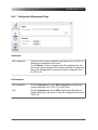
Configuration Management Page ................................................................................ 83
Application Programming Interface (API) ................................................................ 84
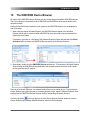
10 The OMICRON Device Browser ................................................................................. 85
4
TICRO 100 User Manual
10.1
Installing the OMICRON Device Browser ................................................................. 86
10.2
Finding OMICRON Devices in the Device Browser Manually (OMFind) ............... 86
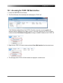
10.3
Accessing the TICRO 100 Web Interface ................................................................. 87
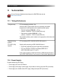
11 Technical Data ............................................................................................................ 88
11.1
Timing Performance .................................................................................................. 88
11.2
Power Supply ............................................................................................................. 88
11.3
Frequency Outputs and Time Codes ....................................................................... 90
11.4
Networking and Management ................................................................................... 92
11.5
Environmental Conditions ........................................................................................ 93
11.6
Mechanical Specifications ........................................................................................ 93
11.7
Electromagnetic Compatibility (EMC), Safety, Certificates .................................... 94
11.8
Compliance Statements ............................................................................................ 95
11.9
Cleaning ...................................................................................................................... 96
12 Open Source Software License Information ............................................................ 97
13 Glossary ...................................................................................................................... 98
Support ........................................................................................................................100
Index .............................................................................................................................101
5
TICRO 100 User Manual
Preface & General Safety Instructions
This user manual provides information about the TICRO 100, its possible fields of application and how
to install and operate it. Furthermore, it provides information how to access and configure the device
using a computer.
Following the instructions given in this user manual will help you to avoid danger, repair costs and
down time, and will help to maintain the reliability and life of the TICRO 100.
General safety instructions
Before operating the TICRO 100, carefully read the following general safety instructions:
•
The TICRO 100 may only be used in a safe technical condition taking into account its defined
purpose, safety requirements and possible risks as well as the operating instructions given in this
user manual!
•
The TICRO 100 is exclusively intended for the application areas specified in chapter Introduction
and Designated Use on page 7. The manufacturer or the distributors are not liable for damage
resulting from unintended usage. The user alone assumes all responsibility and risks.
•
The instructions provided in this manual are considered part of the rules governing proper usage.
•
Do not open the TICRO 100! Opening the device invalidates all warranty claims!
•
Do not carry out any modifications or adaptations to the TICRO 100.
•
Do not use any other power supply options for the TICRO 100 than the ones described in chapter
Power Supply on page 21.
•
The TICRO 100 is a SELV device (Safety Extra Low Voltage) which can be supplied with power by
Power over Ethernet (PoE class 3 powered device according to IEEE 802.3af). The ETH network
port of the TICRO 100 may only be connected to Ethernet network ports or Power over Ethernet
power supplies.
•
The FIBER network port and outputs 4 and 5 are products of laser class 1 (IEC 60825).
All inputs and outputs of the TICRO 100 are electrically connected to the SELV (safety extra
low voltage) insulation group of the device. It is not permitted to connect any voltages that
are not SELV compliant.
6
Introduction & Designated Use
1
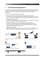
Introduction & Designated Use
The TICRO 100 is a Precision Time Protocol (PTP) time converter that allows you to derive a high
variety of time codes from IEEE 1588/PTP packages received via Ethernet. This device enables you
to easily synchronize non-PTP equipment to the grandmaster clock of an IEEE 1588/PTP
infrastructure.
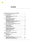
The TICRO 100 is designed for the following applications:
•
Generation of PTP-synchronized signals to make existing equipment PTP capable
The TICRO 100 can be used to generate several time synchronization signals (e.g., PPX, IRIG-B,
DCF77, etc.) required for existing equipment (e.g., IEDs) from an IEEE 1588/PTP infrastructure.
•
Synchronization of measurements
The TICRO 100 provides programmable trigger functionality that can be used for example to start
measurements at different locations at exactly the same time.
•
Generation and distribution of 10 MHz reference frequency signals over Ethernet
The TICRO 100 provides a highly accurate 10 MHz reference signal that can be used to
synchronize measurement equipment such as synthesizers, frequency counters or spectrum
analyzers to the same frequency reference signal.
•
Portable time code generation
Together with a portable PTP grandmaster clock (e.g., the OTMC 100 from OMICRON Lab), the
TICRO 100 can be used to perform quick time synchronized measurements in the field.
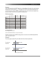
IED
1PPx
IEEE 1588/PTP
IED
Measurement
IRIG-B
Example: Generation of PTP-synchronized signals for existing
equipment
Example: Synchronization of measurements
10 MHz
IEEE 1588/PTP
1 PPx
IRIG-B
DCF77
10 MHz
Example: Generation of 10 MHz reference frequency
Key:
Measurement
= PTP grandmaster clock
Example: Portable time code generation
= TICRO 100
7
TICRO 100 User Manual
Features supported by the TICRO 100:
•
•
•
8
Timing features:
•
PTP time stamping resolution 8 ns
•
Internal oscillator hold-over functionality to bridge up to 24 hours of PTP synchronization loss.
(Oscillator options with different accuracies available.)
•
PTPv2 according to IEEE 1588-2008.
Supported profiles: Default profile according to IEEE 1588-2008 and Power profile acc. to
IEEE C37.238-2011.
Power supply options:
•
Power supply by Power over Ethernet PoE (class 3 powered device according to IEEE 802.3af,
max. power consumption < 13 W).
•
Power supply by the delivered plug-in power supply unit and/or by any other 18 ... 57 VDC
power supply (details and restrictions, see chapter Power Supply on page 21). Power supply
redundancy possible.
•
If powered by an external power supply mentioned above, the TICRO 100 is able to operate as
a power sourcing equipment (PSE) according to IEEE 802.3af. The device is then able to power
a class 1 device via its 100BaseTX Ethernet port (e.g. an OTMC 100 that is directly connected
to the TICRO 100).
Networking:
•
10/100Base-TX (twisted-pair) or 100Base-FX (optical fiber) Ethernet
•
IPv4 and IPv6
•
DHCP/Autoconf
•
Zeroconf (mDNS/DNS-SD)
•
OMICRON OMFind service
Introduction & Designated Use
•
•
•
Outputs and output signals
•
3 BNC connectors (50 Ω), 2 optical ST connectors, 1 optocoupler output
•
Possible output signals:
•
PPX: 1, 10, 100 or 1000 PPS (pulses per second), 1 PPM (pulse per minute), 1 PPH (pulse
per hour) or any pulse rate between 1 pulse per second and 1 pulse per day
•
IRIG-B (unmodulated and modulated on 1 kHz carrier)
•
DCF77 unmodulated
•
Trigger: 1 trigger pulse at a specific point in time or PPX pulse sequence starting at a
specific point in time
•
10 MHz sine wave
Configuration:
•
Can be accessed with a computer via Ethernet or USB
•
Web Interface (HTTP & HTTPS) with optional password protection
•
Automated configuration via SSH, SOAP and XML files
Linux operating system:
•
TFTP, FTP and SSH access
•
Syslog (local and remote)
•
E-Mail notifications
•
Failsafe software upgrades in the field
•
Installation options:
•
Permanent indoor installation on DIN rail or by wall mounting.
•
Portable use in dry environments.
The TICRO 100 is exclusively intended for the applications stated in this chapter. Any other use is
considered improper.
9
TICRO 100 User Manual
2
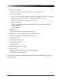
Scope of Delivery, Ordering Information, Accessories
Description
Part No.
TICRO 100 PTP TimeConverter.
OL000310 for
TICRO 100 with
OCXO-100 option
The delivered box includes:
•
1 TICRO 100 device
•
1 plug-in power supply unit
•
1 power connector MC 1.5/2-STF-3.81
(two-pin power connector for external DC
power supply)
•
1 terminal block for optocoupler output
MSTB 2,5 HC/ 2-STF-5,08
10
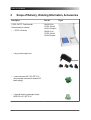
OL000311 for
TICRO 100 with
OCXO-25 option
Figure
Scope of Delivery, Ordering Information, Accessories
•
1 DIN rail mounting clip (Hutsclip/AL/0009)
for mounting on 35 mm DIN rail according
to IEC 50022 incl. 2 M3x12 screws (TX10)
•
1 Wall mounting kit AB-WL 3
•
1 TICRO 100 Quick Start Guide (printed)
•
1 CD ROM containing the OMICRON
Device Browser software, the PDF versions
of the TICRO 100 Series User Manual and
the TICRO 100 Series Quick Start Guide,
and the source code of the Open Source
products used in the TICRO 100 software
11
TICRO 100 User Manual
3
Device Description
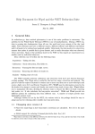
3.1
Device Overview
10/100Base-TX
twisted-pair Ethernet port
Status LEDs and
output status LEDs
LEDs indicating the
active Ethernet port
Device status LEDs
S1 & S2
DC power input
(18 ... 57 VDC)
USB connector
(USB 2.0 type B)
10 MHz output
50 W BNC socket
Output 1 and 2
50 W BNC socket
Output 3
Optocoupler
output
Output 4 and 5
Optical outputs
ST connector, 820 nm
100Base-FX
optical fiber Ethernet port
DC power input for
plug-in-power supply unit
Mounting wholes for
wall mounting brackets
(covered by sealing plug)
DIN rail clip
Type plate with serial number
on bottom side
Reset pushbutton
The TICRO 100 does not provide an ON/OFF switch! The device automatically powers up after supply
voltage is provided via one of the DC power inputs or via Ethernet (PoE).
Refer to the following subsections for detailed information about the LEDs, connectors and operating
elements of the TICRO 100.
12
Device Description
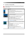
3.2
LEDs on the Front Side
LED
Description
S1 and S2
Green and red LED indicating the general device status according to the following
code.
S1 (green)
S2 (red)
Meaning
off
off
TICRO 100 not is supplied with power or device reboot is
requested.
off
on
Device is booting (normal boot process after applying
supply voltage or after reboot).
on
off
The TICRO 100 is ready for operation (boot process
finished and device is operational). Observe the other
LEDs for information about the PTP clock status, the
status of the Ethernet connection and the output states.
on
on
Device is booting in recovery mode. Intermediate state
when entering the recovery mode manually or when
initiating a factory reset (see Operating Procedures
Performed Directly on the Device on page 34).
blinking
off
Device is in recovery mode, waiting for new software. In
the recovery mode, the device provides only a
rudimentary Web Interface just allowing for the upload of
a software image (see Operating Procedures Performed
Directly on the Device on page 34).
off
blinking
Software update is in progress.
Do not disconnect the TICRO 100 from the
power supply or from the Ethernet or USB
connection during a software update.
blinking
RJ45 and
FIBER
blinking
Hardware error.
Green LEDs to indicate the currently active Ethernet port:
RJ45 for 10/100Base-TX (twisted-pair) or FIBER for 100Base-FX (optical fiber).
Only one Ethernet port can be used at a time. The Ethernet port actually
used has to be selected in the Web Interface (see section Network
Configuration Page on page 68).
13
TICRO 100 User Manual
LED
Description
LEDs on the
Ethernet
connectors
The green LED indicates the Ethernet connection status (link status). The yellow
LED indicates that data traffic is active on the interface.
Status L and H
Green LEDs to indicate the PTP status of the device:
L: Indicates the locked state. The TICRO 100 receives PTP time information from
a PTP grandmaster clock and is locked to this signal. It is able to provide its
defined accuracy. The TICRO 100 is synchronized to the received PTP time
signal.
The LED starts blinking as soon as the TICRO 100 has established connection to
a PTP grandmaster clock and started its locking algorithm. As soon as an
accuracy of better than 1 µs is reached, the LED stops blinking. The typical overall
accuracy (better than 200 ns) is reached after approximately 15 minutes.
However, please note that the absolute overall system accuracy depends on the
accuracy of the PTP grandmaster clock and the PTP compliance of the network
infrastructure.
H: Indicates the hold-over state. If the TICRO 100 was in the locked state before,
it enters the hold-over state when it loses synchronization to the PTP time signal.
If configured in the output configuration, the TICRO 100 continues to output time
signals during the hold-over state. However, these output signals are now derived
from the internal oscillator (OCXO) instead of the PTP time signal. The maximum
duration for the hold-over state is 24 hours. If the TICRO 100 was less than 48
hours in the locked state before loosing the PTP signal, the maximum duration for
the hold-over state is half the "locked" time.
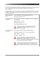
Status M and S
M: LED for future use. Currently without function.
S: Indicates that the TICRO 100 receives a PTP signal, is connected to a PTP
grandmaster, and has taken over the role of a slave clock.
Output 1 to 5
Green LEDs to indicate which outputs are currently active.
Outputs can be disabled or muted in the Web Interface or automatically
deactivated by the TICRO 100 if it is not able to provide time signals with sufficient
accuracy. For more detailed information, please refer to section Output
Configuration Page on page 58.
14
Device Description
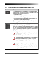
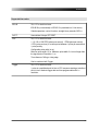
3.3
Connectors on the Front Side
All inputs and outputs of the TICRO 100 are electrically connected to the SELV (safety extra
low voltage) insulation group of the device. It is not permitted to connect any voltages that
are not SELV compliant.
Connector
Description
10 MHz output (50 Ω BNC socket).
This output provides a highly accuracte 10 MHz sine wave signal
(4 dBm ± 2 dB at 50 Ω). The 10 MHz output is always active and cannot be
configured in the Web Interface.
Output 1 and 2 (50 Ω BNC socket).
Outputs 1 and 2 can be configured in the Web Interface for the following
signals:
- IRIG-B, unmodulated TTL signal or modulated on 1 kHz carrier
- PPX (TTL signal, 1000 pulses per second to 1 pulse per day)
- DCF77 unmodulated TTL signal
- Trigger (TTL signal, 1 pulse at a defined point in time)
- Trigger (TTL signal, PPX sequence starting at the defined point in time)
For information about configuring these outputs, please refer to section
Output Configuration Page on page 58.
Output 3 (optocoupler output 30 V/100 mA max., terminal block supplied on
delivery).
Output 3 can be configured in the Web Interface for the following signals:
- IRIG-B unmodulated
- PPX (1000 pulses per second to 1 pulse per day)
- DCF77 unmodulated
- Trigger (1 pulse at a defined point in time)
- Trigger (PPX sequence starting at the defined point in time)
For information about configuring this output, please refer to section Output
Configuration Page on page 58.
15
TICRO 100 User Manual
Optical output 4 and 5 (ST connector, 820 nm).
Outputs 4 and 5 can be configured in the Web Interface for the following
signals:
- IRIG-B unmodulated
- PPX (1000 pulses per second to 1 pulse per day)
- DCF77 unmodulated
- Trigger (1 pulse at a defined point in time)
- Trigger (PPX sequence starting at the defined point in time)
For information about configuring these outputs, please refer to section
Output Configuration Page on page 58.
RJ45: 10/100Base-TX twisted-pair Ethernet port (RJ45 socket).
FIBER: 100Base-FX optical fiber Ethernet port (ST connector, 820 nm).
The LEDs indicate the link status and the data traffic.
The TICRO 100 can use only one Ethernet port at a time.
If no Ethernet port is selected in the Web Interface, the RJ45
Ethernet port is the default port if the TICRO 100 does not detect
an operating Ethernet network on any of the network ports during
the first power-up or after a factory reset. It is strongly
recommended to set the network port in the Web Interface
manually during commissioning (see section Network
Configuration Page on page 68).
USB port (USB 2.0, type B). Use this interface as an alternative for
connecting a computer to the TICRO 100 if access to the Web Interface is
not done via the Ethernet network.
When accessing the TICRO 100 Web Interface via the USB port,
you should take care that the computer is not connected to the
Ethernet network the TICRO 100 is connected to. The computer
must not be connected to the TICRO 100 over the Ethernet
network and the USB port at the same time!
16
Device Description
DC power input socket (MC 1.5/2-STF-3.81, connector supplied on delivery).
The correct polarity is printed on the front plate.
You can use this connector to connect a 18 ... 57 VDC supply voltage, either
as an alternative to the plug-in power supply unit supplied on delivery (DC
power input socket on rear side) or in addition to the plug-in power supply
unit to provide power supply redundancy for the TICRO 100. For more
details, please refer to chapter Power Supply on page 21.
The used power supply unit must comply with the SELV standard if
product safety according to IEC 61010-1 and IEC 60255-27 is
required.
The DC power inputs of the TICRO 100 are protected against
polarity reversal if only one input is used at a time. When using
both DC power inputs, make sure to observe the correct polarity
for both inputs. Reversed polarity on one of the DC power inputs
would make the reverse polarity protection ineffective and could
damage the TICRO 100.
17
TICRO 100 User Manual
3.4
Connectors and Operating Elements on the Rear Side
Element
Description
The reset pushbutton can be accessed through the hole in the rear panel
using a thin pointed object like a wired resistor with a diameter < 0.9 mm, for
example. The reset pushbutton can be used to:
•
Initiate a device reboot.
•
Initiate a factory reset to reset the device configuration to the factory
defaults (for example, if you forgot your password).
•
Enter the recovery mode in order to upload software to the device (for
example, after a software update process failed).
Please refer to section Operating Procedures Performed Directly on the
Device on page 34 for more detailed descriptions.
DC power input socket (standard DC barrel jack 2.5 x 5.5 x 11 mm, center
pin positive). Permitted voltage range: 18 ... 57 VDC
Use this input to connect the plug-in power supply unit supplied on delivery if
the TICRO 100 is not supplied via Power over Ethernet (PoE). You can also
use the DC power input on the front side as a second DC source in addition
to this DC power input to provide power supply redundancy for the
TICRO 100. For more details, please refer to chapter
Power Supply on page 21.
This DC power input socket does not fulfill the surge requirements
of IEC 60255-27. Use the DC power input socket on the front side
if IEC 60255-27 compliance is required.
The used power supply unit must comply with the SELV standard if
product safety according to IEC 61010-1 and IEC 60255-27 is
required. The plug-in power supply unit supplied on delivery
complies with the SELV standard.
The DC power inputs of the TICRO 100 are protected against
polarity reversal if only one input is used at a time. When using
both DC power inputs, make sure to observe the correct polarity
for both inputs. Reversed polarity on one of the DC power inputs
would make the reverse polarity protection ineffective and could
damage the TICRO 100.
18
Mounting
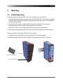
4
Mounting
4.1
DIN Rail Mounting
Proceed as follows to mount the TICRO 100 to a 35 mm DIN rail (acc. to EN 50022):
1. Place the DIN rail clip supplied on delivery to the rear side of the TICRO 100 as shown in the figure
below and align it with the mounting holes. The spring side of the DIN rail clip must point towards
the DC power input socket!
2. Use the two M3x12 screws to fasten the DIN rail clip to the TICRO 100 (TX10 screwdriver
required). Do not use other screws than delivered with the DIN rail clip!
3. Hook in the TICRO 100 with the spring side of the clip at the top side of the DIN rail.
4. Press the device downwards and then to the DIN rail until the clip audibly snaps onto the DIN rail.
Proceed as follows to remove the TICRO 100 from the DIN rail:
1. Compress the spring of the DIN rail clip by pressing the TICRO 100 downwards.
2. Release the bottom side of the clip from the DIN rail and withdraw the TICRO 100 upwards.
DIN rail clip with screws
DC power input socket
19
TICRO 100 User Manual
4.2
Wall Mounting
A wall mounting kit with four mounting brackets is provided on delivery for mounting the TICRO 100 on
flat surfaces, for example on a wall.
Please observe the instructions included in the wall mounting kit for attaching the mounting brackets to
the TICRO 100. Proceed as follows:
•
At the desired mounting positions for the mounting brackets, remove two sealing plugs on the rear
side and two sealing plugs on the front side of the TICRO 100.
•
Unscrew the four uncovered screws from the TICRO 100.
•
Insert the four sealing rings included in the mounting kit to the mounting holes of the TICRO 100.
•
Fasten the mounting brackets using the delivered 22 mm long screws as shown below.
•
Mount the TICRO 100 to the wall.
Remove 2 sealing plugs from the
mounting holes on the front side
Remove 2 sealing plugs
from the mounting holes
on the rear side
Wall mounting kit
20
TICRO 100 with mounting brackets
Power Supply
5
Power Supply
The TICRO 100 does not provide an ON/OFF switch! The device automatically powers up after supply
voltage is applied.
There are three possibilities to supply the TICRO 100 with power:
1. Power supply via Power over Ethernet (PoE).
2. Power supply via the plug-in power supply unit provided on delivery.
3. Power supply via any suitable external DC supply voltage.
You can supply the TICRO 100 using only one of these power supply options or using a combination
of two or all three options to provide power supply redundancy. When supplied by two external power
supplies (options 2. and 3. above), the TICRO 100 automatically switches to the other source without
any interruption if one power source fails. If supplied via PoE and an external power supply (option 1.
and 2. or option 1. and 3.), the TICRO 100 will reboot after switching from the external power supply
(option 2. or 3.) to PoE power supply (option 1.).
As long as supply voltage is applied to only one of the DC power input sockets, the DC
power inputs of the TICRO 100 are protected against polarity reversal. When using both DC
power input sockets at the same time, make sure to observe the correct polarity for both
inputs. Reversed polarity on one of the DC power inputs would make the reverse polarity
protection ineffective and could damage the TICRO 100.
If powered via the delivered plug-in power supply unit or by an external DC supply voltage,
the TICRO 100 is able to operate as a power sourcing equipment (PSE) for class 1 devices
according to IEEE 802.3af.
5.1
Power Supply via Power Over Ethernet
The easiest method for supplying the TICRO 100 with power is via Power over Ethernet (PoE)
according to IEEE 802.3af. Power supply via PoE does not require any additional cabling since it uses
the same cable (RJ45 port) for Ethernet communication and power supply.
Power supply via PoE is not possible if you are using an optical fiber Ethernet network.
The Ethernet network port used to supply the TICRO 100 (i.e., the network port the TICRO 100 is
connected to) must be able to supply a class 3 powered device (power consumption < 13 W).
If no suitable PoE source (e.g., an Ethernet switch) is available, it is also possible to use a suitable
PoE injector which is connected between the Ethernet port on the network side and the Ethernet port
of the TICRO 100. A PoE injector is not included in the scope of delivery.
21
TICRO 100 User Manual
5.2
Power Supply via the Delivered Plug-In Power Supply Unit
Connect the plug-in power supply unit provided on delivery to the DC power input socket (standard DC
barrel connector) on the rear side of the TICRO 100.
When connecting another power supply unit than the delivered one to this DC power input socket,
please observe the correct polarity (center pin is positive). The used power supply unit must deliver a
voltage of 18 ... 57 VDC with an output power of at least 13 W.
The DC power input socket on the rear side does not fulfill the surge requirements of
IEC 60255-27. Use the DC power input socket on the front side if IEC 60255-27 compliance
is required.
The used power supply unit must comply with the SELV standard if product safety according
to IEC 61010-1 and IEC 60255-27 is required. The plug-in power supply unit supplied on
delivery complies with the SELV standard.
5.3
Power Supply via an External DC Supply Voltage
The TICRO 100 can also be supplied by an external DC supply voltage using the DC power input
socket on the front side. A corresponding two-pin connector (MC 1.5/2-STF-3.81) is provided on
delivery. The correct polarity is printed on the front plate.
The DC supply voltage must be in a range of 18 ... 57 V and deliver a power of at least 13 W.
The used power supply unit must comply with the SELV standard if product safety according
to IEC 61010-1 and IEC 60255-27 is required.
5.4
Using the TICRO 100 as a PoE Power Source According to
IEEE 802.3af
If powered via the delivered plug-in power supply unit or by an external DC supply voltage as
described in the sections above, the TICRO 100 is able to operate as a power sourcing equipment
(PSE) according to IEEE 802.3af. The device is then able to power a class 1 device via its 100BaseTX
Ethernet port. This becomes especially handy if you operate the TICRO 100 with the antennaintegrated PTP grandmaster clock OTMC 100 from OMICRON Lab.
22
Accessing the Web Interface & Initial Setup
6
Accessing the Web Interface & Initial Setup
The TICRO 100 automatically powers up after supply voltage is applied. The green LED S1 lights up
and the red LED S2 is off when the device is ready for operation.
The TICRO 100 can be configured and controlled completely via the Web Interface using a computer.
Under normal circumstances, no manual intervention at the device itself will be required.
6.1
System Requirements
Your computer must fulfill the following requirements to access the TICRO 100 Web Interface:
•
OMICRON Device Browser installed (see chapter The OMICRON Device Browser on page 85).
The OMICRON Device Browser is always required for the initial access to the TICRO 100.
If a fixed IP address is assigned to the TICRO 100, the device can be accessed any time
and from any computer using this IP address.
•
Web browser installed (Windows Internet Explorer 10 or higher, Mozilla Firefox 20 or higher, or
Google Chrome version 31 or higher).
•
For access via Ethernet network only:
Network port configured for operation in the network the TICRO 100 is connected to.
•
For access via USB only:
USB 2.0 port available. While accessing the TICRO 100 via USB, the computer must not be
connected to the same Ethernet network the TICRO 100 is connected to!
If you are accessing the TICRO 100 from a Mac or Linux operating system supporting
zeroconf, you can access the Web Interface of the TICRO 100 by entering
http://<hostname>.local to the address bar of your web browser. The default hostname is
the device serial number. The serial number is available on the type plate on the bottom side
of the TICRO 100 (labeled "SerNo").
6.2
Accessing the TICRO 100 Web Interface
The OMICRON Device Browser is required for the initial access to the TICRO 100. If you
know the IP address of the TICRO 100, it is also possible to access the device from a web
browser using this IP address (without using the OMICRON Device Browser).
Proceed as follows to access the TICRO 100 Web Interface:
1. Connect your computer to the network or the USB port of the TICRO 100.
23
TICRO 100 User Manual
2. If necessary, install the OMICRON Device Browser on your computer. See chapter The OMICRON
Device Browser on page 85.
3. Launch the OMICRON Device Browser.
4. The Device Browser will automatically find and display the TICRO 100.
If the IP address configurations of the TICRO 100 and the computer are not compatible, the
respective status is displayed in the Status column. In this case, right-click the TICRO 100 serial
number and select Set Network Configuration to assign a suitable IP address to the TICRO 100.
5. Right-click the TICRO 100 serial number and select Open Web Interface from the context menu.
24
Accessing the Web Interface & Initial Setup
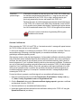
6. The Web Interface is opened in a web browser.
Password protection is disabled by default. If a password has been defined for the TICRO 100, a
login dialog is displayed. Enter your password and click Login. The default password is
timeterminal.
7. The start page of the TICRO 100 Web Interface is displayed. You can now access all pages of the
Web Interface.
•
Proceed with section Next Steps to Set Up the TICRO 100 on page 26 in order to configure
the TICRO 100 according to your needs.
•
Use the Logout link in the top right corner to exit the TICRO 100 Web Interface.
25
TICRO 100 User Manual
6.3
Next Steps to Set Up the TICRO 100
After connecting the TICRO 100 to the network and accessing the device from your computer, you
have to configure the TICRO 100 according to your needs.
See chapter The TICRO 100 Web Interface on page 37 or the TICRO 100 help for a detailed
description of the Web Interface, or section Operating Procedures Performed via the Web
Interface on page 28 for a description of the most important operating procedures.
Proceed as follows to set up and configure your TICRO 100. Consult your network administrator if you
do not know the correct settings.
1. Configure the network settings.
Open the Configuration section of the Web Interface and display the Network page (see page
68). Select your configuration and click the Save button to save and apply your settings.
•
Select the network interface and configure the network/IP settings according to the needs of
your network.
By default, the TICRO 100 will attempt to get an IPv4 address via DHCP and assign an
IPv6 address using the automatic configuration. If no DHCP server is available for IPv4,
the TICRO 100 uses the zeroconf service to automatically assign an own IP address.
2. Configure the PTP settings.
Display the PTP page of the Configuration section (see page 64). Select your configuration and
click the Save button to save and apply your settings. The most important PTP settings are:
a. PTP profile (General tab):
•
Select the PTP profile used in your network (Default E2E, Default P2P or Power systems).
•
Select the maximum permitted inaccuracy of the PTP grandmaster. The TICRO 100 enters
the hold-over state if the inaccuracy of the actual PTP grandmaster exceeds this value.
b. Domain number (Default tab): All PTP devices that should synchronize to the same
grandmaster clock must use the same domain number.
3. Configure the output settings.
Display the Output page of the Configuration section (see page 58). Select your configuration
and click the Save button to save and apply your settings.
26
•
Configure the outputs according to your needs. A separate tab is available for each output.
•
In the Outputs active field of the Clock settings pane you can configure the TICRO 100 to
automatically deactivate its outputs if it is not able to provide time signals with sufficient
accuracy. The outputs can be always active, only active when the TICRO 100 is locked to a
PTP signal or only active when the TICRO 100 is locked to a PTP signal or in the hold-over
state.
•
Use the Current time zone field of the Clock settings pane to set the time zone of the location
where you are using the TICRO 100.
Accessing the Web Interface & Initial Setup
4. If desired, secure your TICRO 100 against unauthorized access.
Display the Security page of the Configuration section (see page 75). Select your configuration
and click the Save button to save and apply your settings.
a. Display the Access Control tab and set the Access field to "Password".
If you set the Access field to "Password" without defining a password, the default
password timeterminal will be used.
b. Enter a password to the Change Password field and repeat your password in the Confirm
Password field. Click the Change button to save and apply your settings. From now on,
entering the password is required to access the TICRO 100.
c. In the Protocol field, select whether you want to allow access via the secure HTTPS protocol
only or via HTTPS and the unsecure HTTP protocol.
By default, password transmission to the TICRO 100 is performed unencrypted. By selecting
HTTPS only you can force the use of the encrypted HTTPS protocol and thus protect your
password.
When accessing the TICRO 100 via HTTPS, an "untrusted connection" message
may appear because the TICRO 100 does not have a valid certificate. To avoid
such messages, it is necessary to provide the TICRO 100 with such a certificate.
Please refer to subsection "Generate Certificate tab" in section Security
Configuration Page on page 75 for more detailed information.
d. In the Services field, select whether you want to allow access to the TICRO 100 via the Web
Interface (Web) or the Application Programming Interface API (SOAP) only or via both
interfaces (Web and SOAP).
e. Protocol restrictions: Disabling services that are not required or used for operation will
minimize potential points of attack and thus make the TICRO 100 safer.
•
Usually the OMICRON Device Browser is used to find the TICRO 100 in the network.
However, the OMICRON Device Browser may also be used to change the network
configuration of the TICRO 100. To protect your TICRO 100 against unauthorized or
unintentional configuration changes using the OMICRON Device Browser, deselect the
Allow OMFIND network configuration option.
•
If you want to prohibit standard user/password authenticated access to the TICRO 100 via
secure shell (SSH), deselect the Allow SSH password login option. When deselected,
access via SSH is only possible via key based authentication. This reduces the risk of
unauthorized access to the TICRO 100 through brute force attacks.
The options in the Protocol Restrictions tab of the Security page just enable or
disable protocol options. In order to completely disable a service, use the Services
pane of the Network configuration page.
27
TICRO 100 User Manual
7
Operating the TICRO 100
The following sections describe the most important operating procedures for the TICRO 100.
Please refer to chapter The TICRO 100 Web Interface on page 37 or the Web Interface help for a
detailed description of the Web Interface.
7.1
Operating Procedures Performed via the Web Interface
The following subsections describe the most important operating procedures that can be performed
via the Web Interface using a computer. In order to operate the TICRO 100 via the Web Interface,
access the device from a computer as described in section Accessing the TICRO 100 Web
Interface on page 23.
28
Operating the TICRO 100
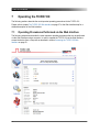
7.1.1
Displaying Status Information
1. The overall status information (output states, general device status and network status) are
displayed in the Overview section of the Web Interface.
2. To display more detailed status information, access the Status section by clicking the
corresponding icon in the navigation bar of the Web Interface.
3. Click the Output, PTP or Network icon of the Status section to display the corresponding status
page (see page 42) .
7.1.2
Configuring the Outputs
A short overview of the output states is provided in the Overview section of the Web Interface. The
overview also provides hyperlinks to directly access the output configuration. The 10 MHz output is
always active and cannot be configured in the Web Interface.
Please refer to section Output Configuration Page on page 58 for detailed information about the
possible output signal modes.
1. Click the Configuration icon in the navigation bar of the Web Interface.
2. Click the Output icon of the Configuration section and display the tab of the output to be
configured.
3. Configure the output(s) according to your needs.
4. Use the Outputs active field in the Clock Settings pane to select whether the TICRO 100 should
automatically deactivate its outputs if it is not able to provide time signals with sufficient accuracy.
The outputs can be always active, only active when the TICRO 100 is locked to a PTP signal, or
only active when the TICRO 100 is locked to a PTP signal or in the hold-over state.
5. Use the Current time zone field of the Clock settings pane to set the time zone of the location
where you are using the TICRO 100.
6. Click the Save button to save and apply your output configuration to the TICRO 100.
7.1.3
Defining a Password
If no password is defined for accessing the TICRO 100, a corresponding note is displayed on the
Overview page providing the possibility to directly access the security configuration (see page 75) in
order to enable password protection.
1. Click the Configuration icon in the navigation bar of the Web Interface.
2. Click the Security icon of the Configuration section and display the Access Control tab.
29
TICRO 100 User Manual
3. Enter your password to the Change password field and repeat it in the Confirm password field.
The password is case sensitive and must have at least 5 characters (letters, figures or
special characters).
4. In the Access field, select Password to activate password protection.
If you set the Access field to Password without defining a password, the default
password timeterminal will be used.
5. In the Protocol field, select whether you want to allow access via the secure HTTPS protocol only
or via HTTPS and the unsecure HTTP protocol.
By default, password transmission to the TICRO 100 is performed unencrypted. By selecting
HTTPS only you can force the use of the encrypted HTTPS protocol and thus protect your
password.
6. In the Services field, select whether you want to allow access to the TICRO 100 via the Web
Interface (Web) or the Application Programming Interface API (SOAP) only or via both interfaces.
7. Click the Save button.
8. Your new password is applied to the TICRO 100 and the login dialog appears.
For more information, please refer to section Security Configuration Page on page 75.
Perform a factory reset on the device if you forgot your password (see section Operating
Procedures Performed at the Device on page 34).
7.1.4
Setting the Time Manually
Setting the time manually is only required and possible if the TICRO 100 does not receive time with
sufficient accuracy via PTP. The manual time settings are overwritten by the PTP time information as
soon as the TICRO 100 locks to a PTP signal.
Please refer to section Device Control Page on page 80 for more detailed information about leap
seconds and time setting.
1. Click the Tools icon in the navigation bar of the Web Interface.
2. Click the Device Control icon.
3. Click the New Time (UTC) field to open a calendar dialog allowing for the selection of the current
date and time.
30
Operating the TICRO 100
4. Set the Leap seconds field to the actual offset of TAI to UTC (in 2013: 35 seconds; if necessary,
investigate on the Internet for the actual TAI-UTC offset valid at the time of reading).
If the TICRO 100 is locked to a PTP grandmaster, the leap seconds field is updated
automatically via PTP.
5. Click the Save button to save and apply your time settings to the TICRO 100.
7.1.5
Running a Software Update for the TICRO 100
1. Click the Tools icon in the navigation bar of the Web Interface.
2. Click the Software Update icon.
3. Click the Browse... button to navigate to the software image file and select it.
4. Deselect the Keep settings check box if you want to reset the device configuration to the factory
defaults after the software update. If the check box is selected, the user specific configuration
settings are kept during the software update.
5. Click the Update button to start the software update.
6. The update process may take several minutes. Do not unplug the DC power supply or disconnect
the Ethernet connection between the TICRO 100 and the computer during this process.
7. The TICRO 100 automatically restarts after the software update has completed.
If the software update process fails due to any reason, the TICRO 100 enters a recovery
mode on the next power-up. In this mode, the device provides only a rudimentary Web
Interface (similar to the Software Update page) just allowing for the upload of a software
image (see section Uploading New Software to the Device in Recovery Mode on page 32).
7.1.6
Performing a Reboot of the TICRO 100
A device reboot can also be performed directly on the device (see section Operating
Procedures Performed at the Device on page 34).
1. Click the Tools icon in the navigation bar of the Web Interface.
2. Click the Device Control icon.
3. Click the Reboot button next to Reboot device.
4. The TICRO 100 performs a reboot. The device will be ready for operation again after approximately
one minute.
31
TICRO 100 User Manual
7.1.7
Performing a Factory Reset (Reset to Factory Defaults)
A factory reset can also be performed directly on the device (see section Operating
Procedures Performed at the Device on page 34). Performing a factory reset may possibly
result in an IP address change of the TICRO 100 due to automatic IP address assignment by
a DHCP server.
1. Click the Tools icon in the navigation bar of the Web Interface.
2. Click the Device Control icon.
3. Click the Reset button next to Factory reset.
4. The TICRO 100 performs a reboot and resets all configuration settings to the factory defaults. The
device will be ready for operation again after approximately one minute.
7.1.8
Creating a System Snapshot for Troubleshooting
A system snapshot contains the configuration settings and the log file. It thus provides important
information for the technical support in case of problems.
1. Click the Tools icon in the navigation bar of the Web Interface.
2. Click the Device Control icon.
3. Click the Download button next to System snapshot to download a system snapshot file.
Downloading a system snapshot may take approx. 30 s to 1 minute.
7.1.9
Uploading New Software to the Device in Recovery Mode
Entering the recovery mode manually is only possible using the reset pushbutton on the
device (see section Operating Procedures Performed at the Device on page 34).
The recovery mode is entered automatically if a software update performed via the Web Interface fails.
1. In recovery mode the device provides a rudimentary Web Interface solely allowing for the upload of
a software image.
2. Click the Browse... button to navigate to a suitable software image file.
3. Click the Update button to start the software update.
4. The update process may take several minutes. Do not unplug the DC power supply or disconnect
the Ethernet connection between the TICRO 100 and the computer during this process.
5. The TICRO 100 automatically restarts after the software has installed completely.
32
Operating the TICRO 100
7.1.10 Assigning an IP Address Manually
The IP address of the TICRO 100 is usually assigned automatically. If a DHCP server is available in
the network, the IP address is assigned by the DHCP server. If not, the TICRO 100 automatically
selects and assigns an IP address on its own.
1. Click the Configuration icon in the navigation bar of the Web Interface.
2. Click the Network icon of the Configuration section and display the IPv4 tab (or IPv6 if the
network supports IPv6).
3. Select IPv4 static IP address in the Configuration field.
4. Enter the IP address, the Network mask, the Gateway address and the Name server address in
dot-decimal notation (e.g.: 192.168.1.100).
5. Click the Save button to upload and save your settings in the TICRO 100.
See also section Network Configuration Page on page 68.
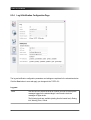
7.1.11 Viewing and/or Exporting the System Log File
The log file contains all events logged by the system. Therefore, it may be helpful for the
OMICRON Lab technical support in case of problems.
Which types of events are actually logged by the system can be selected in the Log & Notifications
configuration (see page 72) .
1. Click the Status icon in the navigation bar of the Web Interface.
2. Click the Log Viewer icon to display the log file.
3. View the messages logged in the file. Error messages are displayed in red, warning messages are
displayed in orange, notice messages are displayed in black. All other messages are displayed in
gray.
4. By clicking Clear View you can clear the display of the Log Viewer page. This does not clear the
log file. Re-opening the Log Viewer page will again display all messages logged in the log file.
5. By clicking Export Log you can export the log file content to a text file (file extension .log).
The log file is cleared with each reboot of the TICRO 100 (see section Performing a reboot of
the TICRO 100 on page 31 or Performing a reboot of the TICRO 100 on page 34). If the
maximum size of the log file is reached, the system automatically deletes old log file entries
in order to release memory space for new entries.
33
TICRO 100 User Manual
7.2
Operating Procedures Performed Directly on the Device
This section describes the operating procedures that can be performed directly at the TICRO 100
using the reset pushbutton. The reset pushbutton can be accessed through the hole in the rear panel
using a thin pointed object like a wired resistor with a diameter < 0.9 mm, for example.
LEDs S1 & S2
Reset pushbutton
7.2.1
Performing a Reboot of the TICRO 100
A device reboot can also be performed via the Web Interface (see section Performing a
reboot of the TICRO 100 on page 31).
1. Press the reset pushbutton and release it immediately.
2. The green LED S1 goes off for approx. 1 s.
3. LED S2 lights up red during the boot process.
4. After approx. 15 s, the red LED S2 goes off and the green LED S1 lights up.
5. The device rebooted successfully and is ready for operation.
7.2.2
Performing a Factory Reset (Reset to Factory Defaults)
A factory reset can also be performed via the Web Interface (see section Performing a
factory reset on page 32).
Performing a factory reset may possibly result in an IP address change of the TICRO 100
due to automatic IP address assignment by a DHCP server.
34
Operating the TICRO 100
Resetting the device to the factory defaults may be necessary if you forgot your password or if you
cannot access the TICRO 100 Web Interface anymore because you selected the wrong Ethernet
network port by mistake before.
1. Press the reset pushbutton and keep it pressed.
2. The green LED S1 goes off.
3. After approx. 5 s, the red LED S2 lights up together with the green LED S1. Keep the button
pressed and wait until the green LED S1 goes off (the red LED S2 is still on).
4. Release the reset pushbutton.
5. After approx. 15 s, the red LED S2 goes off and the green LED S1 lights up.
6. The device rebooted successfully and has now the factory default configuration settings.
7.2.3
Entering the Recovery Mode Manually (and Uploading New Software to
the TICRO 100)
Entering the recovery mode manually is not necessary under normal circumstances. This is only
necessary if a software update initiated via the Web Interface failed.
1. Press the reset pushbutton and keep it pressed.
2. The green LED S1 goes off for approx. 5 s.
3. Release the reset pushbutton as soon as the green LED S1 lights up together with the red LED S2.
4. After approx. 30 s the green LED S1 flashes to indicate the recovery mode.
5. Open the OMICRON Device Browser and right-click the TICRO 100 (see section Accessing the
TICRO 100 from a Computer on page 23). Select the Upgrade Device option from the context
menu. The device provides a rudimentary Web Interface allowing for an upload of a software
image.
6. Click the Browse... button to navigate to a suitable software image file. The path and file name is
displayed in the field after selecting it in the file open dialog.
35
TICRO 100 User Manual
7. Click the Update button to start the software update. The update process may take several
minutes. Do not disconnect the TICRO 100 or the computer during this process. The TICRO 100
automatically restarts after the software has installed completely.
36
The TICRO 100 Web Interface
8
The TICRO 100 Web Interface
The Web Interface is used to access and configure the TICRO 100 with a computer.
Click the help icon
in the top right corner of a page to display the specific help topic for
this particular page. Click Help in the top right corner of the Web Interface to open the start
page of the help system for the Web Interface.
37
TICRO 100 User Manual
Click Support in the top right corner to open the contact information page providing OMICRON Lab
contact addresses and information how to contact the technical support of OMICRON Lab in case of
problems.
Click Manual in the top right corner to open this manual in PDF format.
Click Logout in the top right corner to exit the TICRO 100 Web Interface.
Click License Information in the bottom right corner to view copyright and license information
regarding open source products used in the TICRO 100 software.
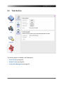
The Web Interface is divided into four main sections. Click an icon in the navigation bar on the left to
access the content of the corresponding section.
Overview (see page 39)
This section provides an overview of the current settings and states of the
TICRO 100.
Status (see page 42)
The Status section provides detailed information about the current states and
settings of the outputs, the PTP status and the network status. An additional
Log Viewer page shows all events logged in the internal log file.
Configuration (see page 57)
Use the Configuration section to configure the device settings (outputs,
clock, PTP, network and security settings). You can furthermore configure the
event logging and the e-mail notification function of the TICRO 100.
Tools (see page 79)
Use this section to perform a software upgrade for the TICRO 100 or to
perform a reboot or a factory reset of the device. You can furthermore upload
or download the device configuration, or download a system snapshot
containing important information for the technical support in case of problems.
38
The TICRO 100 Web Interface
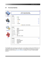
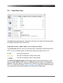
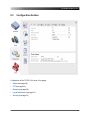
8.1
Overview Section
The Overview section provides an overview of the current settings and states of the TICRO 100. If no
password for accessing the TICRO 100 is defined, a corresponding note is displayed providing the
possibility to directly access the security configuration (see page 75) in order to enable password
protection.
39
TICRO 100 User Manual
Some elements provide an edit hyperlink. Click this hyperlink to directly open the
corresponding configuration page (see page 57) .
The following information is displayed in the Overview section.
Output pane
Displays the configuration of each output (IRIG-B, PPX, DCF77, etc.) and if the output is active or not:
Green LED: Output active
Gray LED, text displayed in orange: Output muted
Gray LED, text displayed in black: Output disabled
The 10 MHz BNC output is always active as soon as the TICRO 100 is ready for operation.
If the TICRO 100 is not in the locked or in the hold-over state, it possibly deactivates its outputs
automatically depending on the configuration of the 'Outputs active' parameter. In this case, the
following warning is displayed. For more detailed information, please refer to the 'Outputs active'
parameter in the Output status page (see page 43) or the Output configuration page (see
page 58) .
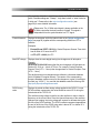
General pane
Device status
Displays the status of the internal clock.
Possible states are: Initializing, locking, locked, unlocked, hold-over and
hardware error.
See the Output status page (see page 43) for more information.
PTP
Displays the current PTP status of the TICRO 100.
Possible states are: Slave, listening, uncalibrated, faulty and disabled.
See the PTP status page (see page 46) or the PTP configuration page
(see page 64) for more information.
UTC date/time
Displays the UTC date and time of the internal clock. The local time can be
derived from the UTC time (Universal Time Coordinated) by adding or
subtracting hours according to the specific time zone. For example, UTC plus
one hour delivers the Central European Time CET (plus two hours during
daylight saving time).
...
40
The TICRO 100 Web Interface
See the Output status page (see page 43) or the Output configuration
page (see page 58) for more information.
Product name
Displays the exact product name.
Serial number
Displays the serial number of the TICRO 100.
Software version
Displays the software version currently installed on the TICRO 100.
Kernel version
Displays the kernel version used in the currently installed operating software.
Hardware revision
Displays the hardware version of the TICRO 100.
Uptime
Displays the time the TICRO 100 is in operation since the last power-up or
reset.
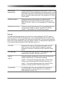
Network pane
IPv4 address
Displays the currently assigned IPv4 address of the TICRO 100.
If configured dynamically, the IP address is assigned automatically by an IPv4
DHCP server (if available in the network) or the TICRO 100 itself. The IPv4
address can also be set manually by the user.
IPv6 address
Displays the currently assigned IPv6 address of the TICRO 100.
If configured dynamically and a IPv6 router is available in the network, the IP
address is assigned automatically. The IPv6 address can also be set manually
by the user.
MAC address
Displays the unique MAC address (Media Access Control Address) of the
TICRO 100.
Host name
Displays the host name of the TICRO 100. The host name is set to the serial
number by default but can be changed by the user. The serial number is
available on the type plate on the bottom side of the TICRO 100.
Domain name
Displays the domain name set by the user (e.g.: omicron.at).
Refer to the Network status page (see page 53) or the Network configuration page (see
page 68) for more information about the network settings.
41
TICRO 100 User Manual
8.2
Status Section
The status information is presented in four pages:
•
Output (see page 43)
•
PTP (see page 46)
•
Network (see page 53)
•
Log Viewer (see page 56)
Some elements provide an edit hyperlink. Click this hyperlink to directly open the
corresponding configuration page (see page 57) .
42
The TICRO 100 Web Interface
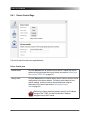
8.2.1
Output Status Page
The Output status page displays the configurations and states of the outputs and information about
the settings and the status of the internal clock.
Output tabs Overview, 1 (BNC), 2 (BNC), 3 (OC), 4 (Fiber) and 5 (Fiber)
The Overview tab displays an overview of the states and the configured time signals (IRIG-B, PPX,
DCF77, etc.) for all available outputs. An LED indicates whether the output is active or not:
Green LED: Output active
Gray LED, text displayed in orange: Output muted
Gray LED, text displayed in black: Output disabled
The tabs for the individual outputs are named by the output number and the interface or socket
type, for example 2 (BNC) for BNC output 2, or 4 (Fiber) for fiber-optic output 4. The information
displayed in these tabs depends on the signal mode configured for the specific output (IRIG-B, PPX,
DCF77, etc.). Please refer to section Output Configuration Page on page 58 for detailed information
about the parameters and settings available for the individual output signal modes.
43
TICRO 100 User Manual
Clock information pane
Device status
Displays the device status of the TICRO 100. The following device states are
possible:
Initializing: The boot process of the TICRO 100 is in progress after providing
supply voltage to the device or after a device reboot. When the boot process is
finished, the TICRO 100 changes to the locking state.
Locking: The TICRO 100 tries to lock to the PTP time signal. If it is able to
reach its defined accuracy within a maximum of 5 minutes, the TICRO 100
changes to the locked state. If not, it changes to the unlocked state.
Locked: The TICRO 100 receives PTP time information from a PTP
grandmaster clock and is locked to this signal. It is able to provide its defined
accuracy. The typical overall accuracy of better than 200 ns is reached after
approximately 15 minutes of operation in the locked state. Please note that the
absolute overall system accuracy depends on the accuracy of the PTP
grandmaster clock and the PTP compliance of the network infrastructure.
Hold over: If the TICRO 100 was in the locked state before, it enters the holdover state when it loses synchronization to the PTP time signal. If configured in
the output configuration (see page 58) , the TICRO 100 continues to output
time signals during the hold-over state. However, synchronization of these
output signals is then performed using the internal oscillator (OCXO) instead of
the PTP time signal. The maximum duration for the hold-over state is 24 hours.
If the TICRO 100 was less than 48 hours in the locked state before, the
maximum duration for the hold-over state is half the "locked" time.
Unlocked: The TICRO 100 could not synchronize to a PTP time signal and
reach its defined accuracy within 5 minutes after powering-up (or a device
reboot) or the hold-over state elapsed when the TICRO 100 was in the locked
stated before and lost synchronization.
Hardware error: The device-internal hardware check failed. Reboot the
TICRO 100 (see Device Control page on page 80). If the hardware error
status still persists after the reboot, send the TICRO 100 to OMICRON Lab for
repair (for contact information, please refer to section Support on page 100).
Outputs active
The TICRO 100 can be configured to automatically deactivate its outputs if it is
not able to provide time signals with sufficient accuracy. The behavior of this
automatic deactivation is defined in the Output configuration page (see
page 58) .
...
44
The TICRO 100 Web Interface
This parameter indicates in which device states the TICRO 100 outputs are
active. Possible settings are: "Always", "only when locked" or "when locked or
in hold-over". Please refer to the output configuration section (see
page 58) for more detailed information.
Please note: The 10 MHz output signal is always available on the
10 MHz output after the boot process is finished. This signal is
independent from the synchronization to a PTP signal.
Current timezone
Displays the timezone set for the internal clock in the Output configuration
page (see page 58) together with the corresponding offset from UTC in
brackets.
Examples:
Next DST change
•
Europe/Vienna (CEST +02:00) for Central European Summer Time which
has an offset of +2 hours from UTC
•
or UTC (UTC + 00:00) for UTC
Displays when the next daylight saving time changeover will take place.
Example:
2014-10-26T01:00+00:00 means that the next changeover will take place on
October 26, 2014 on 1 o'clock UTC time. For example, Central European
Summer Time (UTC + 2 hours) then changes back to Central European Time
(UTC + 1 hour).
The daylight saving time changeovers are defined in a timezone database
which is updated in irregular intervals. The version of the corresponding
timezone database used as source for this changeover is given in brackets in
this field (e.g. V2014.7). You can find this database under the following URL:
http://pecl.php.net/package/timezonedb
OCXO tuning
value
Displays the actual oscillator tuning voltage applied to the OCXO. For new
OCXO oscillator components, this value should be around 50 % during the
locked state of the TICRO 100.
The oscillator tuning voltage is used to tune the oscillator in order to hold its
frequency on the correct value. Since the inherent frequency of the oscillator
changes due to aging, the tuning voltage will increase or decrease during the
life time of the OCXO oscillator. The OCXO oscillator component approaches
the end of its life time if the OCXO tunig value is above 90 % or below 10 %
during the locked state of the TICRO 100.
45
TICRO 100 User Manual
8.2.2
PTP Status Page
The following information is displayed in the PTP status page.
Port pane
The Port pane displays information on the current state and configuration of the PTP port of the
TICRO 100.
Port state
Displays the current PTP state of the network port of the TICRO 100.
Listening: After initialization, the TICRO 100 is listening for messages
from a PTP grandmaster clock (e.g., an OTMC 100) in the network.
The purpose of this state is to allow orderly addition of a clock to a
domain in the network. If so, the TICRO 100 enters the uncalibrated
state.
Uncalibrated: This is a transient state to allow synchronization to a
PTP time signal. After synchronization, the TICRO 100 enters the slave
state.
Slave: The TICRO 100 receives PTP time information from a
grandmaster with sufficient accuracy via the network port. It is
synchronized to a PTP signal (normal operating state).
...
46
The TICRO 100 Web Interface
Faulty: The TICRO 100 detected a fault condition. Further details
about the error can be found in the log file. Synchronization to a PTP
time signal is not possible.
Disabled: The PTP service has been disabled in the network
configuration (see page 68) of the TICRO 100 or via the Application
Programming Interface API. The TICRO 100 cannot synchronize to a
PTP time signal.
See IEEE 1588-2008, clause 9.2.5 for more detailed information.
Delay mechanism
Displays which PTP delay mechanism is currently used by the
TICRO 100. The value of this parameter may either be E2E (end-toend) or P2P (peer-to-peer). The PTP delay mechanism used depends
on the PTP profile selected in the PTP configuration (see page 64) .
Sync interval [s]
Displays the mean synchronization interval for multicast messages
(interval between successive Sync messages).
This parameter is set in the PTP configuration (see page 64) .
Sync Interval = 2Log sync interval seconds, see IEEE 1588-2008, clause
8.2.5.4.3.
Announce interval [s]
Displays the mean time interval between successive Announce
messages. See IEEE 1588-2008, clause 8.2.5.4.1.
This parameter is set in the PTP configuration (see page 64) .
Announce interval = 2Log announce interval seconds.
Announce receipt timeout
Displays the number of "Announce Interval" intervals that have to pass
without the receipt of an Announce message before an
ANNOUNCE_RECEIPT_TIMEOUT_EXPIRES event occurs. See
IEEE 1588-2008, clause 8.2.5.4.2.
This parameter is set in the PTP configuration (see page 64) .
Minimum pdelay request
interval [s]
Displays the minimum permitted mean time interval between
successive Pdelay_Req messages. See "logMinPdelayReqInterval" in
IEEE 1588-2008. Only available for PTP profiles Default P2P and
Power systems.
This parameter is set in the PTP configuration (see page 64) .
Minimum pdelay request interval = 2Log min pdelay request interval seconds, see
IEEE 1588-2008, clause 8.2.5.4.5.
47
TICRO 100 User Manual
Minimum delay request
interval [s]
Displays the minimum permitted mean time interval between
successive Delay_Req messages. This value is determined and
advertised by a master clock based on the ability of the master. Only
available for PTP profile Default E2E.
This parameter is set in the PTP configuration (see page 64) .
Minimum delay request interval = 2Log min delay request interval seconds, see
IEEE 1588-2008, clause 8.2.5.3.2.
Peer mean path delay [ns]
Displays the estimate of the current one-way propagation delay on the
link computed using the peer delay mechanism. If the delay
mechanism is E2E, this value is zero. See IEEE 1588-2008, clause
8.2.5.3.3.
Delay asymmetry [ns]
Displays the asymmetry delay. The asymmetry delay is defined to be
positive when the master-to-slave or responder-to-requestor
propagation time is longer than the slave-to-master or requestor-toresponder propagation time. See IEEE 1588-2008, clause 7.4.2.
Time (master -> slave) = meanPathDelay + delayAsymmetry
Time (slave -> master) = meanPathDelay - delayAsymmetry
Profile id
Displays the profile identity. The profile identity identifies the PTP
profile implemented by the port indicated by the
targetPortIdentity.portNumber member of the field.
See IEEE 1588-2008, clause 15.5.3.1.2.10.
Network protocol
Displays the network protocol selected for the Transport parameter in
the PTP configuration (see page 64) .
Possible values are "UDPIPv4" (transport via UDP packets over IPv4),
"UDP IPv6" (transport of the PTP packets via UDP over IPv6), and
IEEE 802.3 (transport via Ethernet packets according to IEEE 802.3).
VLAN ID
Displays the Vlan ID. The Power systems profile according to
IEEE C37.238-2011 requires an IEEE 802.1Q VLAN tag. This value
represents the VID (VLAN Identifier) field (12 bits) within the TCI (Tag
Control Identifier). See IEEE C37.238-2011, clause 5.6. Only available
for PTP profile Power systems.
This parameter is set in the PTP configuration (see page 64) .
48
The TICRO 100 Web Interface
VLAN priority
Displays the Vlan priority. The Power Profile according to
IEEE C37.238-2011 requires an IEEE 802.1Q VLAN tag. This value
represents the PCP (Priority Code Point) field (3 bits) within the TCI
(Tag Control Identifier). See IEEE C37.238-2011, clause 5.6. Only
available for PTP profile Power systems.
This parameter is set in the PTP configuration (see page 64) .
Default pane
The Default pane displays the current configuration/state of the internal clock of the TICRO 100.
Clock identity
Displays the clock identity. IEEE 1588-2008, clause 7.5.2.2, requires that
each clock in a PTP network has a unique clock identifier. This identifier
is an 8-octet array. The TICRO 100 automatically sets the clock identity
to a unique value based on the device's MAC address according to
IEEE 1588-2008, clause 7.5.2.2.2.
Clock class
Displays the current clock class of the TICRO 100 (see IEEE 1588-2008,
clause 7.6.2.4). The clock class is broadcast in the corresponding PTP
data packets. The value of the clock class parameter is automatically set
by the TICRO 100. Currently, the TICRO 100 supports only the Slave
clock class, i.e., it always receives its time information from a
grandmaster.
Domain number
Displays the domain number of the TICRO 100. The domain number
specifies the PTP domain (see IEEE 1588-2008, clause 7.1) in which the
TICRO 100 participates. All clocks in a network that shall be
synchronized to each other must participate in the same PTP domain,
i.e., have the Domain number parameter set to the same value.
This parameter is set in the PTP configuration (see page 64) .
Local time inaccuracy
Displays the maximum time inaccuracy in ns that the device contributes
to the network time inaccuracy. See IEEE C37.238-2011, clause 5.13.
Only available for PTP profile Power systems.
This parameter is set in the PTP configuration (see page 64) .
Network time inaccuracy
Displays the network time inaccuracy in ns to be transmitted in
IEEE C37.238 TLV. See IEEE C37.238-2011, clause 5.13. Only available
for PTP profile Power systems.
This parameter is set in the PTP configuration (see page 64) .
49
TICRO 100 User Manual
Parent pane
The Parent pane displays information about the current grandmaster clock of the network/domain in
which the TICRO 100 operates.
Port identity
Displays the port identity. This parameter states the port identity of the
TICRO 100 as defined by IEEE 1588-2008, clause 7.5.2, in the format
portNumber@clockIdentity.
Grandmaster identity
Displays the grandmaster identity. This is the unique identifier of the
clock that is currently the grandmaster clock of the network or domain
in which the TICRO 100 participates.
Grandmaster clock class
Displays the grandmaster clock class. This parameter specifies the
current clock class of the current grandmaster clock in the network or
domain (see IEEE 1588-2008, clause 7.6.2.4). The value of the
Grandmaster clock class parameter is automatically set by the current
grandmaster clock depending on the source of time that is currently
available.
Grandmaster clock
accuracy
Displays the current accuracy of the internal clock of the current
grandmaster clock with regard to TAI. See IEEE 1588-2008, clause
7.6.2.5 for details.
Grandmaster clock
variance
Displays the grandmaster clock variance. The Grandmaster clock
variance parameter is set to the PTP variance value specified by IEEE
1588-2008, clause 7.6.3. This parameter gives a measure for the
stability of the internal oscillator of the current grandmaster clock and is
used in the Best Master Clock Algorithm (BMCA) of the PTP protocol.
Grandmaster priority 1
Displays the priority 1 and 2 of the current grandmaster clock. If more
than one PTP grandmaster clock is available in the network, a clock
with a lower Priority 1 value will always be the preferred master clock
over a clock with a higher Priority 1 value (see IEEE 1588-2008, clause
6.6.2.3). A value in the range from 0 to 255 may be assigned to the
Priority 1 parameter (see IEEE 1588-2008, clause 7.6.2.2).
Grandmaster priority 2
The Priority 2 parameter (see IEEE 1588-2008, clause 7.6.2.3) is used
if several devices have the same Priority 1 parameter value and the
same clock quality (class, accuracy and variance). The Priority 2
parameter thus allows a finer grained ordering among otherwise
equivalent clocks (see IEEE 1588-2008, clause 6.6.2.3). Lower values
take precedence.
50
The TICRO 100 Web Interface
IEEE C37.238
grandmaster ID
Displays the grandmaster identity announced in IEEE C37.238 TLV. By
sending this ID, the current grandmaster clock identifies itself as a valid
power profile grandmaster. A power profile slave will ignore all masters
that do not provide a setting for this field. Only available for PTP profile
Power systems.
GM time inaccuracy
Displays the maximum time inaccuracy in ns that the current
grandmaster clock contributes to the network time inaccuracy. See
IEEE C37.238-2011, clause 5.13. Only available for PTP profile Power
systems.
Network time inaccuracy
Displays the network time inaccuracy of the current grandmaster clock
in ns announced in IEEE C37.238 TLV. See IEEE C37.238-2011,
clause 5.13. Only available for PTP profile Power systems.
Time pane
The Time pane displays parameters for the time that is currently distributed in the PTP network or
domain in which the TICRO 100 participates (e.g., epoch related parameters like UTC offset or leap
second information), and parameters of the time source currently used. This pane lists the parameter
values of the current grandmaster clock in the network or domain. The data listed here represents the
Time Properties Data set specified in IEEE 1588-2008, clause 8.2.4.
UTC offset
Displays the UTC offset. In PTP systems whose epoch is the PTP
epoch, the value is the offset between TAI and UTC in seconds;
otherwise the value has no meaning. See IEEE 1588-2008, clause
8.2.4.2.
UTC offset valid
True indicates that the value of the UTC offset parameter is valid.
Otherwise false. See IEEE 1588-2008, clause 8.2.4.3.
Leap 59
Displays the boolean values that are used to notify the clocks in the
network or domain that a UTC leap second is pending.
Leap 61
Leap 59 = True means that the last minute of the current UTC day
contains only 59 seconds (see IEEE 1588-2008, clause 8.2.4.4).
Leap 61 = True means that the last minute of the current UTC day
contains 61 seconds (see IEEE 1588-2008, clause 8.2.4.5).
Time traceable
True indicates that the time currently distributed in the network or
domain is traceable to a primary reference, e.g., to GPS (see
IEEE 1588-2008, clause 8.2.4.6)
51
TICRO 100 User Manual
Frequency traceable
True indicates that the frequency determining the timescale currently
distributed in the network or domain is traceable to a primary reference,
e.g., to GPS (see IEEE 1588-2008, clause 8.2.4.7).
PTP time scale
True indicates that the timescale distributed in the network or domain is
the PTP timescale, i.e., TAI time. False if an arbitrary timescale is used.
See IEEE 1588-2008, clause 8.2.4.8.
Time source
Displays the source of time that is used by the current PTP
grandmaster clock (see IEEE 1588-2008, clause 8.2.4.9). Possible
values for this parameter are listed in IEEE 1588-2008, clause 7.6.2.6.
Example: GPS (0x20) means that the current PTP grandmaster clock is
synchronized to a satellite system like GPS.
52
The TICRO 100 Web Interface
8.2.3
Network Status Page
The following information is displayed in the Network status page.
General pane
The General pane displays the general network configuration settings of the TICRO 100.
Hostname
Displays the host name of the TICRO 100. The host name is set to the serial
number by default but can be changed by the user in the network configuration
(see page 68) . The serial number is available on the type plate on the bottom
side of the TICRO 100 (labeled "SerNo").
Domain name
Displays the domain name set by the user in the network configuration (see
page 68) (e.g.: omicron.at).
MAC address
Displays the unique MAC address (Media Access Control Address) of the
TICRO 100.
Network port
Displays the network port (RJ45 or Fiber) currently selected by the automatic
detection function of the TICRO 100 or set by the user in the network
configuration (see page 68) .
53
TICRO 100 User Manual
IPv4 pane
The IPv4 pane displays the IPv4 specific configuration settings of the TICRO 100. The IPv4
configuration is set in the network configuration (see page 68) .
Configuration
Displays the configuration method selected for IPv4.
IPv4 disabled: IPv4 is switched off.
IPv4 static IP address: The IP address was assigned manually by the user.
IPv4 DHCP on: The IP address was assigned automatically by a DHCP server.
IP address
Displays the currently assigned IPv4 address of the TICRO 100
(e.g.: 192.168.1.100).
Network mask
Displays the network mask in dot-decimal notation (e.g.: 255.255.255.0).
Gateway
If set, this parameter displays the gateway address in dot-decimal notation
(e.g.: 192.168.1.1).
Nameserver 1
Nameserver 2
If set, these parameters display the address of the first and second name
server selected in dot-decimal notation (e.g.: 192.168.1.50).
IPv6 pane
The IPv6 pane displays the IPv6 specific configuration settings of the TICRO 100. The IPv6
configuration is set in the network configuration (see page 68) .
Configuration
Displays the configuration method selected for IPv6.
IPv6 disabled: IPv6 is switched off.
IPv6 static IP address: The IP address was assigned manually by the user.
IPv6 auto configuration: The IP address was assigned automatically using
the Stateless Address Autoconfiguration (SLAAC).
IPv6 auto configuration (manual DNS): The IP address was assigned
automatically using the Stateless Address Autoconfiguration (SLAAC) but the
user manually specified possible DNS servers in the network configuration (see
page 68) .
IP address
Displays the currently assigned IPv6 address of the TICRO 100.
Network mask
Displays the network mask in dot-decimal notation.
Gateway
If set, this parameter displays the gateway address in hexadecimal notation.
Nameserver 1
Nameserver 2
If set, these parameters display the address of the first and second name
server in hexadecimal notation.
54
The TICRO 100 Web Interface
Link local address
Link local mask
Displays the link local address and the respective mask automatically assigned
by the Stateless Address Autoconfiguration (SLAAC) if the IPv6 auto
configuration option is selected for IPv6 in the network configuration (see
page 68) .
55
TICRO 100 User Manual
8.2.4
Log Viewer Page
The Log Viewer page shows all events logged in the internal log file. Which types of events are
actually logged by the system can be selected in the log & notifications configuration (see page 72) .
ERR
Error messages are displayed in red.
WARNING
Warning messages are displayed in orange.
NOTICE
Notice messages are displayed in black.
INFO
All other messages (debug messages, information, etc.) are displayed in gray.
Click Clear View to delete the messages displayed in the Log Viewer window. This does not clear the
log file. Re-opening the Log Viewer will again display all messages logged in the log file.
Click Export Log to export the log file content to a text file (file extension .log).
The log file is cleared with each reboot of the TICRO 100 (see section Performing a Reboot
of the TICRO 100 on page 31 or Performing a Reboot of the TICRO 100 on page 34). If the
maximum size of the log file is reached, the system automatically deletes old log file entries
in order to release memory space for new entries.
56
The TICRO 100 Web Interface
8.3
Configuration Section
Configuration of the TICRO 100 is done in five pages:
•
Output (see page 58)
•
PTP (see page 64)
•
Network (see page 68)
•
Log & Notification (see page 72)
•
Security (see page 75)
57
TICRO 100 User Manual
8.3.1
Output Configuration Page
Select a tab to configure the corresponding output and/or specify the clock settings. Click the Save
button to save and apply your changes to the TICRO 100.
The 10 MHz signal output is always active and cannot be configured.
Output tabs 1 (BNC), 2 (BNC), 3 (OC), 4 (Fiber) and 5 (Fiber)
The configuration tabs for the individual outputs are named with the output number and the interface
or socket type:
1 (BNC) and 2 (BNC): 50 Ω BNC outputs 1 and 2
3 (OC): Optocoupler output 3
4 (Fiber) and 5 (Fiber): Fiber-optic outputs 4 and 5
58
The TICRO 100 Web Interface
The possible output settings are to a wide extent identical for all outputs and types. They are
explained in the following tables.
Time base
Select the time base used for the generation of the time signal of the
corresponding output: TAI (International Atomic Time), UTC (Universal Time
Coordinated) or Local time (time selected in the clock settings, for example
CEST + 2:00 hrs).
DCF77 signals are always based on Central European Time or Central
European Summer Time (CET/CEST).
Mode
Select the time code of the output signal. Depending on the selected mode,
further configuration parameters may be available.
Disabled: No signal is applied at the output. The output is always off.
IRIG-B: The output provides an IRIG-B signal. For the BNC outputs 1 and 2
you can furthermore select whether this signal should be modulated or not.
See the following table for the available parameters.
PPX: The output provides a PPX signal. See the following table for the
available parameters.
DCF77: The output provides an unmodulated DCF77 time signal. No other
configuration parameters are available for the DCF77 mode.
Trigger (single pulse): The output provides one pulse at a defined point in
time. See the following table for the available parameters.
Trigger (PPX): The output provides a PPX signal starting at the defined point
in time. See the following table for the available parameters.
Output muting
Use this check box to enable or mute the corresponding output. Muted outputs
are always off.
59
TICRO 100 User Manual
Parameter
name
Modulation
Coded
expressions1
Parameter available for mode
IRIG-B
PPX
Trigger
(PPX)
Description
Trigger
(single
pulse)
x
(BNC
only)
Select whether the output should
deliver a modulated or an
unmodulated IRIG-B time signal.
x
Use the check boxes to specify the
coded expressions the IRIG-B
signal should contain: Control
functions CF, Straight binary
seconds SBS and/or BCDYEAR.
Please refer to the IRIG standard
for more detailed information.
Pulses per
second
x
x
Select the number of pulses the
output signal should contain: 1, 10,
100 or 1000 pulses per second
(PPS), 1 pulse per minute (PPM) or
1 pulse per hour (PPH).
Or select Custom and specify the
pulse interval in seconds.
Pulse width2
x
x
Enter the pulse width in ns for your
PPX signal.
Time
reference2
x
x
Select whether the falling edge or
the rising edge of the output pulse
should be synchronized to the time
base.
Next trigger
1, 2 See the following footnotes for more detailed explanation.
60
x
x
Select the point in time the trigger
signal should occur (or start). Click
the date field and select a date/time
from the calendar dialog or select
Set to next full minute or Set to
next full hour to start the trigger at
the next full minute or hour.
The TICRO 100 Web Interface
Footnote 1
Using coded expressions, the IRIG-B signal can include additional information like control functions,
straight binary seconds and BCDYEAR. The naming of the IRIG-B code changes depending on the
included information. Example: B000 is an IRIG-B signal with control functions and straight binary
seconds activated. Refer to the following IRIG-B coding scheme.
IRIG-B Coding Scheme
CF
SBS
Bxx0
x
x
Bxx1
x
BCDYEAR
Bxx2
Bxx3
x
Bxx4
x
Bxx5
x
x
x
x
Bxx6
Bxx7
x
x
x
CF: Control Functions
SBS: Straight Binary Seconds
Source: IRIG Standard 200-04 (4.1 Time Code Formats)
Detailed information about the IRIG-B coding scheme can be found in the IRIG Standard 200-04
under "Time Code Formats".
Footnote 2
The following figure explains the pulse width and the time reference parameters.
Time reference
rising edge
Pulse width
Time reference
falling edge
Pulse width
UTC time (start of second)
61
TICRO 100 User Manual
Clock settings pane
Outputs active
You can configure the TICRO 100 to automatically deactivate its outputs if it is
not able to provide time signals with sufficient accuracy. Use this parameter to
select the behavior of this automatic deactivation.
Always: Automatic deactivation is switched off. The outputs are always on.
Only when locked: The TICRO 100 deactivates the outputs if the device
status is not locked. In the locked state, the time signals output by the
TICRO 100 are synchronized to the received PTP time signal.
When locked or in hold over: The TICRO 100 deactivates the outputs if the
device is not in the locked or the hold-over state. In the hold-over state, the
time signals output by the TICRO 100 are derived from the internal oscillator.
For information about the device states, please refer to the description of the
Output status page (see page 43) .
Current timezone
Select one of the timezones offered in the list or UTC. The displayed offset
from UTC is used to calculate the local time of the TICRO 100 (for example,
Europe/Vienna (CEST +2:00)).
Or select "Manual" from the list to set the timezone manually. Please refer to
subsection "Setting the timezone manually" below.
Next DST change
Displays when the next daylight saving time changeover will take place.
Example:
2014-10-26T01:00+00:00 means that the next changeover will take place on
October 26, 2014 on 1 o'clock UTC. For example, Central European Summer
Time (UTC + 2 hours) then changes back to Central European Time (UTC +
1 hour).
The daylight saving time changeovers are defined in a timezone database
which is updated in irregular intervals. The version of the corresponding
timezone database used as source for this changeover is given in brackets in
this field (e.g. V2014.7). You can find this database under the following URL:
http://pecl.php.net/package/timezonedb
Click set manually to set the next daylight saving time changeover manually.
Please refer to subsection "Setting the timezone manually" below.
Setting the timezone manually
Selecting "Manual" from the Current timezone list or clicking the set manually link behind Next DST
timezone displays additional fields for adjusting the timezone manually.
62
The TICRO 100 Web Interface
1. Enter the desired offset of your local time from UTC before the daylight saving time changeover
and after the daylight saving time changeover to the corresponding fields. Use the requested
format hh:mm.
2. Click the Next DST change field to open a calendar dialog allowing for the selection of the date
and time for the daylight saving time changeover. In this dialog, set the date and time or click Now
to set it to the current date and time of your computer. Click Done to close the calendar and to
apply your settings to the Next DST change field.
A warning sign is displayed if the selected time for the next daylight saving time
changeover is in the past.
3. Click the Save button to save and apply your settings to the TICRO 100.
63
TICRO 100 User Manual
8.3.2
PTP Configuration Page
Select the corresponding tab to specify your PTP configuration settings. Click the Save button to save
and apply your PTP configuration changes to the TICRO 100.
General tab
PTP profile
Use this list box to select the PTP profile. The Default E2E and Default
P2P profiles are intended for application in industrial environments that
use the IEEE 1588-2008 Precision Time Protocol.
Default E2E: The default profile with the end-to-end mechanism as
defined in IEEE 1588-2008 is used.
Default P2P: The default profile with the peer-to-peer mechanism is used.
Power systems: The Power Profile acc. to IEEE C37.238-2011 is used.
This PTP profile is intended for application in power system environments
that use the Precision Time Protocol according to the IEEE Std.
C37.238-2011 (IEEE Standard Profile for Use of IEEE 1588-2008
Precision Time Protocol in Power System Applications).
User description
Enter a description for the TICRO 100. This may be required to identify the
TICRO 100 uniquely if you are using more than one TICRO 100 device in
the network.
Max. GM inaccuracy
Select the maximum acceptable inaccuracy of the PTP time distributed in
the network. If the inaccuracy of the PTP grandmaster clock is greater
than this value, the TICRO 100 will no longer synchronize its output
signals to the PTP grandmaster clock. The TICRO 100 will change to the
hold-over state and derive its output signals from its internal oscillator
instead (see also the hold-over device state in the Output Status Page
section (see page 43) ).
64
The TICRO 100 Web Interface
Default tab
Domain number
The domain number specifies the PTP domain (see IEEE 1588-2008,
clause 7.1) in which the TICRO 100 participates. All clocks in a network
that shall be synchronized to each other must participate in the same PTP
domain, i.e., have the Domain number parameter set to the same value.
Engineered network
time inaccuracy
This value is set at the end device to represent the worst network time
inaccuracy from this device to all preferred grandmasters. See
"EngTimeInacc" in IEEE C37.238-2011. Only available for PTP profile
Power systems.
Local time inaccuracy
This value shall be a more precise value of the clockAccuracy of the
clockQuality field specified in clause 7.6.2.5 and Table 6 of the
IEEE 1588-2008 standard. Only available for PTP profile Power systems.
Port tab
Transport
Select the transport mechanism (network protocol) from the list. The
protocols available in the list depend on the PTP profile selected:
UDP IPv4: User Datagram Protocol (UDP) for Internet Protocol (IP)
version 4. Only available for PTP profiles Default E2E and Default P2P.
UDP IPv6: User Datagram Protocol (UDP) for Internet Protocol (IP)
version 6. Only available for PTP profiles Default E2E and Default P2P.
IEEE 802.3: Ethernet protocol according to IEEE 802.3.
VLAN ID
The Power Profile according to IEEE C37.238-2011 requires an IEEE
802.1Q VLAN tag. This value represents the VID (VLAN Identifier) field (12
bits) within the TCI (Tag Control Identifier). See "VlanId" in
IEEE C37.238-2011. Only available for PTP profile Power systems.
VLAN PCP
The Power Profile according to IEEE C37.238-2011 requires an IEEE
802.1Q VLAN tag. This value represents the PCP (Priority Code Point)
field (3 bits) within the TCI (Tag Control Identifier). Only available for PTP
profile Power systems.
Log sync interval
Use this field to specify the logarithm to the base 2 of the mean
synchronization interval (interval between successive Sync messages in 2x
seconds) for multicast messages. See "logSyncInterval" in
IEEE 1588-2008.
...
65
TICRO 100 User Manual
For example, a value of 2 will result in a synchronization interval of 4
seconds (= 22).
Note:
Sync interval = 2Log sync interval seconds, see IEEE 1588-2008, clause
8.2.5.4.3.
Log min pdelay request Use this field to specify the logarithm to the base 2 of the minimum
interval
permitted mean time interval between successive Pdelay_Req messages
(interval in 2x seconds). See "logMinPdelayReqInterval" in
IEEE 1588-2008. Only available for PTP profiles Default P2P and Power
systems.
For example, a value of 0 will result in an interval of 1 second (= 20).
Note:
Minimum pdelay request interval = 2Log min pdelay request interval seconds, see
IEEE 1588-2008, clause 8.2.5.4.5.
Log min delay request
interval
The logarithm to the base 2 of the minimum permitted mean time interval
between successive Delay_Req messages (interval in 2x seconds). This
value is determined and advertised by a master clock based on the ability
of the master. Only available for PTP profiles Default E2E.
For example, a value of 1 will result in an interval of 2 seconds (= 21).
Range:
Log sync interval <= Log minimum delay request interval <=
Log sync interval + 5
Note:
Minimum delay request interval = 2Log min delay request interval seconds, see
IEEE 1588-2008, clause 8.2.5.3.2.
See IEEE 1588-2008 for more detailed information.
Log announce interval
Use this field to specify the mean time interval in 2x seconds between
successive Announce messages. See "logAnnounceInterval" in
IEEE 1588-2008.
For example, a value of 1 will result in an interval of 2 seconds (= 21).
Announce receipt
timeout
66
Use this field to specify the number of "Log Announce Interval" intervals
that have to pass without the receipt of an Announce message before an
ANNOUNCE_RECEIPT_TIMEOUT_EXPIRES event occurs. See
"announceReceiptTimeout" in in IEEE 1588-2008.
The TICRO 100 Web Interface
IPv6 multicast scope
Only available if "Transport" is set to "UDP IPv6".
For UDP IPv6 transport, select the multicast scope that shall be used for
all PTP messages except peer delay mechanism messages. For more
detailed information, see IEEE 1588-2008, clause E.3, and IETF RFC
4921 (2006), section 2.7.
For peer delay mechanism messages the IPv6 multicast address FF02::6B
is used. For all other messages the IPv6 multicast address FF0X::181 is
used, where the value of X is selected by the IPv6 multicast scope setting.
All clocks in a network that shall be synchronized via PTP over
UDP IPv6 must use the same multicast scope setting. In earlier
versions of the TICRO 100 or OTMC 100 firmware this setting is
not available. The multicast scope is permanently set to
"0x5: Site-Local scope" on these devices. Configure your
TICRO 100 to "0x5: Site-Local scope" to allow synchronization to
such devices or update older devices with a new firmware image
(see section Running a Software Update for the
TICRO 100 on page 31).
67
TICRO 100 User Manual
8.3.3
Network Configuration Page
The network configuration parameters and settings are organized in different panes and tabs. They
are explained in the subsections below.
Click the Save button to save and apply your network configuration changes to the TICRO 100.
General pane
Hostname
Host name (device name) of the TICRO 100. The host name is set to the serial
number by default but can be changed by the user.
Domain name
If a DHCP server is available in the network, the TICRO 100 receives the domain
name from the DHCP server. The domain name can also be set manually by the
user (e.g.: omicron.at).
68
The TICRO 100 Web Interface
Network
interface
Select the network port the TICRO 100 should use for communication and
reception of the PTP protocol. The TICRO 100 can use only one Ethernet port
(RJ45 or fiber-optic port) at a time.
Auto select: The TICRO 100 automatically detects on which port an operative
Ethernet network is connected and selects this port for communication. The
TICRO 100 selects the RJ45 port if no operative Ethernet network is detected on
any port. This is the default setting of the TICRO 100 after the first power-up or
after a factory reset.
100BASE-TX (RJ45): The TICRO 100 uses the RJ45 Ethernet port for
communication, even if an operative Ethernet network is connected to its fiberoptic network port.
100BASE-FX (FIBER): The TICRO 100 uses the fiber-optic Ethernet port for
communication, even if an operative Ethernet network is connected to its RJ45
network port.
It is strongly recommended to select the network port after powering up
the TICRO 100 and accessing the TICRO 100 Web Interface the first
time. Otherwise the TICRO 100 could possibly select the wrong port if,
for example in case of a voltage outage, the TICRO 100 comes up
before the network is available.
If you selected a specific network port (RJ45 or fiber-optic) and applied
this setting to the TICRO 100, it is no longer possible to access the
TICRO 100 Web Interface via the other network port. To change this
port selection, you must then access the TICRO 100 Web Interface via
the USB port or perform a factory reset using the reset button on the
device (see section Performing a Factory Reset (Reset to Factory
Defaults) on page 34) to reset the network interface configuration to the
default settings.
IPv4 tab
Click this tab to configure the IPv4 settings according to your needs:
IPv4 disabled
IPv4 is switched off.
IPv4 static IP
address
Select static to set the IP address manually. The page then displays fields for
entering the IP address, the Network mask, the Gateway address and the
Name server address in dot-decimal notation (e.g.: 192.168.1.100).
69
TICRO 100 User Manual
IPv4 DHCP on
The IP address is assigned automatically by a IPv4 DHCP server (if available in
the network) or the TICRO 100 itself. The IP address assigned is displayed in the
Network status page (see page 53) and the Overview page (see page 39) .
IPv6 tab
Click this tab to configure the IPv6 settings according to your needs:
IPv6 disabled
IPv6 is switched off.
IPv6 static IP
address
Select static to set the IP address manually. The page then displays fields for
entering the IP address, the Gateway address and the Name server address in
hexadecimal notation (e.g.: 2607:f0d0:2001:a::10), and the Network mask in
decimal notation.
IPv6 auto
configuration
The IP address is assigned automatically using the Stateless Address
Autoconfiguration (SLAAC). The IP address assigned is displayed in the
Network status page (see page 53) and the Overview page (see page 39) .
Additionally, the user has the option to manually specify DNS servers by
selecting the IPv6 auto configuration (manual DNS) option and entering DNS
server addresses to the Name server fields (in hexadecimal notation, e.g.:
2607:f0d0:2001:a::10).
IPv6 auto
configuration
(manual DNS)
Services pane
Use the check boxes in this pane to enable or disable individual services and processes running on
the TICRO 100 system.
All services are enabled (selected) by default. Disabling services that are not used or
required for your specific application will enhance the device security.
Precision Time Protocol
(PTP)
Select the check box to enable PTP support (reception of time
information via PTP in the network).
Omicron OMFIND
Select the check box to enable the Omicron OMFIND service. This
service is used by the OMICRON Device Browser to automatically
detect OMICRON devices in the network.
70
The TICRO 100 Web Interface
Zeroconf
Select the check box to enable detection of TICRO 100 devices in
the network by clients that are able to handle mDNS/DNS-SD (e.g.,
the Apple Bonjour tool, as an alternative to the OMFIND service
used by the OMICRON Device Browser).
File Transfer Protocol (FTP)
Select the check box to enable access via FTP. The TICRO 100 is
able to provide FTP server functionality, which can be used for
example to transfer a configuration file to the TICRO 100.
Trivial File Transfer Protocol
(TFTP)
Select the check box to enable access via TFTP. The TICRO 100 is
able to provide TFTP server functionality, which can be used for
example to download a configuration file from the TICRO 100.
71
TICRO 100 User Manual
8.3.4
Log & Notification Configuration Page
The log and notification configuration parameters and settings are explained in the subsections below.
Click the Save button to save and apply your changes to the TICRO 100.
Log pane
Level
Use this list box to select the level as of which you want to have system
messages logged to the selected target. Lower levels include the
messages of higher levels.
The following levels are available (starting from the lowest level): Debug,
Info, Warning, Error, Critical.
72
The TICRO 100 Web Interface
Target
Use this list box to select the target where you want to have the system
messages logged to:
Local logfile only: Logging is performed to the internal log file that can be
viewed using the Log Viewer page (see page 56) in the Status section.
IPv4 syslog server and IPv6 syslog server: Logging is performed to the
internal log file and to the specified syslog server for IPv4 or IPv6 installed
in the network.
Remote host &
Remote port
Use these fields to specify the host name and port number of the syslog
server in the network used as log target for the system messages.
Only active if the Target list box is set to IPv4/IPv6 syslog server.
Remote transport
Use this field to specify the network transport protocol of the IPv4 or IPv6
syslog server, if selected in the Target field.
Select UDP (User Datagram Protocol) or TCP (Transmission Control
Protocol).
Enabled sources
Select the corresponding check box to enable logging for a particular
message type (Kernel messages, PTP messages and/or clock state
messages).
Notifications pane
The event notification function can be used to generate e-mail messages on the occurrence of specific
events.
Enable notifications
Select the check box to enable the event notification function and activate
the fields and controls in this tab.
SMTP host &
SMTP port
Use these fields to specify the host name and port number of the SMTP
(e-mail) server.
Sender e-mail
Use this field to specify the e-mail address of the TICRO 100.
Recipient e-mail
Use this field to specify the recipient e-mail address for the event
notification messages.
PTP notifications
Select the corresponding check box to enable e-mail notification for a
specific event or select Select all to select all check boxes.
Clock notifications
...
73
TICRO 100 User Manual
PTP notifications: Listening, Uncalibrated, Slave, Faulty and Disabled.
Send e-mail notification if the PTP state changed to the corresponding
state. For more information about the clock states, please refer to the PTP
status page (see page 46) .
Clock notifications:
74
•
Locked, Unlocked, Hold-over, Init: Send an e-mail notification if the
clock state changed to the corresponding state. For more information
about the clock states, please refer to the Output status page (see
page 43) .
•
DST change: Send an e-mail notification with every daylight saving
time changeover.
The TICRO 100 Web Interface
8.3.5
Security Configuration Page
The security configuration settings are organized in several tabs. They are explained in the
subsections below.
Click the Save button to save and apply your changes to the TICRO 100.
Access Control tab
Use this tab to define password protection for accessing the TICRO 100.
Change password
Enter your password for accessing the TICRO 100. The TICRO 100 uses the
same password for all services and processes running on the TICRO 100
(e.g., detection by OMICRON OMFIND service, FTP access, etc.)
The password is case sensitive and must have at least 5 characters (letters,
figures or special characters).
Confirm password
Repeat your password for confirmation.
75
TICRO 100 User Manual
Access
Select Password if you want to protect the TICRO 100 against unauthorized
access by specifying a password. Select Anonymous if you do not want to
use password protection.
If password protection is enabled, a login dialog appears when accessing the
TICRO 100 Web Interface.
If you set the Access field to Password without defining a
password, the default password timeterminal will be used.
Protocol
Select HTTP and HTTPs if you want to allow access to the TICRO 100 Web
Interface via the HTTP protocol or the secure HTTPs protocol. Select HTTPs
only if you want to allow access via the secure HTTPs protocol only.
Services
Select Web only to allow access via the Web Interface only or SOAP only if
you want to allow access via the Application Programming Interface API only
(see section Application Programming Interface (API) on page 84 for more
information). Or select Web and SOAP to allow access via both interfaces.
Perform a factory reset on the device if you forgot your password (see Operating Procedures
Performed Directly on the Device on page 34). This will reset and deactivate password
protection for the TICRO 100.
Protocol Restrictions tab
Use this tab to increase the security if you are using the TICRO 100 in a network with high security
demands. Deselecting services that are not required or used for operation makes the TICRO 100
safer against any kind of attacks, for example performed to change the configuration. Deselecting all
options will minimize potential points of attack and thus provide highest security.
Click the corresponding check box to select or deselect an option. All options are selected by default.
Click the Save button to save and apply your protocol restrictions settings to the TICRO 100.
Allow OMFIND
network
configuration
76
The OMFIND service is used by the OMICRON Device Browser to
automatically detect OMICRON devices in the network. However, the Device
Browser also allows for changing the IP address of OMICRON devices
available in the network. Deselect this option to prohibit IP address changes
via the OMICRON Device Browser. If selected, changing the IP address via
the Device Browser is possible.
The TICRO 100 Web Interface
Allow SSH
password login
If this option is enabled, the user can log in to the TICRO 100 via SSH using
the standard user/password authentication (i.e., using the user name and
password defined for the TICRO 100) or using a public/private key pair
previously generated by the user and copied to the TICRO 100.
Deselect this option to prohibit standard user/password authenticated access
to the TICRO 100 via secure shell (SSH). When deselected, access via SSH
is only possible via key based authentication. Deselecting this option reduces
the risk of unauthorized access to the TICRO 100 through brute force attacks.
There are numerous instructions for generating SSH key pairs
available on the Internet.
Generate Certificate tab
When accessing the TICRO 100 via HTTPS, an "untrusted connection" message will appear because
the TICRO 100 does not have a valid certificate.
To avoid such messages, it is necessary to provide the TICRO 100 with such a certificate. There are
two possible ways: Generating a certificate signed by an accredited certification authority or
generating a certificate signed by yourself.
Web browsers usually contain the digital signatures of all accredited certification authorities by default
and will therefore accept certificates signed by those authorities. However, when using a self-signed
certificate, the web browser will not recognize you as a valid certification authority (since it does not
know the signature of "your" certification authority) and thus not accept such certificates. This behavior
can only be eliminated by providing each web browser used to access the TICRO 100 with the digital
signature of "your" certification authority. Due to this, generating a self-signed certificate will in most
cases not be a feasible solution in practice. We recommend to generate a certificate signed by an
accredited certification authority or to accept the "untrusted connection" message displayed when
accessing the TICRO 100.
Proceed as follows to generate a certificate signed by an accredited certification authority:
1. Enter the required information to the fields Domain name, E-mail address, Country code (e.g.,
AT), State, Locality, Organization name and Organizational unit.
2. Click the Download button next to Generate certificate signing request to generate a certificate
and download it from the TICRO 100.
3. Send the certificate to an accredited certification authority.
4. Upload the signed certificate received from the certification authority to the TICRO 100 using the
Upload Certificate tab (see below).
77
TICRO 100 User Manual
5. The web browser will then recognize that the certificate has been signed by an accredited
certification authority and therefore no longer display the "untrusted connection" message when
accessing the TICRO 100.
Proceed as follows to generate a self-signed certificate:
1. Enter the required information to the fields Domain name, E-mail address, Country code (e.g.,
AT), State, Locality, Organization name and Organizational unit.
2. Click the Generate button next to Generate self-signed certificate to generate a certificate on the
TICRO 100 that is signed by yourself.
3. Select HTTPs only for the Protocol option in the Access Control tab and click the Save button.
4. The TICRO 100 automatically performs a restart of the web server.
5. The web browser then displays an "untrusted connection" message. Add the certificate previously
generated for the TICRO 100 to your web browser.
The approach to add the certificate to the web browser strongly depends on the browser
used to access the TICRO 100. Please consult the help system of your web browser for a
detailed description how to handle certificates with your browser.
Upload Certificate tab
Click the Browse... button to navigate to the signed certificate (see above). The path and file name is
displayed in the Certificate field after selecting it in the file open dialog. Then click the Upload button
to upload the certificate to the TICRO 100.
78
The TICRO 100 Web Interface
8.4
Tools Section
The following pages are available in the Tools section:
•
Device Control (see page 80)
•
Software Update (see page 82)
•
Configuration Management (see page 83)
79
TICRO 100 User Manual
8.4.1
Device Control Page
The device control functions are explained below.
Device Control pane
Reboot device
Click the Reboot button to initiate a device reboot. A reboot can also be
performed using the pushbutton on the device (see section Performing a
reboot of the TICRO 100 on page 34).
Factory reset
Click the Reset button to initiate a factory reset in order to reset the device
configuration to the factory defaults. The factory reset deletes all user
specific settings. A factory reset can also be performed using the
pushbutton on the device (see section Performing a factory
reset on page 34).
Performing a factory reset may possibly result in an IP address
change of the TICRO 100 due to automatic IP address
assignment by a DHCP server.
80
The TICRO 100 Web Interface
System snapshot
Click the Download button to download a system snapshot containing all
configuration settings and the log file. The system snapshot contains
important information for the technical support in case of problems.
Downloading a system snapshot may take approx. 30 seconds.
SNMP MIB File
A MIB (Management Information Base) file is required for proper
representation of the power profile settings of the TICRO 100 in SNMP
clients. Click the Download button to download the MIB file from the
TICRO 100.
Uptime
Displays the time the TICRO 100 is in operation since the last power-up.
Set time manually pane
Use these fields to set the time of the internal clock manually. Click the Save button to apply your
clock settings to the TICRO 100.
Setting the time manually is only required and possible if the TICRO 100 does not receive time with
sufficient accuracy via PTP. The manual time settings are overwritten by the PTP time information as
soon as the TICRO 100 locks to a PTP time signal.
New time (UTC)
Click this field to open a calendar dialog allowing for the selection of the
current date and time.
In this dialog, set the date and time or click Now to set it to the current
date and time of your computer. Click Done to close the calendar and to
apply your time settings to the New time (UTC) field.
Leap seconds
A leap second is occasionally applied to UTC time in order to keep its time
of day close to the mean solar time. The latest insertion of a leap second
was done in June 2012 to increase the actual offset of TAI to UTC to 35
seconds. Enter this offset to the Leap seconds field.
The insertion of leap seconds is decided by the International
Earth Rotation and Reference Systems Service (IERS) and
performed irregularly in unpredictable spaces of some years. If
necessary, please investigate on the Internet for the actual TAIUTC offset valid at the time of reading. The TAI-UTC offset is
adjusted automatically as soon as the TICRO 100 locks to a PTP
signal. In this case, a previously entered manual setting is
overwritten.
81
TICRO 100 User Manual
8.4.2
Software Update Page
To perform a software update for the TICRO 100, select the software image file and click the Update
button to start the software update.
The update process may take several minutes. Do not disconnect the TICRO 100 from the power
supply or from the Ethernet or USB connection during this process. The TICRO 100 automatically
restarts after the software update is completed.
Current version
Displays the version number of the software currenty installed on the
TICRO 100.
New image file
Click the Browse... button to navigate to the software image file. The path
and file name is displayed in the field after selecting it in the file open
dialog.
Keep settings
If this check box is selected, the user specific configuration settings are
kept during a software update. Deselect the check box to automatically
reset the device configuration to the factory defaults after a software
update.
If the software update process fails due to any reason, the TICRO 100 will enter a recovery
mode on the next power-up. In this mode, the device provides only a rudimentary Web
Interface (similar to the Software Upgrade page) just allowing for the upload of a software
image.
82
The TICRO 100 Web Interface
8.4.3
Configuration Management Page
Upload pane
XML configuration
Use this function to upload a prepared configuration file to the TICRO 100
and apply this configuration on the device.
Click the Browse... button to navigate to the XML configuration file. The
path and file name is displayed in the field after selecting it in the file open
dialog. Click the Save button to upload and save the configuration file to
the TICRO 100.
Download pane
XML configuration
Click the Download button next to XML configuration to download the
current configuration of the TICRO 100 in XML format.
XSD
Click the Download button next to XSD to download the XML Schema
Definition defining the XML structure of the XML configuration file from the
TICRO 100.
83
TICRO 100 User Manual
9
Application Programming Interface (API)
The TICRO 100 can also be controlled and configured via an application programming interface (API).
Via this API all the functions of the device can be controlled, except the following:
•
Update of the internal software
•
Download of the configuration as XML or the schema definition as XSD
•
Upload of a XML configuration file
•
Upload or creation of certificates
To execute these tasks, please use the functions available in the Tools section and the Security page
of the Configuration section in the Web Interface.
This API is accessible via a SOAP interface offered by the webserver of the device. This means every
SOAP compatible system and/or language can be used to create an application to control or configure
the device.
Pre-generated libraries and examples for different languages can be found at
www.omicron-lab.com by visiting the download area in the TICRO 100 section.
This interface can be accessed at [HTTP/HTTPS]://[DeviceIP/Hostname]/Api/Process. The
WSDL file to create a service proxy can be requested at
[HTTP/HTTPS]://[DeviceIP/Hostname]/Api/Wsdl.
Please note that the URLs are case sensitive.
A short example usage is shown below. For a more detailed explanation, please download the
extended API documentation which can be found at the same location as the examples at the link
above or at [HTTP/HTTPS]://[DeviceIP/Hostname]/Help/Api.
//TICRO web server does not support the headers otherwise
System.Net.ServicePointManager.Expect100Continue = false;
var service = new ApiClient();
string status = service.Status(); // or "string status = await service.StatusAsync();"
Debug.WriteLine("Device status: " + status); //prints "Device status: OK"
The "ApiClient" proxy class was generated by the "Add Service Reference…" wizard using Microsoft®
Visual Studio.
84
The OMICRON Device Browser
10
The OMICRON Device Browser
By means of the OMICRON Device Browser you can access network compatible OMICRON devices.
The Device Browser automatically finds all OMICRON and OMICRON Lab devices available in the
computer network.
Having the Device Browser installed on your computer, the OMICRON devices may be displayed in
one of two ways:
1. When using the regular Windows Explorer, the OMICRON devices appear in the Windows
Explorer’s folder tree in a section called OMICRON Devices, their serial numbers presented like
regular first-level folders.
If necessary, right-click on a free area of the Windows Explorer’s folder tree and select the Show
all folders option to display the OMICRON Devices section in the Windows Explorer.
2. Alternatively, double click the OMICRON Devices desktop icon. This launches a Windows Explorer
window listing the OMICRON devices detected in the computer network with their serial number,
device type/name and IP address.
There is no functional difference; use whatever method is more convenient for you. Even though the
Device Browser help system focuses on accessing devices via the "regular" Windows Explorer, when
working from the OMICRON Devices Explorer window, the handling is basically identical.
Click the help button
in the top right corner of the Device Browser Explorer window to view the
Device Browser help providing detailed information about the Device Browser.
85
TICRO 100 User Manual
10.1 Installing the OMICRON Device Browser
The OMICRON Device Browser and its installation program Setup Wizard are included on the
CD ROM accompanying the TICRO 100. Proceed as follows to install the OMICRON Device Browser:
1. Exit all other major programs running on your computer.
2. Insert the CD ROM into your computer’s CD ROM drive and click Install Device Browser on the
start page. Should the start page not be displayed automatically a few seconds after the CD has
been inserted into the CD ROM drive, change to the Windows Explorer and double-click
autorun.exe on the CD ROM.
3. Follow the instructions displayed on the screen to install the software.
Note regarding firewall requirements: The OMFind service sends and receives network
packets on UDP port 4987 and 4988. The OMICRON Device Browser installer will configure
the Windows firewall appropriately during installation on supported systems. If you have a
separate "personal" firewall enabled, ensure that UDP ports 4987 and 4988 are open for the
OMFind service.
10.2 Finding OMICRON Devices in the Device Browser Manually
(OMFind)
Normally the Device Browser automatically finds the OMICRON devices connected to the network. If
not, it is also possible to manually search the network for available OMICRON devices.
1. Right-click the OMICRON Devices desktop icon.
2. On the context menu, select OMFind and then click Find Devices.
3. This will start the Device Discovery tool. This tool is intended to diagnose network/firewall problems
when the Device Browser lists no or not all expected test sets.
4. Click the Start Discovery button to manually search for OMICRON devices connected to the
network. Once the search is finished, the Discovered devices section lists network parameters of
all found OMICRON devices.
Some of the available firewall/tunneling products are capable of stopping even the Start
Discovery feature of the Device Discovery tool. So you will not find any OMICRON devices
on the network this way. In this case, the network parameters list stays empty once a search
is finished. If you experience such a behavior, this may indicate a firewall/tunneling software
blocking the network communication.
Click the help button
in the top right corner of the Device Browser Explorer window to view the
Device Browser help providing detailed information about the OMFind service.
86
The OMICRON Device Browser
10.3 Accessing the TICRO 100 Web Interface
1. Launch the OMICRON Device Browser.
2. The Device Browser will automatically find and display the TICRO 100.
If the IP address configurations of the TICRO 100 and the computer are not compatible, the
respective status is displayed in the Status column. In this case, right-click the TICRO 100 serial
number and select Set Network Configuration to assign a suitable IP address to the TICRO 100.
3. Right-click the TICRO 100 serial number and select Open Web Interface from the context menu.
4. The start page of the TICRO 100 Web Interface is displayed in a web browser.
87
TICRO 100 User Manual
11
Technical Data
You can find more detailed technical data on the OMICRON Lab web site
www.omicron-lab.com.
11.1 Timing Performance
Timing accuracy
PTP time stamping resolution: 8 ns
Hold-over drift in 24 hours after 48 hours of operation (at constant
temperature; the drift depends on the installed oscillator option):
•
Standard oscillator OCXO-100: < 100 µs
(order no.: OL000310, TICRO 100 with OCXO-100)
•
High-precision oscillator OCXO-25: < 25 µs
(order no.: OL000311, TICRO 100 with OCXO-25)
The installed oscillator option is stated on the type plate on the bottom side
of the device.
Supported timing
protocol
PTP according to IEEE 1588-2008 (IEEE 1588 version 2).
PTP (IEEE 1588)
features
Default profiles according to IEEE 1588-2008 Annex J:
•
End-to-end (multicast) and peer-to-peer delay mechanisms
•
PTP over UDP/IPv4, UDP/IPv6 and Ethernet/IEEE 802.3
(IEEE 1588-2008 Annex D, E, and F)
Power profile according to IEEE C37.238-2011 (IEEE Standard Profile for
Use of IEEE 1588 Precision Time Protocol in Power System Applications).
11.2 Power Supply
Possible methods of power supply:
•
Power supply via Power over Ethernet
•
Power supply via the plug-in power supply unit provided on delivery (rear panel DC input socket)
•
Power supply via a suitable external DC supply voltage (front panel DC input socket)
88
Technical Data
The TICRO 100 may be supplied using only one of these power supply options or using a combination
of two or all three methods to provide power supply redundancy (see also chapter Power
Supply on page 21).
If supplied via the rear panel DC power input socket and/or via the front panel DC power input socket,
the TICRO 100 is also able to act as a power sourcing equipment (PSE) for class 1 devices (< 4 W)
according to IEEE 802.3af.
Power over Ethernet
(PoE)
Class 3 powered device (PD) according to IEEE 802.3af.
Front panel DC power
input socket
MC 1.5/2-STF-3.81. Terminal block supplied on delivery. Polarity printed
on the front plate.
Max. power consumption: 13 W
Supply voltage: 18 ... 57 VDC
Max. power consumption: 15 W
Max. conductor cross section: 1.5 mm2.
The used power supply unit must comply with the SELV
standard if product safety according to IEC 61010-1 and
IEC 60255-27 is required.
Rear panel DC power
input socket
Barrel connector for power supply unit supplied on delivery.
Standard DC barrel jack 2.5 x 5.5 x 11 mm, center pin positive.
Supply voltage: 18 ... 57 VDC
Max. power consumption: 15 W
The used power supply unit must comply with the SELV
standard if product safety according to IEC 61010-1 and
IEC 60255-27 is required. The plug-in power supply unit supplied
on delivery complies with the SELV standard.
The DC power input socket on the rear side does not fulfill the
surge requirements of IEC 60255-27. Use the DC power input
socket on the front side if IEC 60255-27 compliance is required.
89
TICRO 100 User Manual
11.3 Frequency Outputs and Time Codes
Electrical specifications
All outputs of the TICRO 100 are electrically connected to the SELV (safety extra low
voltage) insulation group of the device. It is not permitted to connect any voltages that are
not SELV compliant.
10 MHz
50 Ω BNC socket for 10 MHz sine wave signal. Not configurable.
4 dBm ± 2 dB at 50 Ω load.
Short-circuit protected. Ground connected to housing.
Out 1, Out 2
Configurable 50 Ω BNC outputs.
Unmodulated time codes: 2.5 V at 50 Ω load, 5 V at open circuit. TTL
compatible.
Modulated IRIG-B: 3 V amplitude (peak) at 50 Ω load, 6 V amplitude at
open circuit.
Short-circuit protected. Ground connected to housing.
Out 3
Configurable optocoupler output (MSTB 2,5 HC/ 2-STF-5,08 screw
terminal, connector supplied on delivery).
Maximum collector-emitter voltage: 30 V
Maximum current: 100 mA
Supports digital (unmodulated) time codes only.
Out 4, Out 5
Configurable optical ST connector outputs.
820 nm wave length.
Supports digital (unmodulated) time codes only.
90
Technical Data
Supported time codes
IRIG-B
TAI, UTC or local time base.
IRIG-B 00x (unmodulated) or IRIG-B 12x (modulated on 1 kHz carrier).
Coded expressions: control functions, straight binary seconds, BCDyear.
DCF77
Unmodulated. Always CET/CEST.
PPX
TAI, UTC or local time base.
1, 10, 100 or 1000 PPS (pulses per second), 1 PPM (pulse per minute),
1 PPH (pulse per hour) or custom period between 1 pulse per second and
1 pulse per day.
Configurable pulse width (in ns).
Minimum pulse width: 10 ns. Maximum pulse width: 2 s but not larger than
the signal period. Resolution: 1 ns.
Time reference: Falling or rising edge.
Can be combined with Trigger.
Trigger
TAI, UTC or local time base.
1 pulse at a predefined point in time or PPX sequence starting at a defined
point in time. Absolute trigger date and time programmable with 1 s
resolution.
91
TICRO 100 User Manual
11.4 Networking and Management
Management
Configuration and management via Web Interface (HTTP/HTTPS).
TFTP, FTP and SSH access.
Automated configuration via SSH, SOAP and XML files.
Failsafe software upgrade in the field.
Email notifications and syslog functionality (local and remote).
Networking
Twisted-pair (10BaseT/100BaseTX, RJ45) and optical (100BaseFX, LC
multimode) Ethernet connectors. One network interface useable at a time.
IPv4 and IPv6 support.
Power over Ethernet according to IEEE 802.3af.
DHCP.
Zeroconf (MDNS/DNS-SD).
USB
USB 2.0 (type B) connector.
USB network gadget (RNDIS).
Allows network connection to the TICRO 100 and devices connected to
the Ethernet interface of the TICRO 100.
92
Technical Data
11.5 Environmental Conditions
Temperature range
Operation
-20 °C to +50 °C (-4 °F to +122 °F)
Storage
-40 °C to +85 °C (-40 °F to +185 °F)
Degree of protection
IP40 according to IEC 60529.
Climate
Tested according to IEC 60068-2-30, Test Db, damp heat, cyclic (6 cycles,
55°C)
Humidity
5 % ... 95 % relative humidity; no condensation.
Vibration
Tested according to IEC 60068-2-6 and IEC 60255-21-1 (class 1).
Response: frequency range 10 ... 150 Hz; 0.5 g; 1 sweep cycle per axis.
Endurance: frequency range 10 ... 150 Hz; 1 g; 20 sweep cycles per axis.
Shock
Tested according to IEC 60068-2-27 and IEC 60255-21-2 (class 1).
Response: 5 g / 11 ms; half-sinusoid; 3 pulses in each direction; 6
directions.
Withstand: 15 g / 11 ms; half-sinusoid; 3 pulses in each direction; 6
directions.
Bump test: 10 g / 16 ms; half-sinusoid; 1000 pulses in each direction; 6
directions.
11.6 Mechanical Specifications
Dimensions
HxWxD
Dimensions without any connectors plugged in and without DIN rail clip:
54.6 x 171.6 x 121 mm / 2.15 " x 6.75 " x 4.76 "
Weight
< 750 g / < 1.65 lbs
93
TICRO 100 User Manual
11.7 Electromagnetic Compatibility (EMC), Safety, Certificates
Electromagnetic Compatibility (EMC)
General
Radiated emissions according to EN 61326-1, CISPR 11, IEC 60255-25,
EN 55022, class A.
Radiated emissions according to FCC part 15 class A.
Radiated immunity according to EN 61326-1, EN 61000-4-3,
IEC 60255-22-3.
ESD according to EN 61326-1, EN 61000-4-2, IEC 60255-22-2.
Back panel DC power
input socket
Conducted immunity continuous wave according to EN 61326-1,
EN 61000-4-6, IEC 60255-22-6.
EFT (Burst) according to EN 61326-1, EN 61000-4-4, IEC 60255-22-4.
Surge according to EN 61326-1, EN 61000-4-5, IEC 60255-22-5.
ESD according to EN 61326-1, EN 61000-4-2, IEC 60255-22-2.
Front panel DC power
input socket
Conducted immunity continuous wave according to EN 61326-1,
EN 61000-4-6, IEC 60255-22-6.
EFT (Burst) according to EN 61326-1, EN 61000-4-4, IEC 60255-22-4.
Surge according to EN 55024, EN 61000-4-5.
ESD according to EN 61326-1, EN 61000-4-2, IEC 60255-22-2.
RJ45 Ethernet port
Conducted emission according to EN 55022, IEC 60255-25, class A.
Conducted immunity continuous wave according to EN 61326-1,
EN 61000-4-6, IEC 60255-22-6.
EFT (Burst) according to EN 61326-1, EN 61000-4-4, IEC 60255-22-4.
Surge according to EN 61326-1, EN 61000-4-5, IEC 60255-22-5.
ESD according to EN 61326-1, EN 61000-4-2, IEC 60255-22-2.
FIBER Ethernet port
ESD according to EN 61326-1, EN 61000-4-2, IEC 60255-22-2.
10 MHz output, Out 1,
Out 2, Out 3
Conducted immunity continuous wave according to EN 61326-1,
EN 61000-4-6, IEC 60255-22-6.
EFT (Burst) according to EN 61326-1, EN 61000-4-4, IEC 60255-22-4.
ESD according to EN 61326-1, EN 61000-4-2, IEC 60255-22-2.
Out 4, Out 5
94
ESD according to EN 61326-1, EN 61000-4-2, IEC 60255-22-2.
Technical Data
USB port
Conducted immunity continuous wave according to EN 61326-1,
EN 61000-4-6, IEC 60255-22-6.
EFT (Burst) according to EN 61326-1, EN 61000-4-4, EN 55024.
ESD according to EN 61326-1, EN 61000-4-2, IEC 60255-22-2.
Safety Standards
IEC 60950
IEC 61010
IEC 60255
Certificates
Manufactured under an ISO 9001 registered system.
11.8 Compliance Statements
Declaration of Conformity (EU)
The product adheres to the specifications of the guidelines of the council of the European Community
for meeting the requirements of the member states regarding the electromagnetic compatibility (EMC)
Directive 2004/108/EC and the RoHS Directive 2011/65/EU.
FCC Compliance (USA)
This equipment has been tested and found to comply with the limits for a Class A digital device,
pursuant to part 15 of the FCC Rules. These limits are designed to provide reasonable protection
against harmful interference when the equipment is operated in a commercial environment. This
equipment generates, uses, and can radiate radio frequency energy and, if not installed and used in
accordance with the instruction manual, may cause harmful interference to radio communications.
Operation of this equipment in a residential area is likely to cause harmful interference in which case
the user will be required to correct the interference at his own expense.
Changes or modifications not expressly approved by the party responsible for compliance could void
the user’s authority to operate the equipment.
Declaration of Compliance (Canada)
This class A digital apparatus complies with Canadian ICES-003.
Cet appareil numérique de le classe A est conforme à la norme NMB-003 du Canada.
95
TICRO 100 User Manual
11.9 Cleaning
To clean the TICRO 100, use a cloth dampened with isopropanol alcohol or water. Prior to cleaning,
always unplug all connectors so that all hazardous life parts are disconnected and the device is turned
off.
96
Open Source Software License Information
12
Open Source Software License Information
Parts of the TICRO 100 software are under OMICRON license, other parts are under open source
software licenses. For the complete licensing information on the open source software, please launch
the TICRO 100 Web Interface and click the License Information hyperlink in the bottom right corner.
The open source code is available on the Internet under www.omicron.at/opensource.
97
TICRO 100 User Manual
13
Glossary
BMCA
Best Master Clock Algorithm
CET / CEST
Central European Time / Central European Summer Time
DHCP
Dynamic Host Configuration Protocol
DNS
Domain Name System
DNS-SD
DNS Service Discovery
E2E
End-To-End
FTP
File Transfer Protocol
GPS
Global Positioning System
HTTP
HyperText Transfer Protocol
HTTPS
HyperText Transfer Protocol Secure
IED
Intelligent Electronic Device
IP
Internet Protocol
MAC address
Media Access Control address
mDNS
Multicast DNS (Domain Name System)
MIB
Management Information Base
ODB
OMICRON Device Browser
OMFIND
Protocol for finding devices on an Ethernet network
P2P
Peer-To-Peer
PoE
Power over Ethernet (according to IEEE 802.3af)
PTP
Precision Time Protocol
SCP
Secure Copy
SELV
Safety Extra Low Voltage
SLAAC
Stateless Address Autoconfiguration
SNMP
Simple Network Management Protocol
98
Glossary
SSH
Secure Shell
TAI
International Atomic Time
TCP
Transmission Control Protocol
TFTP
Trivial File Transfer Protocol
UDP
User Datagram Protocol
URL
Uniform Resource Locator
UTC
Universal Time Coordinated
VLAN
Virtual Local Area Network
XML
Extensible Markup Language
XSD
XML Schema Definition
99
TICRO 100 User Manual
Support
When you are working with our products we want to provide you with the greatest possible benefits. If
you need any support, we are here to assist you!
24/7 Technical Support - Get Support
www.omicron-lab.com/support
Offering our customers outstanding support is one of our top priorities. At our technical support hotline,
you can reach well-educated technicians for all of your questions. Around the clock – competent and
free of charge.
Make use of our 24/7 international technical support hotline: +43 59495 4444.
Additionally, you can find the OMICRON Service Center or OMICRON Sales Partner closest to you at
www.omicron-lab.com.
OMICRON electronics GmbH, Oberes Ried 1, 6833 Klaus, Austria. +43 59495.
100
Index
Index
10 MHz output ....................................... 15, 90
A
about the TICRO 100 .................................... 7
configuration PTP configuration ................................... 64
log & notifications ................................... 72
network configuration ............................. 68
output configuration .......................... 29, 58
security configuration ............................. 75
Configuration section (Web Interface) ......... 57
contact information OMICRON Lab address ....................... 100
about this manual .......................................... 6
accessing the TICRO 100 ..................... 23, 87
accessories .................................................. 10
D
address OMICRON Lab address ....................... 100
default password ......................................... 29
API ............................................................... 84
designated use .............................................. 7
application of TICRO 100 .............................. 7
Device Browser ............................... 23, 85, 86
DC power supply inputs ................... 12, 18, 88
device configuration, upload/download ....... 83
B
BNC outputs .................................... 12, 15, 90
device overview ........................................... 12
device status ................................................ 39
dimensions .................................................. 93
C
DIN rail mounting clip ............................ 10, 19
displaying status information ....................... 29
certificates ............................................. 75, 94
cleaning ....................................................... 96
clock information .......................................... 43
clock settings ............................................... 58
compliance statements ................................ 95
E
electromagnetic compatibility ...................... 94
email OMICRON Lab email address .............. 100
E-Mail notification ........................................ 72
environmental conditions ............................. 93
Ethernet ports .................................. 12, 15, 92
101
TICRO 100 User Manual
F
factory reset ..................................... 32, 34, 80
FCC compliance .......................................... 95
finding OMICRON devices manually ........... 86
login dialog ............................................ 23, 29
M
manual IP address assignment ................... 33
manual, display PDF manual ....................... 37
G
glossary ....................................................... 98
H
help, display online help .............................. 37
hotline ........................................................ 100
mechanical specifications ............................ 93
MIB file ......................................................... 80
mounting DIN rail mounting .................................... 19
wall mounting ......................................... 20
N
network configuration ............................ 26, 68
I
initial setup ................................................... 23
network settings ........................................... 39
network status ............................................. 53
notification by E-Mail ................................... 72
inputs (DC power supply) .......... 12, 15, 18, 88
installing the OMICRON Device Browser .... 86
introduction to the TICRO 100 ....................... 7
IP address ................................. 23, 39, 53, 87
assignment (manual assignm.) .............. 33
configuration ........................................... 68
L
LED status indication ............................. 12, 13
license information ................................. 37, 97
log & notifications ........................................ 72
log file .............................................. 33, 56, 72
102
O
OMFind ........................................................ 86
OMICRON Device Browser ............. 23, 85, 86
open source license information ............ 37, 97
Index
operation assign IP address ................................... 33
displaying status information .................. 29
factory reset ...................................... 32, 34
operation directly on the device .............. 34
operation via Web Interface ................... 28
output configuration .......................... 29, 58
password definition ................................. 29
reboot ............................................... 31, 34
setting time manually .............................. 30
software update ................................ 31, 82
software upload in recovery mode . . . 32, 35
system snapshot .................................... 32
view/export log file .................................. 33
power supply ......................................... 21, 88
via external DC voltage .......................... 22
TICRO 100 as PoE power source .......... 22
via plug-in power supply unit .................. 22
via PoE ................................................... 21
product name ............................................... 39
protocols supported ..................................... 88
PTP configuration .................................. 26, 64
PTP features ................................................ 88
PTP state ..................................................... 39
PTP status ................................................... 46
optical fiber Ethernet port ................ 12, 15, 92
R
optical output ................................... 12, 15, 90
reboot .............................................. 31, 34, 80
optocoupler output ........................... 12, 15, 90
recovery mode ....................................... 32, 35
ordering information ..................................... 10
reset pushbutton .............................. 12, 18, 34
output configuration ......................... 26, 29, 58
RJ45 Ethernet port .......................... 12, 15, 92
output status .......................................... 39, 43
outputs (10 MHz, BNC, optical,
optocoupler) ..................................... 12, 15, 90
S
overview (device overview) ......................... 12
safety ........................................................... 94
Overview section (Web Interface) ............... 39
safety instructions .......................................... 6
scope of delivery .......................................... 10
P
security certificates ...................................... 75
security configuration ............................. 26, 75
password ..................................................... 29
plug-in power supply unit ............................. 10
serial number ............................. 23, 39, 68, 85
setting up the TICRO 100, steps ................. 26
settings overview ......................................... 39
SNMP MIB file ............................................. 80
software update ..................................... 31, 82
103
TICRO 100 User Manual
software upload in recovery mode ......... 32, 35
software version .......................................... 39
status log file ..................................................... 56
network status ........................................ 53
output status ........................................... 43
PTP status .............................................. 46
Status section (Web Interface) .................... 42
support ................................................. 37, 100
system log file .................................. 33, 56, 72
system requirements for computer
used to access the TICRO 100 ................... 23
system snapshot .................................... 32, 80
W
wall mounting kit .................................... 10, 20
web OMICRON Lab address ....................... 100
Web Interface ........................................ 28, 37
Configuration section .............................. 57
operating procedures performed
via Web Interface ................................... 28
Overview section .................................... 39
Status section ......................................... 42
Tools section .......................................... 79
website ...................................................... 100
weight .......................................................... 93
T
technical data .............................................. 88
technical support ....................................... 100
time setting, manual .............................. 30, 80
timing accuracy ............................................ 88
tools configuration management ..................... 83
device control ......................................... 80
Tools section (Web Interface) ...................... 79
U
USB connector ................................ 12, 15, 90
use of TICRO 100 .......................................... 7
104
X
XML configuration, upload/download .......... 83
Version 2.0
[email protected]
www.omicron-lab.com
© OMICRON Lab, 2014
TICRO 100 User Manual engl.
All rights reserved.