1
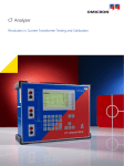
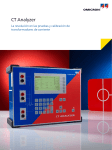
C T A n a ly z e r
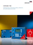
The Revolution in
Current Transformer Testing
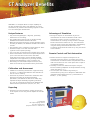
The Unique Solution
OMICRON’s CT Analyzer is a unique lightweight electronic
multifunctional instrument designed to meet the highest
standards for performing excitation, ratio, polarity and
winding resistance tests on current transformers (CTs) as
well as burden-impedance measurement.
The equipment provides automatic testing and calibration for
all types of low leakage flux current transformers both on-site
in the power system as well in the controlled environment of
CT and switchgear manufacturers.
The CT Analyzer allows an automatic assessment of test results
clearly indicating whether the parameters of the CT under test
match its specification. It is the only known device able to
test and assess CTs build according IEC60044-6 with defined
transient performance (TPS, TPX, TPY and TPZ).
Because of the patented (EP 1 398 644 A1) low voltage test
method it is possible to test CTs with a knee point voltage up
to 15 kV without stressing the insulation of the CT (max.
120 V test voltage).
Testing of current transformers can be carried out to an
extremely high level of accuracy. The accuracy level (0.02 % /
1 min.) makes the CT Analyzer the ideal tool for calibration
and verification, not only for protection CTs but also for class
0.1 CTs for metering.
8
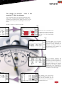
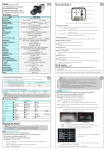
In the final step, the “CT-Object”
card shows the measured values for
rated primary and secondary current,
the CT class and the CT designation;
“M” for a measurement CT or "P"
for a protection CT; VA (nominal
burden), Burden (operating Burden)
and CosPhi. All results are stored on
the Compact Flash card and can be
easily transferred to a PC.
7
The "Phase Table" shows
the phase error at
nominal burden and at
different currents and at
25 %, 50 % and 100 %
of rated power.
A wide range of measurement functionalities can be provided:
• Burden measurement
• CT Winding resistance measurement
• CT Excitation characteristic recording
• CT transient behavior measurement (IEC60044-6)
• CT ratio measurement with consideration of connected
burden
• CT phase and polarity measurement
•
Determination of accuracy limiting factor (ALF), instrument security factor (FS), secondary time constant (Ts), remanence factor (Kr), transient dimensioning factor (Ktd), knee point voltage/current, class, saturated and non saturated inductance
• Assessment according to defined standards: IEC60044-1, IEC60044-6, IEEE C57.13-1993
The extremely small and lightweight (< 8 kg / 17 lb) hardware
is particularly beneficial for on-site testing.
6
The "Ratio Table" shows
ratio error at nominal
burden and at different
currents and at 25 %,
50 % and 100 % of the
rated power.
5
The ratio error, phase error and
composite error for the operating
burden can now be measured and
displayed.
The results in seconds - even if the
nominal CT data is unknown
The CT Analyzer performs an automatic parameter search
and CT test - using the "Name plate guesser" function. For
standard current transformers it allows the user to do a test
with minimal training and no knowledge of the CT to be
tested.
All that is needed is to follow these steps:
1
Connect the CT as indicated on the
CT Analyzer front panel, activate the
CT-object card on the user interface
and start a CT test with default
settings.
2
The device applies a 1A DC current
to the secondary terminals of the CT
and runs the fully automated test
procedure - no settings are necessary.
The Resistance Card displays the
measured resistance (R ct).
3
4
The CT Analyzer measures the
excitation curve and determines the
knee point and other important CT
data. Depending on the value of the
knee point voltage the CT Analyzer
identifies the test object as either a
measurement CT or a protection CT
and determines the nominal burden if
not defined in the object page.
The excitation curve derived from
the test is displayed on the unit. This
curve can be compared with the
result of a previous test loaded from
a Compact Flash card.
CT Analyzer Functionality
CT-Object
The CT-Object card is the central element within the user
interface which contains all of the necessary test settings for
a CT test. Data is provided in the following fields:
Completely edited CT-Object card
•
•
•
•
•
•
•
I-pn / I-sn: Rated primary / secondary current
Std: Standard to which the test is to be performed
P / M: CT type definition: protection or measurement
Class / Freq: Class and rated frequency of CT
VA: Rated burden
Burden / cos ϕ: Operating burden and cos ϕ
more: extended parameter page for IEC 60044-6 and
IEC60044-1 class PX CTs
Extended Object Page
The extended object page is used to enter class dependent
parameters for assessment or for the calculation of the
transient behavior according IEC60044-6.
Following parameters can be found on this page:
Extended CT-Object page
•
•
•
•
•
•
•
•
•
Kssc: rated symmetrical short circuit current factor
Ktd: transient dimensioning factor
Vkn: knee-point voltage according to IEC 60044-6
Ikn: knee-point current according to IEC 60044-6
Ts, Tp (secondary and primary time constant)
Seq (duty of the protection )
tal1, tal2, t1, t2, tfr (timing parameters for duty)
Rct (expected winding resistance)
Ek/Ual, Ie, Ial (accuracy limiting voltage and current)
Burden Test
The Burden Test Card allows the measurement of a current
transformer’s secondary burden by injecting AC current into
the load (up to 5 A). The results of the burden test are shown
on the display as follows:
• I-meas / V-meas: Current and voltage measured during the test
• Burden / cos ϕ / Z: Calculated values
Results of the burden measurement
Resistance Test
The CT winding resistance is needed for several calculations in
the excitation and ratio test. During the test a DC current is
applied to the CT until saturation is reached. The following
results are shown on the Resistance card:
• I-DC / V-DC: Measurement current and voltage
• R-meas: Measured resistance
• R-ref: Temperature compensated resistance
Results of the CT winding resistance measurement
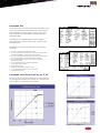
Excitation Test
The Excitation test measures and displays the excitation curve
of the current transformer and determines a wide range of
other parameters of the CT using a current of up to 15 A
peak. Parameters are calculated for nominal burden and
operating burden.
According to the selected standard, terminal voltage,
emf voltage, rms current or peak current is shown on the
excitation graph.
Depending on the selected standard the corresponding
results are:
• V-kn / I-kn: Knee point voltage and current
• FS / ALF: Instrument Security Factor or Accuracy Limiting Factor
according IEC60044-1 direct measurement method
• FSi / ALFi: Instrument Security Factor or Accuracy Limiting Factor
according IEC60044-1 indirect measurement method
• Kssc, Ktd: Symmetrical short circuit current and transient
dimensioning factor
• Ls / Lu: Saturated and non saturated inductivity
• Ts: Secondary time constant
• Kr: Remanence factor
• Val/Ial accuracy limiting voltage / current
• ε^ peak instantaneous error at Ipn * Kssc*Ktd
• E-max: Maximum e.m.f.
Excitation curve from 1 mV up to 17 kV
Test of CT's with a knee point voltage up to 15 kV. Only with
our patented low frequency test principle it is possible to test
such CTs without overstressing the insulation.
Excitation test up to 12.7 kVA on TPZ
Excitation test up to 15 kV
Excitation curve down to 1 mV
Ratio Test
The ratio test measures the current ratio of the CT with
consideration of the external burden or the rated power.
No external burden is necessary, burden is part of modeling
therefore a recalculation of current error with different
burden is also possible after the test. The results from the
ratio test are displayed on the screen in different cards:
Results shown
on the
Ratio Card
• The Ratio card shows the polarity, the turns ratio error,
composite error, current ratio error and the phase
displacement dependent on primary current and
operating burden (defined in the CT-Object card).
• The Ratio table shows the current ratio error dependent
on current and the nominal burden
• The Phase table shows the phase displacement dependent
on current and nominal burden.
After the measurement is completed, the Ratio card allows
the burden and / or primary current (I-p) to be changed to
allow the effect on the ratio and / or phase error to be
observed. Possibility to compensate the ratio error of a CT
used within a delta connected Transformer. All results that are
visible on the screen will be stored automatically in the test
result file
Assessment
The Assessment card shows the automatic and manual
assessment of the CT as a result of the testing.
Results shown on the Assessment Card
The automatic assessments are based on a comparison of
the measured values to the requirements of the selected
standard and the selected parameters on the CT-Object card.
Additionally a manual assessment can be done.
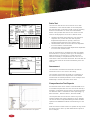
Comprehensive Test Reports
All measured results can be saved as a standard XML file on
a removable Compact Flash card. This card can be read by a
Windows™ PC allowing the test report to be easily imported
into Microsoft Office™ software for further processing (e.g.
Microsoft Excel™, Microsoft Word™, Microsoft HTML).
The Compact Flash card can also be used for any future
software updates that may be required for the CT Analyzer.
This can be carried out by downloading the latest firmware
updates from OMICRON's website and transferring it to the
device.
Abstract of the test report viewed within the CPC Explorer
With the reomote control interface it's possible to fully control
the device from PC and to up and download test reports to
the CT Analyzer.
Support for IEC60044-6
CT-Analyzer is the only probably device available on the
market that allows the test of CT's according IEC 60044-6.
The measurement is done according the standard (low
frequency) and delivers all parameters that are relevant for
the IEC60044-6 standard as Kssc, Ktd, εt, ε^, Vkn, Ikn
under consideration of duty cycle and misc. time constants.
After the test the device allows to assess if the CT fulfills the
specified timing requirements or not.
CT-Analyzer does all the calculation necessary to deliver the
transient dimensioning factor.
Calculation of Ktd without remanence according
IEC60044-6 and with remanence (Ktd OMICRON)
Remote control interface for full
production integration
With the remote software it is possible to integrate the device
in a fully automatic test environment or to write the own
customer specific User Interface. Excel File Loader or Remote
Excel File loader allows to import the XML output files
from CT-Analyzer into Excel and to build customer specific
test reports. For an easy start in working with the remote
interface working samples are delivered with the device.
CTA QuickTest
The CTA Quick Test is a PC Tool to do a large variety of
measurements usually necessary in a utility by using CT
Analyzer as Multimeter with integrated current/voltage source
(measurement of Burden, L, C, ratio, polarity, etc)
CT Analyzer Benefits
OMICRON´s CT Analyzer delivers a unique capability for
the fast comprehensive testing and calibration of current
transformers, for protection and metering engineers as well
as CT and switchgear manufacturers.
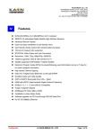
Unique Features
Advantage of Simulation
•Very small and lightweight (< 8kg/17lb), particularly
beneficial for on-site testing.
•First portable device that can test CTs build according
IEC60044-6 with defined transient behaviour.
•Reduced commissioning time due to fully automatic testing
according EC 60044-1, IEC 60044-6 and IEEE C57.13 within
seconds.
•Save operation due to a maximum output voltage of 120 V.
•Automatic analysis of CTs with unknown data
("guesser" function patent pending).
•Test of CTs with very high knee point voltages (up to 15 kV)
•Precise measurement of ratio error and phase displacement
up to x-times the rated current and for all burden
values without the need to connect burden hardware,
independent of the application (e.g. bushings and GIS).
•Automatic demagnetization of the CT after the test.
•Data storage on a removable Compact Flash (CF) card,
which can be read by any standard memory card reader.
•Existing test reports can be loaded at any time to
recalculate the test results for different burden values
and primary currents. This way, no further on-site
measurements are necessary to verify whether a changed
burden influences the behavior of a CT. The recalculation
of the test results can be easily performed in the laboratory
using the existing measurement data either on the
CT-Analyzer, within Excel File Loader or by using the remote
control interface.
Calibration and Assessment
•Calibration of measuring transformers: A typical accuracy
of 0.02 % / 1’ enables field calibration and verification of
class 0.1 CTs for metering.
•Assessment of protection transformers: Automatic result
assessment according to the defined standard
(IEC 60044-1, IEC 60044-6 or IEEE C57.13-1993) using
implemented expert knowledge (regarding standards,
etc.) even for CTs defined according to IEC 60044-6 with
defined transient performance (TPS, TPX, TPY, TPZ).
Reporting
•Automatic test report generation. Viewing and printing
of test reports on a PC using the CPC Explorer or Excel File
Loader.
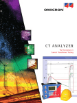
CT ANALYZER
The unique analyzing solution
for current transformers.
[European Patent EP 1 398 644 A1]
Remote Control and Test Automation
•Remote interface to integrate CT-Analyzer into an
automatic production process. CT-Analyzer can fully be
controlled over the remote interface. All parameters can be
read from the device or from a test report with a simple to
use software interface.
•Possibility to create user defined test reports using the
Excel File Loader by adaptation of sample software running
under visual basic or C++.
•The "CTA Quick Test" enables a large variety of
measurements by using the CT Analyzer as Multimeter with
integrated current/voltage source (e.g. measurement of
Burden, L, C, ratio, polarity).
Measurement of CT parameters
General
•Ls (saturated inductance)
•Lu (unsaturated inductance)
•Kr (remanence flux)
•Ts (secondary time constant)
•Rct (winding resistance)
•current ratio error and phase error for all measurement
points defined in the standard
•Ratio up to 50 000 : 1
•Primary current up to 999 000 A
IEC 60044-1
•ALF/ALFI (accuracy limiting factor according direct /
indirect measurement method)
•FS/FSI (instrument security factor according direct /
indirect measurement methode)
•Kx (dimensioning factor according to class PX)
•Ek / Ie (accuracy limiting voltage/current according
to class PX)
•N (turns ratio according to class PX)
•εt , εc (turns ratio and composite error)
•Vkn / Ikn (knee-point voltage/current according
to IEC 60044-1)
IEC 60044-6
•Kssc (rated symmetrical short-circuit current factor)
•Ktd (transient dimensioning factor)
•N (turns ratio according to class TPS)
•εt (turns ratio error according to class TPS)
•ε^ (peak instantaneous error)
•Emax (maximum emf voltage incl. the transient
component)
•Vkn / Ikn (knee-point voltage/current according
to IEC 60044-6)
IEEE C57.13 (ANSI)
•Vb (secondary terminal voltage rating according to
IEEE C57.13)
•Vkn / Ikn (knee-point voltage/current according to
IEEE C57.13 (30° and 45° tangent))
Technical Data
OMICRON’s CT Analyzer hardware includes:
•Galvanically insulated electronic generator output
•Two galvanically insulated voltage measurement inputs
•Internal current measurement
•Compact flash card to store test results and update the
device software
The CT Analyzer conforms to CE and fulfills the requirements
of IEC in terms of EMC and safety standards.
Hardware Specifications
Generator / amplifier section
Output current
0 ... 5 A rms (15 A peak)
Output voltage
0 ... 120 V
Output power 0 ... 400 VA (1500 VA peak)
Ratio accuracy
For 0 VA up to rated power
ratio 1 ... 2000
0.02 %
ratio 2000 ... 5000
0.03 %
ratio 5000 ... 10000
0.05 %
Phase measurement
Resolution
Accuracy
0.1 min
1 min (for cos ϕ 0.8 ... 1)
User interface
Display readable in bright sunlight.
Numerical keyboard and function keys for operation.
Data transfer
Compact flash card to store test results and for transfer of data to
a PC. Data can be read with a standard PC and the CPC explorer.
Remote interface toe read/write data from PC and to fully control the
device with the PC.
Standards
Safety EN60950 and EN61010
Calibration
It is possible to buy a calibration CT certified from a national test
institute with a ratio accuracy of 0.02 %. With this calibration CT a
permanent check of the CT-Analyzer accuracy is possible. The device
must not be sent back for calibration, only the calibration CT.
Mechanical Data
Weight Dimensions (W x H x D)
8 kg / 17.4 lb (without accessories)
360 x 285 x 145 mm / 9.2 x 7.2 x 3.7 in.
Supply voltage
Nominal voltage Permissible range 110 V – 240 V ±10 % 50 / 60 Hz (500 VA)
85 V – 265 V
Ambient temperature
-10 … 50 °C / 14 ... 122 °F
10
Ordering Information
CT Analyzer CT1 incl. accessories VE000652
CT Analyzer standard package Accessories set for CT Analyzer VE000650
VEHK0650
CT Analyzer standard package VE000650
CT Analyzer hardware Compact Flash card 128 MB (memory space for at least 416 test reports)
USB 2.0 Compact Flash card reader USB - RS232 Converter and Cable
RS232 Nullmodem Cable 3m Power cord (country-dependent)
User Manual CT Analyzer PC Toolset software for CT Analyzer with remote control software, CTA Quick Test,
CT Excel File Loader and other tools. CPC Explorer software, PC software for visualization and handling of test reports
VEGG0650
VEHZ0653
VEHZ0655
VEHZ0014
VEHK0032
VESD0605
VESM0800
VESD6004
Accessories set for the CT Analyzer
VEHK0650
Coax measurement cable set with banana plugs, 2 x 3 m, 1 x 10 m
Battery clamp set with 4mm banana sockets for primary side connection, consisting of one red
and one black battery clamp Crocodile clamp set (2 x red, 2 x black), 20 mm opening width Grounding (PE) cable (gn/ye), 1 x 6 m, 6 mm2, used for protective earth connection
Flexible terminal adapters with 4 mm banana socket (6 x)
Carry bag for the CT Analyzer VEHK0651
VEHZ0652
VEHZ0656
VEHK0615
none
VEHP0018
Additional Accessories for CT Analyzer
Coax measurement cable with banana plugs, 3 m VEHK0654
Coax measurement cable with banana plugs, 6 m VEHK0652
Coax measurement cable with banana plugs, 10 m VEHK0653
Coax measurement cable with banana plugs, 15 m VEHK0655
Coax measurement cable with banana plugs, 100 m E0521400
Crocodile clamp for secondary side connection with 4 mm banana socket (1 black and 1 red clamp) VEHZ0651
Transport case for the CT Analyzer with wheels VEHP0068
Calibration CT, 2000:1 / 2000:5, class 0.02 VEHZ0649
CT Analyzer Add-On Manual VESD0607
11
OMICRON is an international company providing innovative power system testing solutions. With
sales in more than 120 countries, offices in Europe, the North America, and Asia, and a worldwide
network of sales partners, OMICRON has established a reputation as a supplier of leading edge
technology.
OMICRON’s automated primary and secondary testing capabilities are important benefits in light
of the changing market conditions resulting in restructured organizations required to "do more
with less". Services in the area of consulting, commissioning, testing, and training make the
product range complete.
Specialization and visionary leadership allows OMICRON to continue with revolutionizing
developments for its solutions to meet the customer needs of the 21st century.
OMICRON Sales Service Centers
Europe, Middle East, Africa
OMICRON electronics GmbH
Oberes Ried 1
A-6833 Klaus, Austria
Phone: +43 5523 507-0
Fax: +43 5523 507-999
[email protected]
www.omicron.at
North and South America
OMICRON electronics Corp. USA
12 Greenway Plaza, Suite 1510
Houston, TX 77046, USA
Phone: +1 713 830-4660
1 800-OMICRON
Fax: +1 713 830-4661
[email protected]
www.omicronusa.com
Asia, Pacific
OMICRON electronics Asia Limited
Suite 2006, 20/F, Tower 2
The Gateway, Harbour City
Kowloon, Hong Kong S.A.R.
Phone: +852 2634 0377
Fax: +852 2634 0390
[email protected]
www.omicron.at
© OMICRON L053
Subject to change without notice
12