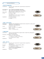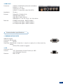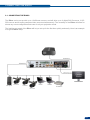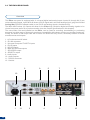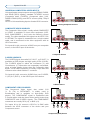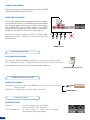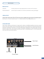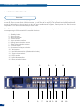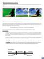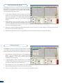
1
version 4.00
USER MANUAL
Eikos
THANK YOU
Thank you for choosing Analog Way. By following these simple steps, you should be able to operate
the powerful Eikos (EKS500).
TABLE OF CONTENTS
1
INTRODUCTION
5
1-1. EIKOS OPERATING MODES
5
Mixer Mode
Matrix Mode
Quadravision Mode
1-2. USEFUL TERMS AND DEFINITIONS
HARDWARE INSTALLATION
2-1. SAFETY INSTRUCTION
6
7
7
2-2. UNPACKING AND INSPECTION
12
2-3. RACKMOUNT INFORMATION
12
2-4. CABLE & ADAPTOR INFORMATION
12
2-5. HARDWARE SPECIFICATIONS
13
Input specifications
Output specifications
Communication specifications
Environmental specifications
Pin outs
HDCP compliance
CONNECTING THE EIKOS
23
3-1. CONNECTING THE EIKOS
23
3-2. THE EIKOS REAR PANEL
24
Overview
Inputs #1 to #6
DVI Inputs #1 and #2
SD/HD-SDI Inputs #1 and #2
Preview Outputs
Main Outputs
1
OPERATING THE EIKOS
28
4-1. THE EIKOS FRONT PANEL
28
Overview
On/Off button
Menu screen
Menu scroll knob
Control section
Layer selection section
Input selection section
Freeze button
Adjustment
Toggle Preset
Take button
Quadravision selection button
Effect Selection button
Preset Selection button
4-2. THE EIKOS MENU
31
Menu navigation
Home menu
4-3. WORKING WITH THE EIKOS
32
Operating modes
Reseting default values
Eikos color codes
• A- Settings in Mixer Mode
Source Input selection
Input selection settings
Input Sync. Loss Function
Source output selection
Output selection settings
Preview Features
Preview Mode & OSD Settings
Preview Id
How to use the Mosaic Preview Feature
Working with Layers
Working with Layers Functions
Opening transitions and closing Live Layers
Working with PIPs
PIP adjustment menu
PIP configuration
PIP as Layers
PIPs with Transitions & Borders
Capturing still Frames
Working with Frames
Opening transitions & closing Still Layers
Memorizing Frames
Frame input setup menu
Frames as Layer
Layer Transitions & effects
Mixer Functions
Capturing Logos
Capturing an Animated Logo
Memorizing Logos
Logos input setup menu
Working with Logos
Logos as Layers
Working with Presets
2
34
Creating Presets
Working with audio
Audio configuration
Special Features
• B- Settings in Native Matrix Mode
53
Source Input selection
Input selection settings
Working with Layers
Source Output selection
Output selection settings
Working with Native Matrix Mode
Working with Cut, Fade or Transitions
Working with PIP
Working with Mirror Mode
Working with Frames/Logos
• C- Settings in Quadravision Mode
58
Working with Templates
Working with Presets
Creating a Preset
Working with Frames/Logos
HOME MENU
61
REMOTE CONTROL SOFTWARE
70
5-1. THE EIKOS RCS
70
RCS presentation
How to use the RCS
Software installation
Software overview
Serial connection
Ethernet connection
5-2. WORKING WITH THE RCS
73
Operating Mode
Source input configuration
Source output configuration
Working with PIPs
PIP configuration
Working with Frames
Memorizing Frames
Working with Logos
Memorizing Logos
Layer transitions & effects
Creating Presets
Working with Presets
Working with Audio
Audio configuration
3
OPTIONAL REMOTE CONTROL SYSTEMS
6-1. Axion 2 - Ref. ARC200
78
6-2. Orchestra - Ref. ORC50
79
6-3. TRK-800 - Ref. TRK-800
80
6-4. RK-300 - Ref. RK-300
81
APPLICATION NOTES AND TIPS
82
7-1. ABOUT APPLICATION NOTES
82
7-2. APPLICATION NOTES
82
7-3. EXTERNAL PROGRAMMING
86
WARRANTY AND SERVICES INFORMATION
87
8-1. ANALOG WAY LIMITED WARRANTY
87
8-2. SERVICES AND RMA
87
CONTACT INFORMATION
4
78
88
HOW TO CONTACT US
88
INFORMATION ON DISPOSAL
88
INTRODUCTION
1-1. THE EIKOS (EKS500) OPERATING MODES
Before you start setting up your Eikos for the first time, be sure you know what you actually want to do with
it. The Eikos offers a choice of three operating modes, which results in a versatile video production tool for
live event staging and fixed installation applications.
* NOTE * : We recommend resetting the device to its default values every time you set up your shows or
events (see the “Operating The Eikos” chapter, p28).
MIXER MODE
This mode allows for a single Eikos to seamlessly switch and blend any of its 12 analog/digital inputs with
any other of the inputs, add PIP, titling or logo insertion to the live frame, while previewing your every move
before going live, to avoid embarrassing errors on your main screen. The Mixer mode is the Eikos native
mode, and with no less than 6 layers (of which 3 live layers). The Video output of the Eikos allows to have a
full Main screen for recording or broadcasting.
MATRIX MODE
This mode turns your Eikos into a true 12 x 2 scaled matrix, while preserving seamless switching capabilities.
Main and Preview outputs can be set to different resolutions and rates. Switching between any of the inputs
can be done with the various effects (Cut, Fade, Slides…) and synchronized on both outputs.
QUADRAVISION MODE
This mode allows to display up to four live windows, while preserving seamless switching capabilities. Several
templates are available.
5
1-2. USEFUL TERMS AND DEFINITIONS
BACKGROUND: a “Background” is a source, typically originating from a computer. Eikos enables you to
work with live or still (frame) background sources - visually in back of all other sources.
LAYER: a “Layer” is an image display element (such as a PIP window, Key, Logo(s) or Background) that has
an associated visual priority — either in front (or in back) of another layer.
The Eikos can simultaneously view no less than 6 layers (3 video, or live layers, 1 frame layer, or background,
and 2 logo layers).
Eikos can insert up to 2 PIPs on a live background, plus 2 logos.
PIP: a “PIP” (Picture In Picture), is a picture, typically of reduced size, which is positioned over another
background image or PIP. PIPs can be reduced, enlarged and bordered. PIPs can overlap, depending on
their visual priority.
Eikos allows for Dynamic PIP on the opening and closing of the sequence, vertically or horizontally. A “flying”
PIP is also possible over the screen with vertical, horizontal or diagonal animation. A PIP is considered as a
live layer.
FRAME: a “Frame” is a full screen image which is selected from one of the eight still frames which you can
capture with the Eikos. A Frame can be flash captured and imported from any video or computer source
plugged into the machine.
LOGO: a “Logo” is a part of screen image that can be flash captured and imported from any Video or
Computer source, by keying or image cut-out. Eikos can record up to 8 still logos. They can be positioned
anywhere on the screen. An animated logo is also available on the eighth input.
KEYING: a “Key” is an electronic process whereby an image is electronically superimposed over another
source or background, by cutting out either a color Chroma Key), or its brightness or luminance levels (Luma
Key). Keys are typically used for titles, logos and special effects.
Eikos allows to use a live source with green or blue background and to key it over any other live input.
6
HARDWARE INSTALLATION
2-1. SAFETY INSTRUCTIONS
SAFETY INSTRUCTIONS
CAUTION:
All of the safety and operating instructions should be read before the product is operated and should be
maintained for further reference. Please follow all of the warnings on this product and its operating instructions.
•
WARNING: To prevent the risk of electric shock and fire, do not expose this device to rain, humidity,
intense heat sources (such as heaters and direct sunlight). Slots and openings in the device are provided
for ventilation and to avoid overheating. Make sure the device is never placed near a textile surface that
could block the openings. Also keep away from excessive dust, vibrations and shocks.
•
POWER: Only use the power supply indicated on the device of the power source. Devices equipped with
a grounding plug should only be used with a grounding type outlet. In no way should this grounding be
modified, avoided or suppressed.
•
POWER CORD: The device is equipped with a main switch (On (I) /Off (O)). The Switch ON and OFF is
initiated by the main switch.
Caution: The power cord constitute the only mean to totaly disconnect the equipment
from the main power.
Apply the following guidelines :
- The equipment connected to the network must have a release system easily
accessible and located outside the unit.
- Unplug the power cord, do not pull on the power cord but always on the plug itself.
- The outlet should always be near the device and easily accessible.
- Power supply cords should be routed so that they are not likely to be walked on or
pinched by items placed upon or against them.
If the power supply cord is damaged, unplug the device. Using the device with a damaged power supply cord
may expose your device to electric shocks or other hazards. Verify the condition of the power supply cords
once in a while. Contact your dealer or service center for replacement if damaged.
•
CONNECTIONS: All inputs and outputs (except for the power input) are TBTS defined under EN60950.
•
SERVICING: Do not attempt to service this product yourself by opening or removing covers and screws
since it may expose your device to electric shocks or other hazards. Refer all problems to qualified
service personnel.
•
OPENINGS: Never push objects of any kind into this product through the openings. If liquids have been
spilled or objects have fallen into the device, unplug it immediately and have it checked by a qualified
technician.
7
INSTRUCTIONS DE SECURITE
Afin de mieux comprendre le fonctionnement de cet appareil nous vous conseillons de bien lire toutes les
consignes de sécurité et de fonctionnement de l’appareil avant utilisation. Conservez les instructions de
sécurité et de fonctionnement afin de pouvoir les consulter ultérieurement. Respectez toutes les consignes
marquées dans la documentation, sur le produit et sur ce document.
•
ATTENTION: Afin de prévenir tout risque de choc électrique et d’incendie, ne pas exposer cet appareil à
la pluie, à l’humidité et aux sources de chaleur intense.
•
INSTALLATION: Veillez à assurer une circulation d’air suffisante pour éviter toute surchauffe à l’intérieur
de l’appareil. Ne placez pas l’appareil sur ou à proximité d’une surface textile susceptible d’obstruer
les orifices de ventilation. N’installez pas l’appareil à proximité de sources de chaleur comme un
radiateur ou une poche d’air chaud, ni dans un endroit exposé au rayonnement solaire direct, à des
poussières excessives, à des vibrations ou à des chocs mécaniques. Ceci pourrait provoquer un mauvais
fonctionnement et un accident.
•
ALIMENTATION: Ne faire fonctionner l’appareil qu’avec la source d’alimentation indiquée sur l’appareil.
Les appareils doivent être obligatoirement connectés sur une source équipée d’une mise à la terre efficace.
En aucun cas cette liaison de terre ne devra être modifiée, contournée ou supprimée.
•
CORDON D’ALIMENTATION: Les appareils sont équipés d’un interrupteur général (Marche I / Arrêt
O), la mise en tension et la mise hors tension se fait en actionnant cet interrupteur général. Attention :
le cordon d’alimentation constitue le seul moyen de débrancher l’appareil totalement de l’alimentation
secteur. Pour être certain que l’appareil n’est plus alimenté, ce cordon doit être débranché de la prise
murale.
Appliquer les consignes suivantes :
- Le matériel relié à demeure au réseau, doit avoir un dispositif de sectionnement facilement accessible
qui doit être incorporé à l’extérieur de l’appareil.
- Débrancher le cordon d’alimentation de la prise murale si vous prévoyez de ne pas utiliser l’appareil
pendant quelques jours ou plus.
- Pour débrancher le cordon, tirez-le par la fiche. Ne tirez jamais sur le cordon proprement dit.
- La prise d’alimentation doit se trouver à proximité de l’appareil et être aisément accessible.
- Ne laissez pas tomber le cordon d’alimentation et ne posez pas d’objets lourds dessus.
Si le cordon d’alimentation est endommagé, débranchez-le immédiatement de la prise murale. Il est
dangereux de faire fonctionner un appareil avec un cordon endommagé; un câble abîmé peut provoquer un
risque d’incendie ou un choc électrique. Vérifiez le câble d’alimentation de temps en temps. Contactez votre
revendeur ou le service après-vente pour un remplacement.
8
•
CONNEXIONS: Toutes les entrées et sorties (exceptée l’entrée secteur) sont de type TBTS (Très Basse
Tension de Sécurité) définies selon EN 60950.
•
RÉPARATION ET MAINTENANCE: L’utilisateur ne doit en aucun cas essayer de procéder aux opérations
de dépannage, car l’ouverture des appareils par retrait des capots ou de toutes autres pièces constituant
les boîtiers ainsi que le dévissage des vis apparentes à l’extérieur, risquent d’exposer l’utilisateur à des
chocs électriques ou autres dangers. Contactez le service après-vente, votre revendeur ou s’adresser à
un personnel qualifié uniquement.
•
OUVERTURES ET ORIFICES: Les appareils peuvent comporter des ouvertures (aération, fentes, etc...),
veuillez ne jamais y introduire d’objets et ne jamais obstruer ses ouvertures. Si un liquide ou un objet
pénètre à l’intérieur de l’appareil, débranchez immédiatement l’appareil et faites-le contrôler par un
personnel qualifié avant de le remettre en service.
INSTRUZIONI DI SECUREZZA
Allo scopo di capire meglio il funzionamento di questa apparecchiatura vi consigliamo di leggere bene
tutti i consigli di sicurezza e di funzionamento prima dell’utilizzo. Conservare le istruzioni di sicurezza e di
funzionamento al fine di poterle consultare ulteriormente. Seguire tutti i consigli indicati su questo manuale
e sull’apparecchiatura.
•
ATTENZIONE: Al fine di prevenire qualsiasi rischio di shock elettrico e d’incendio, non esporre
l’apparecchiatura a pioggia, umidità e a sorgenti di eccessivo calore.
•
INSTALLAZIONE: Assicuratevi che vi sia una sufficiente circolazione d’aria per evitare qualsiasi
surriscaldamento all’interno dell’apparecchiatura. Non collocare l’apparecchiatura in prossimità o su
superfici tessili suscettibili di ostruire il funzionamento della ventilazione. Non installate l’apparecchiatura
in prossimità di sorgenti di calore come un radiatore o una fuoruscita d’aria calda, né in un posto esposto
direttamente ai raggi del sole, a polvere eccessiva, a vibrazioni o a shock meccanici. Ció potrebbe
provocare un erroneo funzionamento e un incidente.
•
ALIMENTAZIONE: Far funzionare l’apparecchiatura solo con la sorgente d’alimentazione indicata
sull’apparecchiatura. Le apparecchiature queste devono essere obbligatoriamente collegate su una
sorgente fornita di una efficiente messa a terra. In nessun caso questo collegamento potrà essere
modificato, sostituito o eliminato.
•
CAVO DI ALIMENTAZIONE: Gli apparecchi con un interrutore (commutatore) generale
(Accesso I : Speuto 0), accendere ou spagnere l’apparecchio si fa usando l’interrutore.
Attenzione: il cavo di alimentazione è il solo modo di disconnettere l’apparecchio dell’alimentazione. Per
assicurarsi che totalemente l’apparecchio non è più collegato, il cavo deve essere disconesso della presa
murale.
Seguire le instruzioni seguenti :
- Il materiale collegato a residenza alla rete, deve avere un dispositivo di sezionamento facile da
raggiongere eche deve essere inserito all’esterno del apparecchio.
- Disconnettere l’apparecchiatura dalla presa murale se si prevede di non utilizzarla per qualche giorno.
- Per disconnettere il cavo tirare facendo forza sul connettore.
- La presa d’alimentazione deve trovarsi in prossimità dell’apparecchiatura ed essere facilmente
accessibile.
- Non far cadere il cavo di alimentazione né appoggiarci sopra degli oggetti pesanti.
Se il cavo di alimentazione é danneggiato, spegnere immediatamente l’apparecchiatura.
E’ pericoloso far funzionare questa apparecchiatura con un cavo di alimentazione danneggiato, un cavo
graffiato puó provocare un rischio di incendio o uno shock elettrico. Verificare il cavo di alimentazione
spesso. Contattare il vostro rivenditore o il servizio assistenza per una sostituzione.
•
CONNESSIONE: Tutti gli ingressi e le uscite (eccetto l’alimentazione) sono di tipo TBTS definite secondo
EN 60950.
•
RIPARAZIONI E ASSISTENZA: L’utilizzatore non deve in nessun caso cercare di riparare l’apparecchiatura,
poiché con l’apertura del coperchio metallico o di qualsiasi altro pezzo costituente la scatola metallica,
nonché svitare le viti che appaiono esteriormente, poiché ció puó provocare all’utilizzatore un rischio di
shock elettrico o altri rischi.
•
APERTURE DI VENTILAZIONE: Le apparecchiature possono comportare delle aperture di ventilazione,
si prega di non introdurre mai oggetti o ostruire le sue fessure. Se un liquido o un oggetto penetra
all’interno dell’apparecchiatura, disconnetterla e farla controllare da personale qualificato prima di
rimetterla in servizio.
9
SICHERHEITSHINWEISE
Um den Betrieb dieses Geräts zu verstehen, raten wir Ihnen vor der Inbetriebnahme alle Sicherheits
und Betriebsanweisungen genau zu lesen. Diese Sicherheits- und Betriebsanweisungen für einen
späteren Gebrauch sicher aufbewahren. Alle in den Unterlagen, an dem Gerät und hier angegebenen
Sicherheitsanweisungen einhalten.
•
ACHTUNG: um jegliches Risiko eines Stromschlags oder Feuers zu vermeiden, das Gerät nicht Regen,
Feuchtigkeit oder intensiven Wärmequellen aussetzen.
•
EINBAU: Eine ausreichende Luftzufuhr sicherstellen, um jegliche Überhitzung im Gerät zu vermeiden.
Das Gerät nicht auf und in Nähe von Textiloberflächen, die Belüftungsöffnungen verschließen können,
aufstellen. Das Gerät nicht in Nähe von Wärmequellen, wie z.B. Heizkörper oder Warmluftkappe,
aufstellen und es nicht dem direkten Sonnenlicht, übermäßigem Staub, Vibrationen oder mechanischen
Stößen aussetzen. Dies kann zu Betriebsstörungen und Unfällen führen.
•
STROMVERSORGUNG: Das Gerät nur mit der auf dem Gerät bezeichnete Stromquelle betreiben. Gerät
mit geerdeter Hauptstromversorgung muss an eine Stromquelle mit effizienter Erdung angeschlossen
werden. Diese Erdung darf auf keinen Fall geändert, umgangen oder entfernt werden.
•
NETZKABEL: Da die Geräte über einen Hauptschalter (An I/ Aus 0) verfügen, erfolgt die Stromversorgung
und -unterbrechung über diesen Hauptschalter.
Achtung : Das Netzkabel stellt die einzige Möglichkeit dar, das Gerät vollständig vom Netzanschluss
zu trennen. Um sicherzustellen, dass das Gerät nicht mehr versorgt wird, muss dieses Kabel aus der
Netzsteckdose ausgesteckt werden.
Bitte beachten Sie die folgenden Hinweise :
- Wenn Geräte dauerhaft am Netz bleiben, müssen sie über eine leicht zugängliche Trennvorrichtung
verfügen, die außen am Gerät angebracht sein muss.
- Das Kabel mittels dem Stecker herausziehen. Niemals am Stromkabel selbst ziehen.
- Die Steckdose muß sich in der Nähe des Geräts befinden und leicht zugänglich sein.
- Das Stromkabel nicht fallen lassen und keine schweren Gegenstände auf es stellen.
Wenn das Stromkabel beschädigt ist, das Gerät sofort abschalten. Es ist gefährlich das Gerät mit einem
beschädigten Stromkabel zu betreiben; ein abgenutztes Kabel kann zu einem Feuer oder Stromschlag
führen. Das Stromkabel regelmäßig untersuchen. Für den Ersatz, wenden Sie sich an Ihren Verkäufer
oder Kundendienststelle.
10
•
ANSCHLÜSSE: Bei allen Ein- und Ausgängen (außer der Stromversorgung) handelt es sich, gemäß EN
60950, um Sicherheits Kleinspannunganschlüsse.
•
REPARATUR UND WARTUNG: Der Benutzer darf keinesfalls versuchen das Gerät selbst zu reparieren,
die Öffnung des Geräts durch Abnahme der Abdeckhaube oder jeglichen anderen Teils des Gehäuses
sowie die Entfernung von außen sichtbaren Schrauben zu Stromschlägen oder anderen Gefahren für den
Benutzer führen kann. Wenden Sie sich an Ihren Verkäufer, Ihre Kundendienststelle oder an qualifizierte
Fachkräfte.
•
ÖFFNUNGEN UND MUNDUNGEN: Die Geräte können über Öffnungen verfügen (Belüftung, Schlitze,
usw.). Niemals Gegenstände in die Öffnungen einführen oder die Öffnungen verschließen. Wenn eine
Flüssigkeit oder ein Gegenstand in das Gerät gelangt, den Stecker herausziehen und es vor einer neuen
Inbetriebnahme von qualifiziertem Fachpersonal überprüfen lassen.
INSTRUCCIONES DE SEGURIDAD
Para comprender mejor el funcionamiento de este aparato, le recomendamos que le acuidadosamente todas
las consignas de seguridad y de funcionamiento del aparato antes de usarlo. Conserve las instrucciones de
seguridad y de funcionamiento para que pueda consultarlas posteriormente. Respete todas las consignas
indicadas en la documentación, relacionadas con el producto y este documento.
•
CUIDADO: Para prevenir cualquier riesgo de choque eléctrico y de incendio, no exponga este aparato a
la lluvia, a la humedad ni a fuentes de calorintensas.
•
INSTALACIÓN: Cerciórese de que haya una circulación de aire suficiente para evitar cualquier
sobrecalentamiento al interior del aparato. No coloque el aparato cerca ni sobre una superficie textil que
pudiera obstruir los orificios de ventilación. No instale el aparato cerca de fuentes de calor como radiador
o boca de aire caliente, ni en un lugar expuesto a los rayos solares directos o al polvo excesivo, a las
vibraciones o a los choques mecánicos. Esto podría provocar su mal funcionamiento o un accidente.
•
ALIMENTACIÓN: Ponga a funcionar el aparato únicamente con la fuente de alimentación que se indica
en el aparato. Los aparatos deben estar conectados obligatoriamente a una fuente equipada con una
puesta a tierra eficaz. Por ningún motivo este enlace de tierra deberá ser modificado, cambiado o
suprimido.
•
CABLE DE ALIMENTACIÓN: Los equipos incluyan interruptor general de alimentación (Encender I /
Apagar 0), la puesta en marcha o desconexión se realiza por medio de este interruptor.
El cable de alimentación constituye el único medio de desconectar el aparato totalmente de la red eléctrica.
Para estar seguro de que el aparato no está más alimentado, este cable debe de ser desconectado de la
toma de corriente.
Aplicar las siguientes consignas:
- E
l material conectado a residencia a la red informática, debe de tener un dispositivo de seccionamiento
fácilmente accesible que debe de ser incorporado al exterior del aparato.
- Desconectar el aparato del enchufe mural si no piensa utilizarlo durante varios días.
- Para desconectar el cable, tire de la clavija. No tire nunca del cable propiamente dicho.
- El enchufe de alimentación debe estar cerca del aparato y ser de fácil acceso.
- No deje caer el cable de alimentación ni coloque objetos pesados encima de él.
Si el cable de alimentación sufriera algún daño, ponga el aparato inmediatamente fuera de tensión. Es peligroso
hacer funcionar este aparato con un cable averiado, ya que un cable dañado puede provocar un incendio o un
choque eléctrico. Verifique el estado del cable de alimentación de vez en cuando. Póngase en contacto con
su distribuidor o con el servicio de posventa si necesita cambiarlo.
•
CONEXIONES: Todas las entradas y salidas (excepto la entrada del sector) son de tipo TBTS (Muy Baja
Tensión de Seguridad) definidas según EN 60950
•
REPARACIÓN Y MANTENIMIENTO: Por ningún motivo, el usuario deberá tratar de efectuar operaciones
de reparación, ya que si abre los aparatos retirando el capó o cualquier otra pieza que forma parte de
las cajas o si destornilla los tornillos aparentes exteriores, existe el riesgo de producirse una explosión,
choques eléctricos o cualquier otro incidente. Contacte el servicio de posventa, a su distribuidor o dirigirse
con personal cualificado únicamente.
•
ABERTURAS Y ORIFICIOS: Los aparatos pueden contener aberturas (aireación, ranuras, etc.). No
introduzca allí ningún objeto ni obstruya nunca estas aberturas. Si un líquido o un objeto penetra al
interior del aparato, desconéctelo y hágalo revisar por personal cualificado antes de ponerlo nuevamente
en servicio.
11
2-2. UNPACKING AND INSPECTION
1 x Eikos (EKS500)
1 x Power supply cord.
2 x DVI male to HD15 female and DVI-D female
Breakout Cable
1 x HD15-M to 5 BNC-F cable
1 x Ethernet cross cable (for device update)
1 x Set of 11 audio 5 pin screw terminals
1 x RCS - Remote Control Software (PC only) *
4 x Screws for handle removal (M4x12mm)
1 x User manual
1 x Quick Start guide
WARNING !
If required, front handles of the device can be dismantled,
but with caution.
The original screws removed must not be reintroduced to
their location without handles in place.
Substantial damages can occur, including risk of electric shock from the mains voltage.
Only M4x12mm screws can be used.
(They are supplied with the unit)
* Download on our website: www.analogway.com
2-3. RACKMOUNT INFORMATION
Tabletop mounting: The Eikos can be used directly on a table, the unit is equipped with 4 handy anti-slip
rubber feet.
Rack mounting: The Eikos is compatible with a 19” enclosure. Please follow the instructions below to install
the device in a 19” rack.
Place the device in your rack. Attach the device to the rack by using 4 screws through the front panel holes
(screws not included).
Rear fixing is also recommended, in particular for permanent installations. The Eikos is equipped with drill
holes designed for compatibility with most rackmount braces.
Connect all of the cables of the device and attach them to the rack with the help of tie wraps.
IMPORTANT:
-The openings in the side and rear panels of the device are for cooling. Do not cover these openings to
avoid cutting air circulation.
-
Be sure that no weight in excess of 2 kg (4.4 Lbs.) is added onto the Eikos.
-
The maximum ambient operating temperature should not exceed 40°C (104°F).
-The rack and all mounted equipment in it must be reliably grounded according to national and/or local
electrical standards.
!
Dismantling front handles of the device could invalidate warranty on after sales services of your
Eikos. It is strongly advised to avoid using front handles as rests for your Eikos, they are designed
for manipulation purposes only.
If required, front handles of the device can be dismantled, but with caution. The original screws removed
must not be reintroduced to their location without handles in place. Substancial damages can occur,
including risk of electric shock from the main voltage. Only M4x12mm screws can be used. They are
supplied with the unit.
2-4. CABLE AND ADAPTOR INFORMATION
A large choice of cables and adaptors are compatible with the Eikos. To find which are to be used in your
setup, please refer to the Hardware Specifications chapter. Please contact your distributor for a list of available
cables and connectors for your Eikos.
12
2-5. HARDWARE SPECIFICATIONS
Description of the input formats supported by the device.
• SDTV
Standard
Size
Frame Frequency
Line Frequency
NTSC
525/480i
59.94Hz / 60Hz
15.735 KHz
PAL
625/576i
50Hz
15.625 KHz
SECAM
625/576i
50Hz
15.625 KHz
Standard
Size
Frame Frequency
Line Frequency
480p
525/480i
59.94Hz / 60Hz
31.47 KHz
576p
625/576i
50Hz
31.25 KHz
Standard
Size
Frame Frequency
Standard
720p
1280x720
50Hz / 59.94Hz / 60Hz
SMPTE 296M
1035i
1920x1035
59.94Hz / 60Hz
SMPTE 260M
1080i
1920x1080
50Hz / 59.94Hz / 60Hz
SMPTE 274M
1080p
1920x1080
23.97Hz / 24Hz / 25Hz / 29.97Hz / 30Hz
SMPTE 274M
1080sF
1920x1080
50Hz / 59.94Hz / 60Hz
SMPTE 274M
1080p
1920x1080
50Hz / 60Hz
HDTV
• EDTV
• HDTV (RGB or YUV)
• INPUT FEATURES
Inputs
Format
Signal
1
Connector
EDID
HD15#1
YES
2
SDTV
Analog SDTV
HD15#2
YES
3
EDTV
Analog EDTV
HD15#3
NO
4
HDTV
Analog HDTV
HD15#4
NO
5
Computer
Analog Computer
DVI#1: ANALOG PART
NO
DVI#2: ANALOG PART
NO
Digital SDTV (Except SDI)
Digital EDTV
DVI#1: DIGITAL PART
YES
Digital HDTV (Except SDI)
Digital Computer
DVI#2: DIGITAL PART
YES
Digital SDTV
BNC#1
NO
6
7
8
SDTV
EDTV
HDTV
Computer
9
10
SDTV
(SDI only)
BNC#2
NO
11
HDTV
Digital HDTV
BNC#3
NO
(SDI only)
BNC#4
NO
12
13
• COMPUTER FORMATS
The Eikos recognizes the following computer formats (Subsampled formats will be displayed with a degraded
quality. For a pixel clock > 165 MHz).
Format
Size
VGA
800x480
SVGA
WVGA
XGA
1152x864
1280x600
720p RGB
WXGA
800p RGB
960p RGB
SXGA
SWXGA
1360x1024
1366x768
DILA4/3
SWXGA+
SXGA+
900p RGB
1600x900
UXGA
WSXGA+
1080p RGB
WUXGA
1920x1440
2K
QXGA
Reduced Blankings
640x480
800x480
800x600
848x480
1024x768
1152x864
1280x600
1280x720
1280x768
1280x800
1280x960
1280x1024
1360x768
1360x1024
1366x768
1364x1024
1366x800
1400x1050
1440x900
1600x900
1600x1200
1680x1050
1920x1080
1920x1200
1920x1440
2048x1080
2048x1536
Subsampling
YES
YES
YES
YES
YES
• EDID
The EDID is available on inputs #1 & #2 and #7 & #8. The user can modify the EDID choosing from a list of
predefined formats and frequencies.
SETTING AND INPUT FUNCTIONS
Analog
Settings / Functions
1
2
3
DVI-D
4
5
6
Auto Settings
YES
YES
YES
YES
YES
YES
Auto Framing
1
YES
1
YES
YES
YES
Blanking Settings
YES
YES
YES
YES
Cropping
YES
YES
YES
Optimization
YES
YES
Under/Overscan
YES2
YES2
Aspect Ratio Settings
YES
YES
Aspect Input Output
YES
YES
Color Settings
YES
YES
1
1
8
9
10
11
12
YES
YES
N/A
N/A
N/A
N/A
YES
1
YES
NO
NO
NO
NO
NO
NO
YES
YES
NO
NO
NO
NO
NO
NO
YES
YES
YES
YES
YES
YES
YES
YES
YES
YES
YES
YES
YES
NO
NO
NO
NO
NO
NO
YES2
YES2
YES2
YES2
YES2
YES2
YES2
YES2
YES2
YES2
YES
YES
YES
YES
YES
YES
YES
YES
YES
YES
YES
YES
YES
YES
YES
YES
YES
YES
YES
YES
YES
YES
YES
YES
YES
YES
YES
YES
YES
YES
1
1
1
1
1
1
1
Advanced settings
YES
YES
YES
YES
YES
YES
NO
NO
NO
NO
NO
NO
2:2 Pulldown
YES3
YES3
YES3
YES3
YES3
YES3
YES3
YES3
YES3
YES3
YES3
YES3
3:2 Pulldown
YES4
YES4
YES4
YES4
YES4
YES4
YES4
YES4
YES4
YES4
YES4
YES4
1/ Analog Computer Input or Analog Video Input (EDTV or HDTV only)
3/ Only interlaced 50 Hz
14
SDI
7
2/ Only Video Input
4/ Only interlaced 59.94 Hz to 60 Hz
Input specifications
• ANALOG COMPUTER
Connectors: Inputs #1 to #4: female HD15. Inputs #5 & #6: female DVI-I
(analog pins).
Line frequency: Up to 130 kHz (165 MHz Max pixel rate).
Resolution: Up to 1600x1200 @ 165Mhz, 1920x1200px
(RB, Max V size: 1200px, Max H size 2048px).
Sync. types: RGBHV, RGB/S, RGsB (Sync On Green).
Levels: R, G, B = 0.7 Vp/p.
H & V Sync = TTL.
Composite Sync = TTL and 0.3 V (negative).
SOG (Sync On Green) = 0.3 V.
Impedance: R, G, B = 75 ohms.
H = 75 ohms or Hi-Z.
V = Hi-Z.
• RGB/S - RGsB VIDEO
Connectors: Inputs #1 to #4: female HD15. Inputs #5 & #6: female DVI-I (analog pins).
Frequency: 15.625 kHz - 50 Hz (625 lines).
15.734 kHz - 60 Hz (525 lines).
Levels:
R, G, B = 0.7 Vp/p.
SYNC. = 0.3 Vp/p or TTL (negative).
Impedance:
RGB = 75 ohms.
SYNC. = 75 ohms or Hi-Z.
• COMPONENT
Connectors: Inputs #1 to #4: female HD15. Inputs #5 & #6: female DVI-I (analog pins).
Input #8: female HD15.
Frequency:15.625 kHz - 50 Hz (625 lines).
15.734 kHz - 60 Hz (525 lines).
Levels:
Y = 1 Vp/p (0.7 V Luma + 0.3 V Sync.).
Cr / Pr & Cb / Pb = 0.7 Vp/p.
Impedance:
75 ohms.
• HDTV - HD-YUV
Connectors: Inputs #1 to #4: female HD15. Inputs #5 & #6: female DVI-I
(analog pins).
Formats: 720p/576p (60Hz), 1080i (50/60Hz), EDTV.
Levels: Y = 1 Vp/p (0.7 V + sync.).
Cr / Pr & Cb / Pb = 1 Vp/p (0.7 V + sync.).
Sync.:
Tri-level: ±0.3V (positive/negative).
Bi-level: 0.3V (negative).
Impedance:
75 ohms.
or
or
or
or
15
• S.VIDEO
Connectors: Standard:
Levels:
Impedance:
Inputs #1 to #4: female HD15. Inputs #5 & #6: female
DVI-I (analog pins).
PAL/SECAM: 15.625 kHz - 50 Hz - 625 lines.
NTSC (3.58 - 4.43 MHz): 15.734 kHz / 60 Hz / 525 lines.
Y = 1 Vp/p (0.7 V Luma + 0.3 V Sync.).
C = 0.3 Vp/p (Chroma Burst).
75 ohms.
or
• COMPOSITE VIDEO
Connectors: Inputs #1 to #4: female HD15. Inputs #5 & #6: female
DVI-I (analog pins).
RCA.Standard:PAL / SECAM: 15.625 kHz - 50 Hz - 625 lines.
NTSC (3.58 - 4.43 MHz): 15.734 kHz / 60 Hz / 525 lines.
Level:
1 Vp/p (0.7 V Luma + 0.3 V Sync.).
Impedance:
75 ohms.
or
• DVI (Digital Video Interface)
Connector:
DVI Inputs #1 & #2: female DVI-I (digital pins).
Line frequency: Up to 130 kHz (165 MHz Max pixel rate).
Format:
Digital Visual Interface (DVI)-TMDS single link.
Resolution: Up to 1600x1200 @ 165Mhz, 1920x1200px. (RB, Max V size: 1200px, Max H size 2048px).
• SD-SDI
Connector:
Format:
Data rate: Impedance:
SDI Inputs #1 to #4: female BNC.
SMPTE 259M-C.
270 Mbps serial digital.
75 ohms.
• HD-SDI
Connector:
Formats:
Data rate:
Impedance:
SDI Inputs #1 to #4: female BNC.
720p @ 50, 59.94 & 60 Hz.
1035i @ 50, 59.94 & 60 Hz.
1080i @ 50, 59.94 & 60 Hz.
1080p @ 23.97 / 24 / 25 / 29.97 / 30 / 50 & 60 Hz.
1080sF @ 50 / 59.94 & 60 Hz.
1.5 Gbps serial digital - SMPTE 292M-A.
2.97 Gbps serial digital - SMPTE 425M-A.
75 ohms.
• AUDIO
Input#
Stereo
Balanced Audio
Connectivity
YES
Connectors Phoenix 5 pins
Non applicable (Embedded Audio SDI)
Non applicable (Embedded Audio SDI)
YES
Connectors Phoenix 5 pins
1
2
3
4
5
6
7
YES
8
9
10
11
12
AUX
16
AUDIO SETTINGS
Settings
Availability
GAIN
YES: from -
Balanced Audio
YES: Left and Right
• Connector:
∞ to + 18dB
Balanced or unbalanced mono/stereo inputs
(all pin MCO male connector).
8 audio stereo inputs + 1 auxiliary.
(all balanced / unbalanced).
Vi = +15dBV max.
Zi = 40Kohms (Balanced).
MCO male connectors
Inputs #1 to #6: Balanced & unbalanced connection
Inputs DVI #1 to DVI #2: Balanced & unbalanced
connection
Input AUX: Balanced & unbalanced connection
4
L+
L-
LEFT
GROUND
RIGHT
R+
RUNBALANCED
Output specifications
Outputs #1 to #2: Balanced & unbalanced connection
4
• ANALOG OUTPUTS
Connector:Outputs #1 (Main) & #2 (Preview):
female HD15, DVI-I (analog pins).
L+
L-
L+
L-
GROUND(S)
R+
R-
R+
RBALANCED
Resolutions:
Format
Ratio
Available Refresh Rates
640 x 480
4:3
50Hz 60Hz 72Hz 75Hz
800 x 600
4:3
50Hz 60Hz 72Hz 75Hz
848 x 480
16 : 9
50Hz 60Hz 72Hz 75Hz
1024 x 768
4:3
50Hz 60Hz 72Hz 75Hz
1280 x 720
16 : 9
50Hz 60Hz
1280 x 768
15 : 9
50Hz 60Hz 72Hz 75Hz
1280 x 800
16 : 10
50Hz 60Hz 72Hz 75Hz
1280 x 1024
5:4
50Hz 60Hz 72Hz 75Hz
1360 x 768
16 : 9
50Hz 60Hz 72Hz 75Hz
1366 x 800
15 : 9
50Hz 60Hz 72Hz 75Hz
1400 x 1050
4:3
50Hz 60Hz 72Hz 75Hz
16 : 10
50Hz 60Hz 72Hz 75Hz
1600 x 1200
4:3
50Hz 60Hz
1680 x 1050
16 : 10
50Hz 60Hz
1920 x 1080
16 : 9
50Hz 60Hz 72Hz 75Hz
YES
1920 x 1080 B
16 : 9
50Hz 60Hz
YES
1440 x 900
Reduced Blankings
or
1920 x 1080 C
16:9
50Hz 60Hz
YES
1920 x 1080 HD
16:9
50Hz 60Hz
YES
1920 x 1200
16 : 10
50Hz 60Hz
YES
2048 x 1080
19 : 10
50Hz 60Hz
YES
Signals:
Levels:
Impedance:
RGBHV, RGBS and RGsB.
R, G, B = 0.7 Vp/p.
Sync. : Separate H & V = TTL (negative).
Composite = TTL (negative).
SOG = 0.3 Vp/p (negative).
R, G, B = 75 ohms.
17
• DVI (Digital Video Interface) OUTPUTS
Connector:Outputs #1 (Main) & #2 (Preview): female DVI-I (digital pins).
Signal:
Digital Visual Interface (DVI)-TMDS single link.
Resolutions:
Format
Ratio
Refresh Rate
640 x 480
4:3
50Hz 60Hz 72Hz 75Hz
800 x 600
4:3
50Hz 60Hz 72Hz 75Hz
848 x 480
16 : 9
50Hz 60Hz 72Hz 75Hz
1024 x 768
4:3
50Hz 60Hz 72Hz 75Hz
1280 x 720
16 : 9
50Hz 60Hz
1280 x 768
15 : 9
50Hz 60Hz 72Hz 75Hz
1280 x 800
16 : 10
50Hz 60Hz 72Hz 75Hz
1280 x 1024
5:4
50Hz 60Hz 72Hz 75Hz
1360 x 768
16 : 9
50Hz 60Hz 72Hz 75Hz
1366 x 800
15 : 9
50Hz 60Hz 72Hz 75Hz
1400 x 1050
4:3
50Hz 60Hz 72Hz 75Hz
1440 x 900
Reduced Blanking
16 : 10
50Hz 60Hz 72Hz 75Hz
1600 x 1200
4:3
50Hz 60Hz
1680 x 1050
16 : 10
50Hz 60Hz
1920 x 1080
16 : 9
50Hz 60Hz 72Hz 75Hz
YES
1920 x 1080 B
16 : 9
50Hz 60Hz
YES
1920 x 1080C
16 : 9
50Hz 60Hz
YES
1920 x 1080 HD
16 : 9
50Hz 60Hz
YES
1920 x 1200
16 : 10
50Hz 60Hz
YES
2048 x 1080
19 : 10
50Hz 60Hz
YES
• AUDIO OUTPUT
Connector: Output #1 (Main) and #2 (Prelist):
2 Balanced or unbalanced.
mono/stereo outputs (on 5-pin MCO male connector).
Vo max: Unbalanced = +15dBu (at 300Ω load).
Outputs #1 to #2: Balanced & unbalanced connection
Balanced = +21dBu (at 600Ω load).
4
Zo = 600Ω balanced.
L+
L+
Zo = 300Ω unbalanced.
LL
G = 0 dB nominal.
GROUND(S)
R+
R-
R+
RBALANCED
The video output generates a SDI signal in which is embedded only one stereo audio stream.
Settings
Gain
Balanced Audio
18
Availability
Yes: from -∞ to +18dB
Left and Right
Auxiliary Input Mixing
Yes
Adjusting Audio Delay
Yes: from 0 to 80ms (Automatic or Manual)
• VIDEO OUT
Connector: 1x BNC-F: SD/HD-SDI (with audio embedded)
3x BNC-F: Y_Cb_Cr.
1x Mini Din 4: S. Video.
1x BNC-F: Composition video PAL/NTSC.
Impedance:
75 ohms.
Formats:
720p @ 50 / 59.94 & 60 Hz.
1035i @ 59.94 & 60 Hz.
1080i @ 50 / 59.94 & 60 Hz.
1080p @ 23.97 / 24 / 25 / 29.97 / 30 / 50 & 60 Hz.
Data rate:
270Mbps serial digital - SMPTE 259M-C.
1.54 Gbps serial digital - SMPTE 292M-A.
2.97 Gbps serial digital - SMPTE 425M-A.
Communication specifications
• COMMUNICATION PORTS
REMOTE RS232
Connector:DB 9 female.
Protocol:
RS232.
Data Rate:9600 Bauds, 8 data bits, 1 stop bit, no parity bit, no flow control by
default.
DTR & RTS needed for upgrade.
• LAN
Connector:RJ45.
Protocol:
TCP (Transmission Control Protocol) or UDP.
(User Datagram Protocol).
Ethernet: Base 10/100.
19
Environmental specifications
Dimensions: W 480 x D 330 x H 88 mm
19”W x 13”D x 3.50”H
Weight: 5.4 kg / 11.90 lbs
(Compatible with a Standard 19” rack, Height = 2 U)
Cooling air flow from right side to left side.
Max ambient operating temperature: < 40°C (< 104°F).
Operating temperature: 0 to +40°C / +32°F to +104°F
Storage temperature: -25 to +85°C / -13°F to +185°F
Operating humidity: 10 to 80% (non condensing)
Input voltage range: 100-240 VAC, 50/60 Hz
Typical consumption: 90 W
CE Compliancy, test following:
- EN 55022: 2006 / A1: 2007,
- EN 55024: 1998 / A1: 2001 / A2: 2003,
- EN 61000-3-2: 2006,
- EN 61000-3-3: 1995 / A1: 2001 / A2: 2005.
Safety, test following:
- IEC 60950-1: 2005,
- UL 60950-1: 2007,
- CAN/CSA-C22.2 NO. 60950-1.
Power supply: IEC/EN/UL/CSA 60950-1, internal, autoswitching
Mechanical (in carton): Vibration: IEC60068-2-64
Free fall: IEC60068-2-32
RoHS, WEEE
20
Pin outs
• VGA
STANDARD VGA
1- Red
2- Green
3- Blue
4- ID Bit 2
5- Test (Gnd)
6- Red Return
7- Green Return
8- Blue Return
9- No Pin
10- Sync Return
• DIGITAL VISUAL INTERFACE DVI
Pin
1- TMDS Data 2-
7- DDC Data
2- TMDS Data 2+
8- Analog Vertical Sync
3- TMDS Data 2 Shield 9- TMDS Data 1-
4- Not used
10- TMDS Data 1+
5- Not used
11- TMDS Data 1 Shield
6- DDC Clock
12- Not used
11- ID Bit 0
12- ID Bit 1
13- H Sync
14- V Sync
15- ID Bit 3
13- Not used
14- +5V (Power)
15- Ground for (+5V)
16- Hot Plug Detect.
17- TMDS Data 0-
18- TMDS Data 0+
19- TMDS Data 0 Shield
20- Not used
21- Not used
22- TMDS Clock Shield
23- TMDS Clock +
24- TMDS Clock-
C1- Analog Red Video (or Cr/Pr or C)
C2- Analog Green Video (or Y or Composite Video)
C3- Analog Blue Video (or Cb/Pb)
C4- Analog Horizontal Sync (or Composite Sync)
C5- Analog Common Ground Return
DDC = Display Data Channel
TMDS = Transition Minimized differential signal
• RS-232 CONNECTOR
Pin
1- NC
2- Transmit data to PC (Tx1)
3- Transmit data from PC (Rx1)
4- Receive data from display unit (Rx2)
5- Ground
6- NC
7- NC
8- NC (or +12V. dc)
9- Transmit data to display unit (Tx2)
• S-VIDEO (Y/C) CONNECTOR - 4-pin Mini Din
Pin
1- Y Ground
2- C Ground
3- Y Signal
4- C Signal
• VESA DDC
Pin
1- Red
2- Green
3- Blue
4- ID Bit 2 0
5- Test
6- Red Return
7- Green Return
13- H Sync
8- Blue Return
14- V Sync
9- DDC+5 Volt supply
15- Data Clock (SCL)
10- Sync Return
11- ID Bit
12- Bi-directional data (SDA)
21
HDCP compliance
If you want to use HDCP content from your sources, be sure pluging HDCP compliant screens or projectors.
If it’s not the case, the output image could be disabled.
When displaying HDCP protected sources on non HDCP compliant equipment, the following message will be
displayed on the device VFD screen:
“Due to HDCP content, non HDCP screens cannot display protected sources”
Screen will go to black without displaying the HDCP input image, or partially layer out non HDCP content.
Concerning the DVI inputs, a specific feature allows enable/disable the HDCP receiver for the input chosen.
It can be very useful especially using a Mac:
Input Menu > DVI# > HDCP detection
The output status can provide you all information about the output in real time.
This feature is particularly needed when HDCP is used with long cable to be sure that the communication is
well handled.
!
22
NOTE : as part of our policy of continuous improvement, Analog Way reserves the right to make
design and specification changes for product improvements without prior notice. The performance
specification figures indicated are nominal values of production units. There may be some deviations
from these values in individual units.
CONNECTING THE EIKOS
3-1. CONNECTING THE EIKOS
The Eikos can be set up with up to 12 different sources, and will drive up to 2 digital DVI-D sources, 2 SDSDI sources and 8 analog computer/video sources simultaneously. The versatility of the Eikos will allow for
almost any event configuration and cater for all your projection needs.
The intuitive rear panel of the Eikos will let you set up for the first time quickly and easily. Here is an example
of a typical Eikos setup.
23
3-2. THE EIKOS REAR PANEL
Overview
The Eikos rear panel is equipped with 11 universal digital and analog inputs. Inputs #1 through #4 (3) are
universal analog inputs. Inputs #5 & #6 share a DVI-D signal and a universal analog signal (plug the included
Analog Way DVI/HD15 adaptor cable to use DVI-D and analog signals simultaneously).
The Main and Preview (6) outputs will allow for the Eikos high resolution digital and analog signals to be
viewed on screen and/or on a preview monitor (see also Output Specifications in this chapter).
The extra Video Out card installed on the Eikos, can be used for recording, broadcasting or previewing
purposes in a wide range of formats for maximum compatibility with industry viewing or recording equipment.
Finally, the audio in and output card will let users mix audio with any source, accurately balance or tweak
sound sources and outputs.
1 : AC outlet and on/off switch
2 : IP-LAN connector
3 : Universal Computer/TV/HDTV inputs
4 : DVI-D inputs
5 : HD-SDI inputs
6 : Main and Preview outputs
7 : SD-HD/SDI output
8 : SD/HDTV output
9 : Audio inputs
10 : Audio outputs
11 : RS-232 connector
12 : Serial #
2
9
5
7
8
6
10
12
1
24
11
3
4
Inputs #1 to #6
UNIVERSAL COMPUTER & VIDEO INPUTS:
Universal Inputs accept computer sources (RGBHV, RGBS,
and RGsB (SOG) signals), standard TV/VIDEO sources
(Composite video, S.VIDEO), Component video (YUV,
RGBS & RGsB (SOG)), and HDTV sources (480p, 720p &
1080i).
HD15: 1x Universal Analog input on female HD15 connector.
Analog Computer Sources
COMPOSITE VIDEO SOURCES:
The Composite Video signal, usually called COMPOSITE
or VIDEO, is available on most video equipment (VCR,
DVD, CAMCORDER…), but is also the lowest in picture
quality. The video standard of this signal can be NTSC, PAL
or SECAM. The signal is transmitted on a single coaxial
cable, and is connected to the video equipment with an
HD15 connector.
For inputs #1 to #4: connect a 1x BNC from your composite
source, to the HD15 input of the device.
G
Composite Source
S.VIDEO SOURCES:
The S.VIDEO signal, also called Y/C, HI-8™, or S.VHS™, is
available on DVD players and high quality VCRs (S.VHS).
The S.VIDEO signal in which the Luminance (Y) and
Chrominance (C) information are separately transmitted,
gives a higher quality picture than the Composite video
signal. The S.VIDEO connector is usually a 4-pin Mini-DIN
connector also called Oshiden™ connector.
For inputs #1 to #4: connect a 2x BNC from your S.VIDEO,
Y (G/Y) & C (R/R-Y), to the HD15 input of the device.
R
G
S.Video Source
COMPONENT VIDEO SOURCES:
The Component Video signal, also called YUV
(Y, Pr, Pb) or BETACAM™, is widely used in
broadcasting and is available on high-quality DVD
players. The COMPONENT signal is transmitted with
3 coaxial cables, and also has a better quality picture than
COMPOSITE and S.VIDEO signals. The COMPONENT
connectors are usually RCA (x3), or BNC (x3).
For inputs #1 to #4: connect a HD15 to 3x BNC cable
between the HD15 connector of the device and your
Component source.
R
G
B
Component (YUV) Source
25
COMPUTER SOURCES:
The device accepts the following computer signals: RGBHV,
RGB/S and RGsB on inputs #1 to #6.
RGBS VIDEO SOURCES:
This signal is widely used in broadcasting and is available
on European DVD player. The RGB/S signal is transmitted
with 4 coaxial cables, and also has a better picture quality
than COMPOSITE and S.VIDEO signals. The RGB/S
connectors are usually BNC connectors for Broadcasting
equipment, and SCART connector for DVD players.
For inputs #1 to #4: connect a HD15 to 4x BNC cable
between the HD15 connector of the device and your
RGB/S source.
R
G
B
S
RGBS Source
DVI Inputs #1 and #2
DVI Inputs #1 & #2 on the Eikos accept up to 2 live sources in Digital format.
DVI-I: 1
x digital (DVI) and 1 x analog input on female DVI-I universal connector.
For analog sources, please use the breakout cable supplied.
DVI-D
DVI & ANALOG SOURCES:
Analog Computer Sources
SD/HD-SDI Inputs #1 and #2
SD/HD-SDI SOURCES:
SD/HD-SDI Inputs #1 & #2 on the Eikos accept up to 2 live sources in
Digital formats.
SD/HD-SDI: 1x digital input on female BNC connector.
Preview Outputs
PREVIEW OUTPUT:
ANALOG:
1x analog output for the main display
device on female HD15 connector.
DIGITAL/ANALOG:1x main output on female DVI-I connector
(simultaneous analog and digital).
26
BNC
HD/SDI Source
Main Outputs
MAIN OUTPUT:
ANALOG:
1x analog output for the main display device on female HD15 connector.
DIGITAL/ANALOG:
1x main output on female DVI-I connector (simultaneous analog and digital).
VIDEO OUTPUT:
Video Output card provides SD or HDTV formats in various signals and connectors from Composite Video to
HD SDI. This output can be used to record your show by outputting the same content as the Main output in
Mixer Mode, or a choice between output 1 or 2 in Matrix Mode (see also Eikos Modes, p.5).
AUDIO SWITCHER:
Audio Stereo Switcher card features 12 inputs and 2 outputs. An additional auxiliary input can be mixed
with any other input. Master Volume and individual input level can be adjusted. Each input and output offers
balanced or unbalanced connections. It should be noted that the management of the audio output follows the
selection of video layers. Two modes are available: Top Follow or Breakaway. In Top Follow Mode, the audio
follows the topmost video layer (after having pressed TAKE). In Breakaway Mode, it is the selected audio
layer input that is permanently diffused.
Video Output
Audio Switcher
Main Output
Preview Output
27
OPERATING THE EIKOS
4-1. THE EIKOS FRONT PANEL
Overview
The highly intuitive front panel of the Eikos was designed by Analog Way engineers to simply and quickly
meet all of your event needs. Within minutes, you will be able to enjoy its full potential and easily parameter
most of its functions, without having to be an expert audio-visual engineer, leaving room for what is most
important to our users: concentrating on their event.
The Eikos front panel is comprised of several sections, each carefully labelled and self explanatory,
corresponding to all the machine’s versatile functions.
1 : Standby button
2 : Menu screen
3 : Menu scroll knob
4 : Control section
5 : Layer selection section
6 : Analog Input selection section
7 : Digital Input selection section
8 : Function button
9 : Adjustment for Layer selection
10 : Take button
11 : Input Window section (Quadravision Mode)
12 : Preset selection button
13 : Toggle Preset button
14 : Layer section
15 : Matrix Mode section
16 : Effect selection button
2
1
28
3
4
5
6
8
7
9
14 15 13 10
11
12
16
On/Off button
The STANDBY button allows users to put the Eikos into sleep mode,
and startup again. The STANDBY button does not replace the ON/
OFF switch at the rear of the unit, and is implemented essentially for
ease-of-use in rackmount situations.
--> Hold for 3 seconds for stand-by mode
Menu screen
The Menu Screen of the Eikos is the visual interface to your
Eikos menu. It gives users a constant indication of available menu
options, parameters of any selected object, system information, and
everything you need to know to control the device.
Menu scroll knob
The Menu scroll knob allows users to quickly scroll through menu
items and increase or decrease any modifiable value in the Eikos
menu. Simply scroll to the desired menu item, and press the ENTER
button to confirm your choice.
The ENTER Function is also available by pressing the scroll Knob.
Control section
The EXIT/MENU button and the ENTER button in the Control section
of the Eikos, allow users to respectively enter and exit the Eikos
menu, and confirm selected menu items.
Layer selection section
The Layer Selection section allows to select which type of layer to
work with:
• Background Frame (non-positionable, non-resizable static
background),
• Background Live (positionable,
resizable
animated
background),
• PIP (positionable, sizable floating window), or
• Logo (positionable, key sensitive layer).
29
Input selection section
The Input Selection section allows to select which input (#1 to #12)
to display in a selected layer. Select one of 12 simultaneous inputs,
(6 analog inputs, 2 DVI-D inputs, 4 SDI inputs) by simply pressing
one of the Input buttons.
!
The BLACK button allows users to remove layer content on screen.
Freeze button
The Freeze button of the Eikos allows users to freeze the Main
output current display or the active input, depending on the freeze
mode: Freeze All or to freeze the current selected input [Input
Freeze].
Adjustment
The Eikos ADJUSTMENT button allows users to select which
type of adjustment: Pos, Size or Zoom. Press the button for toggle
between 2 menus: Layer Adjust or Layer Zoom.
Toggle Preset
The Eikos TOGGLE PRESET button allows users to return the
Current Preset to the Next Preset.
Take button
The Eikos TAKE button allows to switch from Preview to Main outputs.
By pressing the TAKE button, what you have setup on your preview
screen will be transitioned to the Main output display.
Quadravision selection button
The Eikos QUADRAVISION Selection button is a practical Front
Panel shortcut to the Window Selection Button to Fill the Template.
Effect selection button
The Eikos EFFECT SELECTION button selects the assigned Effect
to the active layer.
Preset selection button
The Eikos PRESET SELECTION button allows you to instantly
recall a saved preset.
30
4-2. THE EIKOS MENU
Menu navigation
To access the Eikos menu, press the EXIT/MENU button in the control section (4). To highlight items in
the menu which will appear on the VFD screen (2), turn the scroll knob (3) left or right to the desired menu
item. When you have reached the desired menu item, press the ENTER button in the control section (4) to
access that menu function. Pressing the ENTER button when a selection has been made sets the value to
that selection in the Eikos memory. When all settings have been made, press the EXIT/MENU button to exit
sub-menus and return to the main menu.
!
Simply selecting a menu item will not set it to that value. Be sure to press the ENTER button when
parametering the menu items or to push the scroll knob.
Home menu
Pressing the MENU button in the menu section of the Eikos, will display and give you access to the following
items on the menu VFD screen:
- MODE: select to choose which mode the Eikos will work (in Mixer or Matrix or Quadravision Mode,
see Eikos modes p.5).
- INPUT: select to configure the 12 individual input types and resolutions.
- MAIN OUT: in Mixer Mode, select to set the output types and resolutions of the Main output.
- OUTPUT 1: in Matrix Mode, select to set the output types and resolutions of Output 1.
- PREVIEW OUT: in Mixer Mode, select to set the output types and resolutions of the Preview output.
- OUTPUT 2: in Matrix Mode, select to set the output types and resolutions of Output 2.
- VIDEO OUT: select to configure Video output card settings.
- PRESET: select to store and use presets.
- PREDEFINED LAYOUTS: select a layout for the Quadravision Mode.
- IMAGE: select to change source image settings of an input.
- KEYING/TITLING: select to access keying and titling controls and parameters when video layer is selected.
- LAYER: select to adjust layer size, position, border, transparency or transitions.
- LOGO/FRAME: select to store (record), use and manage logos and frames into the Eikos.
- AUDIO: select to access all audio input and output parameters.
- OSD Settings: select to display OSD.
- CONTROL: select to access device software information, LAN settings, reset factory settings, amongst other user oriented functions.
- VIRTUAL T-Bar: select to access the Virtual T-Bar.
31
4-3. WORKING WITH THE EIKOS
Operating modes
The Eikos offers 3 modes to work from: the Mixer Mode, which is the Eikos default mode, the Matrix Mode,
which turns your Eikos into a true 12 x 2 scaled matrix with numerous effects and PIPs and logos, and
Quadravision Mode which displays 4 layers.
* NOTE * : In Mixer Mode, the Eikos will only let you work on your
preview screen (direct access to main screen is locked).
To choose which mode the Eikos will work in, press the EXIT/MENU
button and select Mode in the menu by rotating the scroll knob. Then
press the ENTER button to enter the Mode sub-menu. Select the
desired mode by rotating the scroll knob, and press the ENTER button
to confirm your choice. Press the EXIT/MENU button to return to the
main menu.
Reseting default values
It is strongly recommended resetting all of the default values of your Eikos unit before setting up your
shows and events. To do so, press the EXIT/MENU button and select Control in the menu by rotating the
corresponding knob. Then press the ENTER button to enter the Control sub-menu. Select Default Values by
rotating the scroll knob, and press the ENTER button to enter your choice to restart your Eikos with its factory
settings. This operation should take approximately 30 seconds.
32
Eikos color codes
Analog Way engineers have developed a handy, user friendly way of identifying machine status on the front
panel, via the use of color codes on the buttons of the machine. All new Analog Way machines use the same
codes, for quick recognition of the status of any device of the range, at any given time.
For the Eikos, button color codes are as follow:
-
Sources on the Main output are indicated in red when active,
-
Sources on the Preview output are indicated in green when active,
-Buttons in the layer section turn red or green, depending on whether the selected layer is active in
respectively the Main or Preview window,
-
Menu buttons are indicated in green,
-Selecting a button with an available source or function will cause that button to blink green on the
preview, or red once it is on the Main output,
-
TAKE button reacts as follows:
• If take function is available, the button will appear in green.
• When the take function is active, it will light up red.
No light:
Solid red:
Solid green:
#1 = Input not available on autolock
#2 = Frame or Logo not available
#3 = Layer not available
#4 = Button not available depending on the user mode
#1 = Source, Layer or Window is on Main
#2 = Mosaic Preview enable
#3 = Freeze enable
#1 = Source or Layer is on Preview
#2 = Function available for modification
#3 = Current output on Matrix Mode
Dim green:
Button available for selection
Blinking red:
Active Layer or Source for modification on Main
Blinking green:
Active Layer or Source for modification on Preview
Dim red:
Stand-by button
Solid orange:
#1 = Shift button
#2 = Function available by Shift button
33
A- SETTINGS IN MIXER MODE
Source Input selection
Plug your sources thanks to the 6 universal inputs, 2 DVI-I Inputs or 4 SDI inputs.
Don’t forget that the 2 DVI-I inputs can be used with DVI-D computer sources (DVI#1 & DVI#2) but also with
a DVI-A adaptor for analog sources too (source #5 & #6) shipped with your unit.
Be sure that all connectors are firmly attached using all available locking screws.
Input selection settings
To set up your inputs:
Input menu → Auto settings
You can also do it manually on each input# using the ENTER and the Knob button and set up the inputs type
one by one.
You can also check your actual input configuration using the config status:
Input menu → Config Status
You can find several settings for each input (some settings are specific to some signal type):
-
Type: to set up your input type (Computer, Video etc..)
-
Enabled/disabled: to enable/disable input#
-
Audio input: to set up the audio regarding the input
-
H sync. load: to change the load of the Sync. signal (Hi-Z, 75 ohms)
-
EDID: to set up the EDID in terms of resolution and rate
-
Status: to summarize the input status
Concerning the DVI inputs, a specific feature allows enable/disable the HDCP receiver for the input chosen.
It can be very useful especially using a Mac:
Input menu → DVI # → HDCP detection
* NOTE * : The input status is available at any time in status input menu and can give you information about
format rate and HDCP.
34
Input Sync. Loss Function
Allows to display a frame or a source in case of sync loss of the selected input. To set up the Sync. Loss
function:
Menu → Control → Sync. Loss → Press Input# or Enabled
The selected input must be activated to be for being visible in case of sync loss.
Source output selection
Once your inputs all have been configured, the output settings of the Eikos must be set according to the
machines plugged on your Eikos main and preview outputs (video projector, preview monitor...).
* NOTE *: If you want to use HDCP content from your sources, be sure to attach HDCP compliant screens
or projectors. If it’s not the case, the output image could be disabled.
Output selection settings
To set up the output, go in the Main Output or Preview Output menu and choose first the adapted format/
resolution, and then the appropriate rate for your screens by using the knob button and the Enter button.
Main Output → Output Format → Output rate
Use the native resolution of your screens/projectors in order to obtain the best image quality. In the Preview
Output menu, you can also match the output configuration the Main Output to the Preview Output by checking the case Sync w/Out 1. It allows you to set up your outputs via the output 1 menu.
Preview output → Synch w/Out 1
Some other settings are available too:
-
The Output sync. polarity.
-
The Gamma: use this feature to set up the output Gamma.
-
Flicker Filter (Video Out only): apply a flicker filter on your video output.
-
Analog type: set up the type of synchronisation of your Analog output.
-
DVI type: set up the type of color space of your Digital output.
-
HDCP detection: set up to enable/disable the HDCP detection on the output.
-
Background colour: add a background colour in place of the default black one.
-Test pattern: use test pattern on main or preview screen to configure your projectors.
*All changes have to be validated by pressing the ENTER button in order to be saved*
* NOTE *: The output status can provide you all information about the output in real time. This
feature is particularly needed when HDCP is used with long cable to be sure that the communication
is well handled.
Video Out
The Video Out allows you the same settings as other outputs with some additional specific options:
-
-
Sharpness: set up the sharpness on the video out image.
Flicker Filter: apply a flicker filter on your video output to eliminate flickering.
In Matrix mode, the menu “Connection Mode” appears. It allows you to choose recording Output
#1 or Output #2.
35
Preview Features
The Preview output can display all adjustments before the Take.
All current layers for the Main are defined by a colorful frame on Preview. They are identified by a letter and
a number with the same color.
Background Frame: BFx, with x of 1 to 8
Background Live: Axx, with xx of 1 to 12
PIP#1: Bxx, with xx of 1 to 12
PIP#2: Cxx, with xx of 1 to 12
Logo#2: 2Lx, with x of 1 to 8
Logo#1: 1Lx, with x of 1 to 8
Because the number of resources available is limited, the Preview displays only one live or still layer. The
others are only identified by their colorful frame and their number.
Blinking of the Frame of the Preview allows to display the selected layer.
Preview Mode and OSD Settings
The Preview output can display 6 fields on OSD.
To set up your Preview:
Menu → OSD Settings → OSD Fields
Field#1: Input
Field#2: Transparency
Field#3: Border
Field#4: Opening Effect
Field#5: Closing Effect
Field#6: Smooth Move
The OSD fields are not available in Preview Mosaic Mode.
Preview Id
The function disables all the display of information in Preview Mode. The colorful frames and numbers with
the same color are disable. To set up your Preview Id:
Menu → Control → Preview Id
36
How to use the Mosaic Preview feature
The Mosaic Preview displays all inputs on one screen with live information about the input status.
There are 3 lines of 4 pictures.
Information
Availability
Name of input
YES
Displaying (Green: Preview - Red: Main - Grey: No source)
YES
Resolution if recognized input
YES
Line frequency if recognized input
YES
To have better visualize all aspects of your inputs, two modes are available, when the Mosaic Preview
button is activated (Red light solid button):
- One live source mode: Select your Layer and the source you want to put on it. The input selected will
be displayed at full frame rate on your Mosaic Preview
Press a Layer button (Bkgnd Live, PIP1 or 2) --> Press the Live source chosen
- Refresh still source mode: To have a cyclic refreshment of all your inputs, select a layer and put it to black.
All sources will be automatically refreshed.
Press a Layer button (Bkgnd Live, PIP1 or 2) --> Press the Black Button
Input1
NO SIGNAL
Input2 PAL 50.00 Hz
Input5
NO SIGNAL
Input6 1920x1080 60 Hz
DVI1 1920x1080 60.00 Hz
DVI2
NO SIGNAL
SDI2
SDI3
SDI4
NO SIGNAL
SDI1 1920x1080 60.00 Hz
NO SIGNAL
Input3
NO SIGNAL
NO SIGNAL
Input4 1920x1080 60 Hz
37
Working with Layers
To attach a source to a layer, press the Layer button, press the Source# you want to attach.
Ex: Background Live → Source #4
The source number 4 will be displayed in the Background live.
Press Take to view the result on the main screen.
To delete a Layer from the preview screen:
Press Layers # → Press Black button
Press Take to view the result on the main screen.
To delete every Layers on your preview screen:
Hold the Black button briefly
Press Take to view the result on the main screen.
To freeze a layer:
Select a Layer → Press Freeze button
Working with Layers Functions
Once a source is attached to a layer, you will have access to some layer settings in the Layer menu or directly
by pressing the layer button.
The settings available depend on the layer selected:
-
-
-
-
-
-
-
Layer adjusts: set up layer size and position.
Layer zoom: set up layer zoom size and position.
Transparency: adjust the Layer transparency.
Border: choose the border and adjust its properties.
Opening and Closing effect: adjust the Open/Close effect type and duration.
Smooth move: enable/disable smooth move.
Status: get the selected layer status.
*All changes have to be validated by pressing the OK button in order to be saved*
Press Take to view the result on the main screen.
Settings available:
38
Settings
Background Live / PIP#1
PIP#2
PIP#3
Position
YES
YES
YES
Size
YES
YES
YES
Zoom
YES
YES
YES
Transparency
YES
YES
YES
Border
YES
YES
YES
Opening effects
YES
YES
YES
Closing effects
YES
YES
YES
Smooth Move
YES
YES
YES
H Flip / V Flip
YES
YES
YES
Even the Logo and Frame buttons can access to their own settings, but a source # has to be affected too.
The Main output can displayed simultaneously up to 6 layers stacked from bottom to top as follows:
-
-
-
-
-
-
The Background Frame: One stored frame selected from 8 available,
The Background Live/ PIP#1: One source selected from 12 inputs available,
The PIP#2: One source selected from 12 inputs available,
The PIP#3: One source selected from 12 inputs available,
The Logo#1: One stored Logo selected from 8 available,
The Logo#2: One stored Logo selected from 8 available.
Opening transitions and closing Live Layers
When transitioning live layers, depending on how many scalers are in use, the Eikos TAKE function will act in one
of 3 different ways when transitioning the Next Preset (Preview) to the Current Preset (Main):
• Take 1- shot: Case #1
- There are enough scalers for making a transition
- All inputs are locked on to scalers
- There are no contraints for closing before the Take
- All opening and closing transitions can be performed simultaneously.
• Take 2- shot: Case #2
- There are enough scalers for making a transition
- All inputs are locked on to scalers before the Take
- There are no constraints for closing during the Take
- All the necessary closing transitions are performed to free occupied scalers and then the Eikos performs all
openings.
• Take sequenced- shot: Case #3
- There are not enough scalers for making a transition
- All inputs are not locked on to scalers
- All the necessary closing transitions are performed to free occupied scalers. The Eikos locks on to new sources
and performs all openings.
Working with PIPs
A Pip is used as a layer. Please report to WORKING WITH LAYERS section.
1 PIP + Live Background
2 PIPs + Live Background
3 PIPs + Still Background
39
PIP adjustment menu
To have access to the PIP adjustment menu, a source has to be affected to your PIP:
Press PIP# button → Press source #
Once a source is attached to PIP, you can have access to the PIP adjustment Menu:
Press PIP # button
Press Take to view the result on the main screen.
To adjust PIPs, there is a shortcut on a front panel too:
Press PIP# button → Press Pos/size/zoom button
PIP configuration
All the settings and shortcuts available for layers are available for PIPs. Please refer to “Working with Layer”
and “Working on layer functions” sections.
PIPs as Layers
A PIP is considered as a layer and has the same properties. All of the same manipulations are possible.
PIPs with Transitions & Borders
Transitions:
All the settings are available in the Layer Menu after pressing the selected PIP.
The transition effects have some shortcut on the front panel too.
To Use it: Press the selected PIP# → Press the Cut, Fade, User #1 or User #2 button
The effect will be immediately attached to the selected PIP.
Concerning the User 1 and User 2 button, they have to be set up before in the Control menu → Prog. Keys
Wipe
Fade
- Adjustable pre-timed fades or manual
transition with T-Bar
- Fade between any input, computer or
video
- Adjustable cross-fading duration
- Numerous wipes can be selected horizontal and vertical, from
the center or outside, in circle, Zoom in and out
- Horizontal: from left, center -or- vertical: from up, down, center
Slide
- Sliding of video or computer images during the transition
- Horizontal: from/to left, -or- vertical: from/to up, down
40
The Eikos offers 33 seamless transition effects including 31 options, in addition to a dissolve (fade) and a
cut effect.
A
B
A
A
B
A
B
B
WIPE DOWN HARD
WIPE UP HARD
A
B
A
WIPE RIGHT HARD
WIPE LEFT HARD
B
B
A
B
B
WIPE CENTER IN HARD
B
A
WIPE CENTER OUT HARD
A
B
B
WIPE ANGLE
TOP LEFT
CORNER HARD
WIPE CIRCLE
BOTTOM LEFT
CORNER HARD
WIPE ANGLE
TOP RIGHT
CORNER HARD
WIPE CIRCLE
BOTTOM RIGHT
CORNER HARD
WIPE CURTAIN IN HARD
WIPE CIRCLE
TOP LEFT
CORNER HARD
A
WIPE ANGLE
BOTTOM LEFT
CORNER HARD
WIPE CIRCLE
TOP RIGHT
CORNER HARD
A
B
WIPE ANGLE
BOTTOM RIGHT
CORNER HARD
WIPE CIRCLE
CENTER OUT
HARD
41
A
B
A
A
B
A
B
B
STRETCH DOWN
HARD
STRETCH RIGHT
HARD
STRETCH UP
HARD
A
B
A
STRETCH LEFT
HARD
B
B
A
B
B
STRETCH CENTER
IN HARD
STRETCH CURTAIN
IN HARD
STRETCH CENTER
OUT HARD
AB
CUT
A
B
A
A
B
A
SLIDE UP HARD
A
SLIDE RIGHT HARD
B
SLIDE ANGLE
TOP LEFT
CORNER HARD
SLIDE LEFT HARD
B
B
42
A
B
SLIDE DOWN HARD
B
FADE
SLIDE ANGLE
TOP RIGHT
CORNER HARD
A
SLIDE ANGLE
BOTTOM LEFT
CORNER HARD
A
B
SLIDE ANGLE
BOTTOM RIGHT
CORNER HARD
Border:
The border has to be setting up in the Layer Menu:
Press PIP# button → go in border menu → select and set your border with colour and size
Press Take to view the result on the main screen.
No border
Color border
Shadow border
(Four possible orientations)
- Size and style of PIP border are
adjustable
A transparency can be applied
to the shadow border
- The background or PIP image
can be switched
Capturing still Frames
To capture a frame, display the exact content you want to save on one of your outputs, at the exact resolution,
you can use the freeze button if you want. Then follow this step:
Logos/Frames menu → record Frame menu→ Frame #
Choose the frame number slot and wait until the unit to finish saving. Your frame is now saved and you can
use it through the background frame button.
The capture of frames can be done only under the following conditions:
-
The unit can be in Mixer Mode or Matrix Mode,
-
The capture can be done the Main output or the Preview output,
-
The disappearance of frames on the Preview and Main output is normal.
A frame captures the state of the specified output at the main output resolution, and must be recalled using the same
output resolution. Resizing or other image manipulation of the captured frame is not possible.
Attempting to use a Frame at a different resolution will result in a partial Frame display or a Frame which does not fill
the step.
The captured output is outlined by a white border and includes the pixels beneath the white border.
43
Working with Frames
It is possible to store up to 8 frames in the Eikos non volatile memory. Frames are mainly used
as backgrounds in a typical show or event setup, and can be recorded from any of the Eikos’
12 sources and called back at the press of a single button. To use a frame, be sure first that it is well saved,
then:
Press Background frame button → Press Frame # button
* NOTE * : F
rames may be used only one at a time and can be placed only in the background Frame layer.
Opening transitions & closing Still Layers (Logos or Frames)
When transitioning still layers, depending on how many scalers are in use, the Eikos TAKE function will act
in one of 2 different ways when transitioning the Next Preset (Preview) to the Current Preset (Main):
• Take shot: #1
- All still frames make an opening and closing phase.
- All sources of the same layer are completely different between the Current Preset and the Next Preset. The
opening and closing effects of the Layer are set to Cut.
• Take shot: #2
- One of the Layer makes a change of source which be not in Cut.
- The opening and closing phases can be done with different effects.
- The still frame appears and disappears of the layer with the following effects: Cut, Fade, Slide or Wipe.
Memorizing Frames
The Eikos can memorize up to 8 frames from any resolution (see capturing still Frames).
1. In the Input Selection section, press the source button (#1 to #12) of the source you wish to record as
a frame. The source button will start blinking. Press the TAKE button to display that source on the main
display.
2. Select Logos/Frames in the menu by rotating the scroll knob, then press the ENTER button. Select the
output you want to record in capture source menu.
3. Select Record Frames in the Logo/Frames menu by rotating the scroll knob, then press the ENTER
button. A white rectangle will appear on your main display or your Preview, indicating the frame which will
be captured. Select an empty frame memory (empty frames are indicated in the sub-menu) to store the
frame into. Press the corresponding ENTER button.
4. The Eikos will display a progress status bar on the VFD screen. Your frame is stored when the menu
reappears on the VFD screen.
5. Press the BACKGROUND FRAME button, select the frame number (#1 to #8) you just recorded, and
press the TAKE button. Your background frame will appear on your preview output.
44
Frame input setup menu
In the frame input setup menu, you have the possibility to save a frame, and the possibility to erase a stored
frame:
Logos/Frames menu → save Frame → Frame #
Logos/Frames menu → Erase → Frame #
Frames as Layer
The background frame is considered as a layer and has some settings available:
Transparency, Opening/Closing effect, Smooth move and Status.
Those settings have to be used as Layer settings.
Press background frame button to have access to the Layer menu settings.
You can change frame or delete frame on the preview screen using the same way the layers do:
Delete: Press background frame button → Press Black
Change: Press background frame button → Press another Frame #
Press Take to view the result on the main screen.
Layer transitions & effects
The Eikos offers a wide variety of transitions between the scenes you create for your shows and events. It
allows for live recall of 8 user presets, each of which you can edit at any given time.
1. Whether catering for complex event setups, or putting together intricate shows, your Eikos will also deliver
some of what you could expect from a dedicated mixer, along with its switcher and scaler capabilities.
2. In the Layer Selection section, press the PIP1 button. The button will start blinking. On your Preview
screen, PIP1 will appear as a color rectangle. The parameters of the layer will automatically appear on
your Eikos VFD menu screen.
3. In the Layer Menu, make the position, size, border and transparency settings you like, then select Opening
Effect in the layer options, press the ENTER button and select Type. Select Slide Left - Right for example,
and press the ENTER button to confirm. Navigate to Duration in the Opening Effect sub-menu, and set
the duration of your effect by rotating the SCROLL knob and pressing ENTER.
Repeat the procedure in the Closing Effect sub-menu to determine the way your layer will close. Try Slide
From Left - Right for the closing type with a duration of 1.5 seconds for example.
Mixer Functions
In Multi Layer Mixer Mode, the Eikos offers a variety of mixer type transitions, including wipes, fades, and
cuts. The transitions, transition times and fade/wipe effects can all be setup through the Eikos Layer menu.
45
Capturing Logos
To capture a Logo, display the exact content you want to save on the main screen, you can use the freeze
button if you want. Then follow these steps:
Logos/Frames menu → Record Logo menu → Set up your logo →Store menu → logo#
To set up your logo you have several features available:
-
-
-
-
Position / Size Adjustment
Keying type
Luma / Chroma key
Cut out color.
Select the logo number you want to save and wait until the unit finish saving. Your logo is now saved and you
can use it through the background logo button.
You can save up to 8 logos with the Eikos.
The capture of logos can be done only with the following conditions:
-
-
-
The unit can be in Mixer Mode or Matrix Mode
The capture can be done on the Main output or the Preview output
The disappearance of logos on the Preview and Main output is normal.
The logos are captured with the same size as is visible on the Main output without any form of adjustments.
If zooming is required resize the PIP or use the layer or input zoom.
A logo captures the state of the defined area on the specified output at the Main output resolution, and must
be recalled using the same output resolution. Resizing or other image manipulation of the captured logo is
not possible.
The capture zone is outlined by a white rectangle and includes the pixels beneath the white border. The noncaptured area is reduced in brightness.
Logo capture is limited in the number of pixels being captured. When the logo capture area is resized,
extending the horizontal size may reduce the vertical size to compensate.
Logos can also be captured and displayed with transparent areas. By adjusting the keyer in the logo capture
menu, the portions of the captured area can be keyed away and captured as transparent.
The Logo “Cut out color” can help display which portions of the image will be captured as tranparent.
* NOTE *: The cut out color is only a visual tool to help identify the transparent areas of the logo. These
colored regions will not be captured but later displayed as transparent area.
* NOTE *: Capturing a “Logo” is limited to a small percentage of the output resolution. To capture and
display a full screen image, use the still “Frame”.
46
Capturing an animated Logo
To capture animated Logo, display the exact content you want to save on the main screen, you can use the
freeze button. Then follow this step:
Logos/Frames menu → Record Anim menu → Set up your Anim →Store menu → logo#
To set up your animation, you have several features available:
-
-
-
-
-
Position / Size Adjustment
Keying type
Luma / Chroma key
Recording time
Cut out color
Select the animated logo #8 and wait until the unit finishes saving. Your animation is now saved and you can
use it through the background logo button.
Only one Animated logo can be saved in the Eikos.
Memorizing logos in the Eikos
1. In the Input Selection section, press the source button (#1 to #12) of the source you wish to record as a
logo. The source button will start blinking.
2. Select the Logos/Frames menu by scrolling through the menu with the scroll knob, then pressing the
ENTER button.
3. Select Record Logos in the Logos/Frames menu by rotating the scroll knob, then pressing ENTER. A small
white rectangle will appear on your main display, indicating the logo that will be captured.
4. Adjust logo size, position, and fine tune key attributes by rotating the scroll knob and pressing ENTER to
memorize logo settings.
5. Select an empty logo memory (empty logos are indicated in the sub-menu) to store the logo into. Press
the ENTER button. The Eikos will display a progress status bar on the VFD screen.
6. In the Layer Selection section, press the LOGO#1 button, and select logo number (#1 to #8) you wish to
use. Your logo will appear on the preview screen above any existing layer on screen.
7. Press the TAKE button. Your logo will appear on the main display.
Logos input setup menu
In the Logos/Frames menu, the logos can be deleted in the Erase menu:
Logos/Frames menu → Erase menu → Select Logo#
47
Working with Logos
A simple or animated Logo can be manipulated through the front panel. On the front panel, the logo# are associated
to the input# respectively. To assign a logo# to the logo layer:
Press Logo1 Layer button → Press Input#
Logos #1 to #6 are available directly by the input # button on the front panel. For logo #7 and #8, you have to
use the Shift button first:
Press Logo1 Layer button → Press Shift button → Press Input#
(for logo #7 or #8 use Shift then Input# button)
You can change logos or delete logos on the preview screen using the same way the layers do:
Clear: Press Logo (#1 or #2) button → Press Black
Change: Press Logo (#1 or #2) button → Press another Input#
Logos as Layer
Logos are under the Layer rules, you will have direct access to settings by pressing the Logo Layer button.
You have 2 Logos Layers buttons available.
You can use the Pos/Size/Zoom adjustment button and the Effect button from the front panel too.
Working with Presets
The four user presets of the Eikos can be recalled at any stage during your show or event.
1. Press the PRESET button, then press one of the eight first Input Selection section buttons to choose which
memory (#1 to #8) you wish to use. The preset will be displayed on your preview screen.
2. Once you have selected your preset, simply press the TAKE button to view the result on your main screen.
Creating Presets
The Eikos allows the creation of user defined presets very easily. Any setup you have configured on screen,
can be stored into one of the 8 available user presets.
1. After having configured Layers, PIP transitions, logos... on your screen (see Working with the Eikos,
p.32), go to the Preset menu by pressing the EXIT/MENU button, and select Preset by rotating the scroll
knob. Then, press the ENTER button to enter the Preset sub-menu. Choose Preset Copy by scrolling with
the corresponding knob, and press the ENTER button to access the sub-menu.
2. In the sub-menu, choose Save From Main or Save From Preview to determine which screen you want to
memorize the preset from, then set the preset memory (#1 to #8) you wish to use as your “User Preset”
(by default, the Eikos will choose the next available preset in the Eikos memory).
3. By pressing the ENTER button, the Eikos will ask you to confirm. Select Yes, your screen is memorized
as a preset.
Working with Audio
The Eikos allows to work with up to 10 stereo inputs, 1 auxiliary input, and 2 stereo embedded SDI audio
inputs (via the SDI BNC connectors), all accessible via the Audio menu of the Eikos, and which can be
assigned to one or both of the 2 independant symetrical/asymetrical outputs of the device.
48
Audio configuration
To configure audio settings of the Eikos, plug all audio inputs into the device, and navigate to the Audio menu.
1. Choose the audio mode, Break Away or Top Layer Follow, which you wish the audio to work in.
* NOTE * : the Break Away mode will route the selected audio source, while the Top Layer Follow mode
will route audio from the topmost active layer of the Eikos.
2. Select Source Settings from the Audio menu to select the audio source you wish to work with, then set
levels and left/right balance for each input.
3. S
elect Auxiliary Settings to determine level and balance of the auxiliary input.
* NOTE * : the auxiliary input is combined with the currently selected input.
4. In Mixer Mode, select the Main Output menu to determine main audio output level, balance and delay
settings, or to mute main audio output.
* NOTE * : in Matrix Mode, all output parameters can be assigned separately to outputs #1 and #2.
5. In Mixer Mode, select Audio Prelist, from the Audio menu, to determine pre-listen audio output level,
balance and delay settings, for each audio input, or to mute Prelist audio output.
* NOTE * : in Matrix Mode, select Out1 Prelist or Out2 Prelist from the Audio menu to set audio prelisten output parameters.
6. Select Delay Mode, to determine how the Eikos deals with audio delay. Select Auto Adjust to let the
Eikos determine audio output delay. Select Manual Adjust to determine audio delay manually.
* NOTE * : selecting Manual Adjust will give access to audio delay value (in milliseconds) of the main
and Prelist audio output menus.
Special Features
Dynamic Fit (automatically activates the Transparent Background)
- Dynamic & Automatic adjustment of the PIP to fit the source image borders (Black Stripe).
PIP
- Automatic adjustment of the PIP (Ratio) to fit the source image borders during a transition.
49
Transparent Background
- Transparent Background allows you to remove the black band on sources in the background live layer in
order to display behind a background frame or background color.
Background Frame
Image Live
Smooth Move effect
- Smooth Move PIP control the acceleration of the PIP. The time can be different between the opening and
closing PIP.
50
Working with DSK (Chroma / Luma key)
- Eikos allows to use a live source with green or blue (or any color) background and to key it over another live
input.
- Background is removed and replaced by another source.
- Title can be keyed (DSK) on Analog or Digital Sources.
=>
+
To use keying, first select a source in the desired layer:
Layer button -> source number button
Then in the main menu, select the Keying/Titling menu.
You now have several choices to key your sources. The Luma Key and the Chroma Key based on the Luma
pixel values and the Chroma pixel values and for both an additional Titling menu which can be useful to
choose the transparency value of your keying.
Keying/Titling menu -> Type menu -> Select your keying type
Once your keying mode is selected, the Eikos provides you some keying advance setting:
For Luma Key:
Luma Keying is used to key from a particular luminous intensity. It produces a hard edged key based
on intensity, which is most suitable for titling effects. You can choose to key things that are extremely
dark or extremely bright and keep everything in between, or invert to key only things that are of a medium intensity.
The black and white levels define where to begin the keying. In the range 0 to 255, 0 represents no
luminance, or black and 255 represents full luminance, or white.
- Level Black: As the Black Level is changed from 0 to 255, things that are black are first keyed out,
followed by dark grey, then light grey, and so forth, until the entire picture is keyed out at 255.
- Level White: As the White Level is changed from 255 to 0, things that are white are first keyed out,
followed by light grey, then dark grey, and so forth, until the entire picture is keyed out at 0.
Non-Inverted Mode
Keyed Away
Black level
Visible Picture
Keyed Away
White level
51
For Chroma Key:
Chroma Keying is used to key from a particular color. It produces a soft-edged key which is most suitable for
moving images and “weatherman” style applications.
Color grabber:
Select Chroma Key menu -> Select Color grabber menu
Using a crosshair, you can select a particular hue based on what is on screen. Once you have adjusted the
crosshairs to a desired position, press set/enter to capture the color value at that instant. You can then adjust
the other parameters such as Tolerance to further refine your key.
Manual Setting:
Select Chroma Key menu -> Manual Settings menu
R,G,B:
These controls allow you to manually select a hue, defined by its Red, Green, and Blue values as you
can find in Windows (Paint software).
Tolerance:
The Tolerance parameter allows you to expand your key color selection to include colors which are
similar to the selected value. A tolerance of 1 will select only the desired hue, whereas a tolerance of
255 will select nearly all hues.
Black Level:
This option permits adjustment of the luminance levels of the keyed hue. The Black Level is the luminance lower bound. Colors in the selected hue range with a luminance brighter than the Black Level
but darker than the White Level will be considered part of the key.
White Level:
This option permits adjustment of the luminance levels of the keyed hue. The White Level is the luminance lower bound. Colors in the selected hue range with a luminance brighter than the Black Level
but darker than the White Level will be considered part of the key.
Titling alpha:
If you have selected one of the two Titling mode, the titling menu appears.
This option places a transparent black backdrop behind the entire layer to which the key is applied. This
effect is useful for using bright titles on bright backgrounds, such as clouds.
Invert keying:
By default, this mode is disabled. When this mode is activated, the key selection will remain on screen, and
all other portions of the image will be keyed away. For example, you would see the green screen behind the
actor, while the actor would be keyed away.
52
B- SETTINGS IN NATIVE MATRIX MODE
Source Input selection
Same as MIXER Mode.
Input selection settings
Same as MIXER Mode.
Working with Layers
Same as MIXER Mode.
Settings
Background Live
(Output #1 & Output #2)
PIP #1
PIP #2
Position
YES
YES
YES
Size
YES
YES
YES
Zoom
YES
YES
YES
Transparency
YES
YES
YES
Border
YES
YES
YES
Opening effects
YES
YES
YES
Closing effects
YES
YES
YES
Smooth move
YES
YES
YES
H Flip / V Flip
YES
YES
YES
Source output selection
Same as MIXER Mode.
* NOTE *: If you want to use HDCP content from your sources, be sure to plug HDCP compliant screens or
projectors. If it’s not the case, the output image could be disabled.
53
Output selection settings
To set up the outputs, go in the Output #1 or Output #2 menu and choose first the appropriate format/resolution and then the adapted rate for your screens by using the knob button and the Enter button.
Output# → Output Format → Output rate
You can also in the Output #2 menu, synchronise all the changes from the Output #1 to the Output #2 by
checking the case Synch w/Out 1. It allows you to set up both outputs at the same time.
Output #2 → Synch w/Out 1
Try to use the native resolution of your screens/projectors in order to obtain the best image quality.
* NOTE *: The output status can provide you all information about the output in real time. This feature is
particularly needed when HDCP is used thanks to the HDCP status.
*All changes have to be validated by pressing the Ok button in order to be saved*
Video Out
In Native Matrix mode, the menu “connection mode” allows you to choose recording Output #1 or Output #2.
Display Mode
Output #1
Presentation
Availability
OUT #1
YES
Menu→ Video Out → Connection →
Output #1
Output #2
Menu→ Video Out → Connection →
Output #2
Display Mode
YES
OUT #2
Presentation
Availability
Output #1 & #2 side by side
Menu→ Video Out → Connection →
Output Titled Horizontally
Output #1 & #2 Top and Bottom
Menu→ Video Out → Connection →
Output Titled Vertically
Matrix Mode only
OUT #1
OUT #2
OUT #1
OUT #2
54
Matrix Mode only
Working with Native Matrix Mode
To activate the Native Matrix Mode:
Mode Menu → Native Matrix mode menu → Standard Mode or Mirror Mode
You’ll find all menus from the mixer mode in the main menu except some specific matrix function
added.
To work with native matrix mode, you have to use the Matrix # buttons first.
For instance, if you want to put the Frame #1 on the Output #1 and the Live source #3 on the output #2:
Press Matrix #1 button → Press Background Frame button → Press input #1
Press Matrix #2 button → Press Background live button → Press input #3
Press Take to view the result on both screens
Don’t forget to press the correct Matrix # button before pressing the Layer selection button, in order
to be sure doing the manipulation on the correct output.
Working with Cut, Fade or Transitions
All the transitions (Cut, Fade or Transitions) are available in the Native Matrix Mode. Although the matrix
mode is activated, you will be able to perform powerful transition effects seamlessly. It can depend on your
configuration.
The Eikos has 4 scalers, to understand how your effect will be performed, you need to know how many scalers are used on your outputs. Don’t forget that you always need one free scaler to perform clean transition.
Example:
1 background live on each output → 2 scalers used → 2 seamless transitions
1 background live on each output + 1 PIP on output #1 → 3 scalers used → 1 seamless transition
available
1 background live on each output + 2 PIP on each outputs → 4 scalers used → no seamless transition (ie: fade through black)
The background Frame and the Logos are not considered as live layers and are not counted as using a scaler.
Working with PIP
The PIPs are used in the same way as the mixer mode. A source has to be selected to activate the PIP settings. Each PIP has its own settings, PIP1 on output #1 is not linked to PIP1 on output #2 in terms of settings.
All PIP settings are available in the Layer menu once the PIP is selected.
* NOTE *: Take a look at the blinking of the Matrix mode button to always know on which output you are
working on.
55
Working with Mirror Modes
The Mirror Matrix Mode is a specific matrix mode where the output #2 will be the perfect mirror copy of the
output #1. In that way, each settings apply to output #1 will be performed on the output #2 too.
Mode Menu → Native Matrix mode menu → Mirror Mode
To use the Mirror mode, just perform your setting and operation from the Matrix output #1.
Nevertheless, you can do manipulation on the output #2 at any time.
For a perfect use, set up the output format and rate for the output #2 as for the output #1 using the synchronise button:
Output #2 → Synch w/Out 1
Using the Matrix mode, several configurations are available, the simple mode and the mirror mode.
Using the Mirror Mode:
To use the mirror mode, simply select the matrix mode throught the main menu, then the mirror mode can be
activated layer by layer thanks to the layers menu.
Select the chosen layer and go in the layer menu, then select the “Layer Copy Mode” menu.
There are several mirror positioning options:
For the ❶, ❷, ❸ & ❹ modes:
Red case: Mirror mode activated only for the PIP layer
Blue case: Mirror mode activated for PIP layer and Background live Layer
1- No Copy: This mode is the standard matrix mode, output #1 and #2 are independent...
❶
OUTPUT #1
OUTPUT #1
OUTPUT #2
OUTPUT #2
2- Clone mode: T
he output #1 and #2 will be the same. All changes on the output #1 will be affected to the
output #2. Layers will have the same position and size.
❷
OUTPUT #1
56
OUTPUT #2
OUTPUT #1
OUTPUT #2
3- Copy & H.pos Flip mode: the output #2 will be exactly the same as the output #1 except the fact that the
selected layer will have its H position flipped (standard Mirror mode).
❸
OUTPUT #1
OUTPUT #2
OUTPUT #1
OUTPUT #2
4- Copy & H.Flip all modes: the output #2 will be exactly the same as the output #1 except the fact that the
selected layer will have its H position and data flipped.
❹
OUTPUT #1
OUTPUT #2
OUTPUT #1
OUTPUT #2
* NOTE *: Remember that to simplify the use of this feature, you need to manipulate the Output #1. While in
mirror mode, the Output #2 will follow the desired steps.
* NOTE *: Every change on the Output #2 will have an effect only on the Output #2, but remember that if a
change occurs on the Output #1 after that, the Output #2 will update automatically to match output 1 (in Mode
2/3/4).
Working with Frames/Logos
The Frame/Logo can be memorized from Output #1 or #2. To record a frame/logo, please refer to the chapter “Capturing still Frame/Logo” in the Mixer mode (p.43).
To use a Frame/Logo, refer to “Working with frame/logo”.
As a source, each frame/logo can be used by both outputs, you just have to select the correct matrix# button
first.
57
C- SETTINGS IN QUADRAVISION MODE
The quadravision mode allows to display up to 4 live sources on a screen. The preview will display just the
edge of each PIP to know the position, size and the source attached.
Choose Quadravision mode in the Mode Menu, then choose your first template.
W1
W2
W 2 in the
1
To use windows, first attach your source to the desired Wwindow,
you have to use the windows button
quadravision field.
Press W# button → Press input #
Press Take to apply the change on the main screen.
W3
W4
W3
All windows have the same settings as PIPs in other modes. You can have access to them by the Layer menu
or directly by pressing the W# button once a source is attached. You always have access to the
W 4 shortcut
transition button/black button:
Press W# button → Press the Cut/fade/user1/user2 button to set up the transition
W2
W1
Working with Templates
W
W 11
Some
W 3 templates are available for the Quadravision mode, you will find them here:
Mode menu → Quadravision menu → template menu
(or directly by the predefined Layouts Menu)
Templates
are just here to provide some useful layers positions, you W
can
at4any time.
W 3 manually W
W4
2 adjust them
Each template has to be saved in presets before doing any change. If it’s not the case, all template settings
will be deleted.
W2
W1
Win1 Full screen
W3
W4
Win3 Full screen
58
Win2 Full screen
Win4 Full screen
W1
W2
W2
W1
W3
W4
W3
W4
Split Screen
W2
1 x Left + 3 x Right
W
W 11
W1
W3
W4
W2
3 x Left + 1 x Right
W4
1 x Top + 3 x Bottom
W2
W1
W1
W3
W2
W
W 11
W3
W2
W3
W3
W4
Split 3V
Split 3H
W1
W1
W2
W2
Split 2H
Split 2V
59
Working with Presets
Presets are useful to recall all layers/windows settings pressing just one button. In presets, you’ll save position, size, transparency, source attached, etc... (Layers settings).
The source settings as colours, zoom, etc... are not saved into a preset.
You can recall a preset at any time. It will be displayed on your preview in order to check the content before
taking it on the main screen.
Creating a Preset
Presets are the copy of a configuration. To save it:
Go in the Preset menu → save preset → select the origin and the destination, press Enter
to confirm
To load it:
Go in the Preset menu → load preset → select the destination, press Enter to confirm
You can also load a preset directly through the front panel using the presets button:
Press P#1 to #4 or Press shift then P#5 to #8 to load the preset directly to the preview screen
In the Preset menu, you have access to the step back feature which allows recalling the last preset on the
preview screen.
Working with Frames/Logos
Only one logo is available for display in Quadravision Mode.
60
HOME MENU
MIXER MODE
MATRIX MODE
[MAIN]
[OUT 1]
QUADRAVISION MODE
[MAIN]
Format : 1920 x 1080
Rate : 50Hz
Lock : internal
Format : 1920 x 1080
Rate : 50Hz
Lock : internal
Format : 1920 x 1080
Rate : 50Hz
Lock : internal
MAIN PREVIEW
---------+----------------+------------Logo2 | Logo #1 | Logo #8
Logo1 | Logo #1 | Logo #7
Pip2 | SDI 1
| SDI 4
Pip1 | DVI 1
| DVI 2
Live
| Input 1 | Input 8
Frame | Frame 1 | Frame 8
| OUT 1 | OUT 2
---------+--------------+---------Logo1 | Logo #1 | Logo #8
Live
| Input 1 | SDI 4
Frame | Frame 1 | Frame 8
| MAIN | PREVIEW
---------+--------------+---------Logo1 | Logo #1 | Logo #8
Win.4 | Input 1 | SDI 4
Win.3 | SDI 2
| SDI 4
Win.2 | DVI 1
| DVI 2
Win.1 | Input 1 | Input 8
Frame | Frame 1 | Frame 8
[OUT 2]
Format : 1920 x 1080
Rate : 50Hz
Lock : internal
61
MODE
Mixer Mode
Matrix Mode
Quadravision Mode
INPUT
Config status
Autoset all
Synchronized
Win1 fullscreen
Win2 fullscreen
Win3 fullscreen
Win4 fullscreen
Split Screen
1x Left + 3x Right
3x Left + 1x Right
1x Top + 3x Bottom
Split 2 H
Split 2 V
Split 3 H
Split 3 V
(i1) displayed when plug is not SDI
(i2) displayed when type is analog video
(i3) displayed when plug is analog
(i4) displayed for input ln1, ln2, ln8, DVI1
& DVI2
Analog Group 1
Analog Group 2
Analog Group 3
Input 1 Analog
Input 2 Analog
Input 3 Analog
Input 4 Analog
Input 5 Analog
Input 6 Analog
DVI 1
DVI 2
SDI 1
SDI 2
SDI 3
SDI 4
Type (i11)
Autoset (i11)
Enabled
Audio input
(i10) displayed when plug is not DVI-D
(i11) displayed when plug is analog
Input 1
Input 2
Input 3
Input 4
Input 5
Input 6
SDTV Composite (i11)
SDTV Y/C (i11)
SD/ED/HD RGBS (i11)
SD/ED/HD RGsB (i11)
SD/ED/HD YUV (i11)
Computer SOG (i11)
Computer HV/C (i11)
Computer RW (i11)
Computer 0-255 (i10)
Computer 16-235 (i10)
DVI video RGB (i10)
DVI video YUV (i10)
None
Audio Input 1
Audio Input 2
Audio Input 3
Audio Input 4
Audio Input 5
Audio Input 6
Audio DVI 1
Audio DVI 2
Audio SDI 1
Audio SDI 2
Audio SDI 3
Audio SDI 4
VCR Mode
HDCP enable (i10)
H sync load (i3)
62
Hi-Z
75 Ohms
Auto
NTSC
PAL
PAL_M
Left
Right
Group A - Ch 1
Group A - Ch 2
Group A - Ch 3
Group A - Ch 4
Group B - Ch 1
Group B - Ch 2
Group B - Ch 3
Group B - Ch 4
Group C - Ch 1
Group C - Ch 2
Group C - Ch 3
Group C - Ch 4
Group D - Ch 1
Group D - Ch 2
Group D - Ch 3
Group D - Ch 4
Edit EDID
EDID (i4)
Status
MAIN OUT (A1)
OUTPUT 1 (A2)
PREVIEW OUT (A1)
OUTPUT 2 (A2)
Sync w/OUT 1 (o1)
Output status
(A1) displayed in Mixer & Quadravision Mode
(A2) displayed in Matrix Mode
Output format
Output rate
640x480
800x600
848x480
1024x768
1280x720
1280x768
1280x800
1280x1024
1360x768
1366x800
1400x1050
1440x900
1600x1200
1680x1050
1920x1080
1920x1080
1920x1080
1920x1080
1920x1200
2048x1080
Internal ref
Follow x 1/2
Follow x1
Follow x2
Follow x3
Out Sync Polarity
H-, VH-, V+
H+, VH+, V+
4/3
4/3
16/9
4/3
16/9
15/9
16/10
5/4
16/9
15/9
4/3
16/10
4/3
16/10
16/9
HD
B
C
16/9
19/10
640x480
852x480
800x600
1280x720
1024x768
1280x768
1360x768
1200x800
1366x800
1440x900
1280x960
1280x1024
1364x1024
1400x1050
1680x1050
1920x1080
2048x1080
1600x1200
1920x1200
50Hz
60Hz
72Hz
75Hz
85Hz
(o1) only for Preview out/Output2
(o2) depending on output format
(o3) computer & HDTV only
(o4) Interlaced output only
23.97 Hz (o2)
24 Hz (o2)
25 Hz (o2)
29.97 Hz (o2)
30 Hz (o2)
50 Hz (o2)
59.94 Hz (o2)
60 Hz (o2)
72 Hz (o2)
75 Hz (o2)
Frame lock from
Input 1 Analog
Input 2 Analog
Input 3 Analog
Input 4 Analog
Input 5 Analog
Input 6 Analog
DVI 1
DVI 2
SDI 1
SDI 2
SDI 3
SDI 4
Video out
Gamma
Flicker filter (o4)
Analog Type
DVI Type
RGB HV
RGBS
RGsB (SOG)
YUV
RGB full (0-255)
RGB
(16-235)
YUV
HDCP Detection
Disabled
Automatic
Background color
Predefined color
Hue
Saturation
Luma
63
VIDEO OUT
Test Pattern
Main
Preview
Connection
Output 1
Output 2
Output Tiled Horizontally
Output Tiled Vertically
Output status
Output format
Output rate
Position / Size
adjust
Gamma
OFF
V Grey scale
H Grey scale
V Color bar
H Color bar
Grid
SMPTE
Burst (o3)
Centering
(o1) available in near future
(o2) according to output format
SDTV PAL
SDTV NTSC
EDTV 480p
EDTV 576p
HDTV 720p
HDTV 1035i
HDTV 1080i
HDTV 1080p
HDTV 1080 sF
23.97 Hz (o2)
24 Hz (o2)
25 Hz (o2)
29.97 Hz (o2)
30 Hz (o2)
50 Hz (o2)
59.94 Hz (o2)
60 Hz (o2)
H Pos
V Pos
H Size
V Size
Flicker Filter
Sharpness
Under/Overscan
Test Pattern
PRESET
Preset mgmt (p1)
Both Outputs
Current Output
Output 1
Output 2
Preset Layouts (p2)
Default
Bkgnd + TL Pip
Bkgnd + TR Pip
Bkgnd + BL Pip
Bkgnd + BR Pip
2 Pip H split
2 Pip V split
1L + 2 H split
1R + 2 H split
1T + 2 V split
1B + 2 V split
3 H Pip
3 diag Pip
Step Back
64
OFF
V Grey scale
H Grey scale
V Color bar
H Color bar
Grid
SMPTE
Burst (o3)
Centering
(p1) available only on Matrix Mode
(p2) available only on Mixer Mode
Save Preset
Load Preset
PREDEFINED
LAYOUTS (A5)
MOSAIC MODE (A6)
Save from
Main
Preview
Save to
Memory 1
Memory 2
Memory 3
Memory 4
Memory 5
Memory 6
Memory 7
Memory 8
Save from
Main
Preview
Save to
Memory 1
Memory 2
Memory 3
Memory 4
Memory 5
Memory 6
Memory 7
Memory 8
Win1 fullscreen
Win2 fullscreen
Win3 fullscreen
Win4 fullscreen
Split screen
1xLeft + 3xRight
3xLeft + 1xRight
1xTop + 3xBottom
Split 2 H
Split 2 V
Split 3 H
Split 3 V
(A5) displayed on Quadravision mode
Refresh current
(A6) displayed on Mixer Mode
Refresh all
IMAGE (A3)
Auto Centering (R1)
Blanking Adjust (R2)
(A3) displayed when an input is active
H position
V position
H size
V size...
Cropping (R2)
H position
V position
H size
V size...
Optimize (R1)
Phase
H Total
Under/Over (R3)
Aspect IN
Underscan
Overscan
Native
LetterBox_1_78
LetterBox_2_35
Anamorphic
Pillar Box
Aspect OUT
Full screen
Centered
Cropped
1-1
Colorimetry
Brightness
Contrast
Color
Hue (R6)
Advanced (R2)
(R1) Analog Computer Input
(R2) Analog Input
(R3) Video Input
(R4) EDTV/HDTV Input
(R5) RGB or YUV or YC or CV
(R6) NTSC Input
(R7) Interlaced 50 Hz
(R8) Interlaced 60 Hz
(R9) SDTV
Component Level (R2)
Motion Correct.(R11)
Red Level (R5)
Green Level (R5)
Blue Level (R5)
2:2 Pulldown (R7)
3:2 Pulldown (R8)
Force 4:3 (R9)
Reset settings
65
KEYING/TITLING
Type
Lumakey (t1)
Chromakey (t2)
None
Lumakey
Chromakey
Lumakey+Titling
Chromakey+Titling
(t1) only displayed for Type = Luma Key or LumaKey+Titling
(t2) only displayed for Type = Chroma Key or ChromaKey+Titling
(t3) only displayed for Type = LumaKey +Titling or ChromaKey+Titling
(t4) only displayed for Type = different from
Level Black
Level White
Color grabber
H position
V position
Tolerance
Level Black
Level White
Manual setting
Red key
Green key
Blue key
Tolerance
Level Black
Level White
Titling alpha (t3)
Invert keying (t4)
LAYER (A3)
Layer copy Mode
(b7)
Standard Mode
Full Copy
Copy & H. Pos Flip
Copy & H. Flip All (b3)
Layer adjust (b1)
H Pos
V Pos
HV Pos
HV Size (b2)
H Size (b2)
V Size (b2)
Layer zoom (b3)
H Pos
V Pos
H Size
V Size
Size templates (b3)
(b1) Not available for Background Frame & Live
(b2) Not available for Logos
(b3) Not available for Frames & logos
(b4) Only for Slide, Wipe and Stretch
(b5) Only for Wipe and Stretch
(b6) Only for Wipe, Circle and Stretch
(b7) Only for Slide, Wipe and Circle
Full Screen
3/4 Full Screen
2/3 Full Screen
1/2 Full Screen
1/3 Full Screen
1/4 Full Screen
Transparency
Border (b3)
Opening effect
Style
None
Edge
Shadow
Adjust
H Size
V Size
Transparency
Color
Type
Cut
Clean Cut (b3)
Fade
Slide
Wipe Circle
Stretch
Direction
Left to Right (b4)
Right to Left (b4)
Bottom to Top (b4)
Top to Bottom (b4)
Vertical from Center (b5) Horizontal from Center (b5)
HV from Center (b6)
From Bottom Left Corner (b7)
From Bottom Right Corner (b7)
From Top Left Corner (b7)
From Top Right Corner (b7)
Duration
66
Closing effect
Type
Cut
Clean Cut (b3)
Fade
Slide
Wipe Circle
Stretch
Direction
Left to Right (b4)
Right to Left (b4)
Bottom to Top (b4)
Top to Bottom (b4)
Vertical to Center (b5) Horizontal to Center (b5)
HV to Center (b6)
To Bottom Left Corner (b7)
To Bottom Right Corner (b7)
To Top Left Corner (b7)
To Top Right Corner (b7)
Duration
Smooth Move
Status
LOGOS/FRAMES
Record Frames
Record Logos
Frame 1
Frame 2 (Empty) (lf1)
Frame 3
Frame 4
Frame 5 (Empty) (lf1)
Frame 6 (Empty) (lf1)
Frame 7
Frame 8
(lf1) Empty if slot is free for a Frame
(lf2) Empty if slot is free for a logo
(lf3) Displays only list of valid Frames and Logos
(lf4) Displays only for animated Logo
(lf5) Displays according to keying type chosen
Position / Size Adjust
H pos
V pos
H size
V size
Keying type
None
Luma
Chroma
Luma key (lf5)
Level black
Level white
Chroma key (lf5)
Color grabber
H position
V position
Tolerance
Level Black
Level White
Manual settings
Red key
Green key
Blue key
Tolerance
Level Black
Level White
Record Anim
Cut out color (lf5)
Cut out black
Cut out white
Recording time (lf4)
Store
Erase
Logo 1
Logo 2
Logo 3 (empty) (lf2)
Logo 4 (empty) (lf2)
Logo 5 (empty) (lf2)
Logo 6 (empty) (lf2)
Logo 7 (empty) (lf2)
Logo 8
Frame 1 (lf3)
Frame 3 (lf3)
Frame 4 (lf3)
Frame 7 (lf3)
Frame 8 (lf3)
Logo 1 (lf3)
Logo 2 (lf3)
Logo 8 (lf3)
67
AUDIO
Mode
Source settings
Aux. setting
Breack away
TopLayer follow
Input 1
Input 2
Input 3
Input 4
Input 5
Input 6
DVI 1
DVI 2
SDI 1
SDI 2
SDI 3
SDI 4
Level
Balance
Audio Main (m1)
Master Mute
Audio Out 1 (m2)
Master Volume
Audio Out 2 (m2)
Stereo
Level
Balance
(m1) Available only on Mixer Mode
(m2) Available only on Matrix Mode
Audio Delay
OUT1 Prelist (m2)
Source
OUT2 Prelist (m2)
Audio Prelist (m1)
None
Input 1
Input 2
Input 3
Input 4
Input 5
Input 6
DVI 1
DVI 2
SDI 1
SDI 2
SDI 3
SDI 4
Level
Balance
Master Mute
Master Volume
Stereo
Source
Aux. Mute
Audio Delay
Delay Mode
OSD Settings
Auto Adjust
Manual Adjust
OSD enable
OSD Fields (osd1)
INPUT
Transparency
(osd1) Available if OSD is activated
Border
Opening effect
Closing effect
Smooth move
68
None
Input 1
Input 2
Input 3
Input 4
Input 5
Input 6
DVI 1
DVI 2
SDI 1
SDI 2
SDI 3
SDI 4
Level
Balance
CONTROL
Versions
Vers.: 3.00 BETA
l1=xxxx l2=xxxx
l3=xxxx l4=xxxx
0=xxxx
MM K=xxxx
MF K=xxxx
CA V=xxxx
FA V=xxxx
TH V=xxxx
CS V=xxxx
(L1) UDP only
(L2) Confirmation asked
(L3) Only for User 1 & User 2
(L4) Visible if Sync. Loss is activated
RS232/LAN
RS232
LAN
LAN setup
TCP
UDP
Sync. loss
Enabled
Input 1 (L4)
Input 2 (L4)
Input 3 (L4)
Input 4 (L4)
Input 5 (L4)
Input 6 (L4)
DVI 1 (L4)
DVI 2 (L4)
SDI 1 (L4)
SDI 2 (L4)
SDI 3 (L4)
SDI 4 (L4)
Device address...
Remote address (L1)
Gateway address...
Device port...
Remote port (L1)
Netmask...
Default setup (L2)
Auto lock
Auto take
Preset toggle
V-TBar enable
Transp Backgr
Dynamic fit
Preview Id
Freeze mode
Input freeze
Freeze all
Key locking
All
Menus
Prog. Keys
Fade
User 1
User 2
Type (L3)
Direction (L3)
Effect duration
LCD brightness
Key brightness
Standby
Baud rate
Set message ON
Set message OFF
Clear message ON
Clear message OFF
Standby
Reset Layers
Erase Memories (L3)
Default values
(L3)
VIRTUAL TBAR
69
REMOTE CONTROL SOFTWARE
5-1. THE EIKOS RCS
RCS presentation
The RCS will give you a powerful tool to exploit all the features of your Eikos at distance. By LAN, or RS-232,
you will be able to do exactly the same manipulation as you could do from the front panel. User-Friendly and
easy-to-use, you will take the hand quickly with it.
How to use the RCS ?
You have to install the software on a Computer and have a LAN board or RS232 link to use the RCS. After
the installation, launch the program and proceed to the network establishment.
Software installation
1. Connect you on www.analogway.com.
2. In the menu, select [Technical Support] menu, then click on [Remote Control Software], select the name
of your device and click on [Download].
3. Click on [Open with] or [Register the file], select the .exe file.
4. Follow the Windows installation instructions.
70
Software overview
The RCS software for your Eikos is composed of several easily identified sections. The tabs menu (1) allows
you to navigate through the equivalent of the Eikos front panel menu items (see also “The Eikos Menu”
p.31). The green window of the RCS (2) represents your Preview window, and can be used to parameter
sources, frames, layers and logos directly by clicking on the corresponding button, then navigating through
the different available tabs. The red window of the RCS (3) represents your Main window, and can also be
used much like the front panel of the Eikos.
Create user presets directly in the RCS main window by clicking on one of the four available Preset icons (4)
and setting up your preset in the Preview window. Clear unwanted steps with the clear button (5), reload a fresh
copy of your screen via the Reload Main button (6), make smooth takes directly with your mouse or trackpad
with the virtual T-bar (7). The Take button (9) will allow you to view any change made to your preview screen on
your main screen. Analog Way engineers have even implemented a Stepback button (8) to quickly move back
to your previous setup in the case of a manipulation error. The status section (10) allows for easy monitoring of
the connection status.
The RCS software for your Eikos can be viewed as the software version of the Eikos front panel menu
section. It allows you to quickly access all of the Eikos functions via a single page interface, and easily edit
your settings directly from your laptop or PC.
Before starting with the RCS software, you must establish a connection from your laptop to the Eikos you
wish to run.
71
Serial connection
1. Connect a RS-232 cable between the Eikos and your PC, then power on your devices.
2. Click on the RCS program file on your PC to run the software.
3. Click on the “Connections” tab and select RS-232 as the connection type. In the drop-down menu, select
the COM port number corresponding to the connected device (default is Port 1).
4. Click apply, and wait for devices to synchronize. The RCS will display the following connection message
: “Device Connected”.
5. Click on the “Connections” tab to return to the main screen.
Ethernet connection
1. Connect a crossed RJ45 cable between the Eikos and your PC, then power on your devices. Use
straight RJ45 if connecting through a network switcher.
2. Click on the RCS program file on your PC to run the software.
3. Click on the “Connections” tab and select LAN as the connection type.
4. In the “Remote Address” field, enter the IP address of the Eikos you wish to control (see also “Working
with the Eikos”, p.32).
5. In the “Remote Port” field, enter the remote port number of the Eikos you wish to control (see also
“Working with the Eikos”, p. 32).
6. Click Apply, and wait for devices to synchronize. The RCS will display a connection message.
7. Click on the “Connections” tab to return to the main screen.
72
5-2. WORKING WITH THE RCS
Operating Mode
To choose the operating mode you want your Eikos to work in,
simply click the “Mode” tab, then select the desired mode by
clicking on one of the two mode buttons (Mixer or Sync Matrix).
* NOTE * : for further details on different modes, restrictions and
settings, please refer to the “Working with the Eikos” chapter,
p.32, and the “Home Menu” chapter p.61.
Source input configuration
Once your Eikos is wired up to your PC, the first step in properly
configuring your machine is to individually select and parameter
your inputs.
1. Click on the “Inputs” tab of the RCS.
2. In the Plug column of the “Input” page, select the plug type by
clicking the appropriate field.
3. Activate the input in the Enabled column if it is not.
4. In the scroll-down menu of the Type column, select the signal
type connected to that plug.
5. Repeat steps 2 to 4 for all sources connected to the rear panel of your Eikos.
6. Click on the “Inputs” tab to return to the main screen.
Source output configuration
1. Click on the “Outputs” tab of the RCS.
2. Select the type of plug which is connected to outputs #1 &
#2 of your Eikos by clicking in the appropriate field in Analog
Type or DVI Type for both Main and Preview outputs.
3. Select the appropriate output format and output rate.
4. Click on the “Outputs” tab to return to the main screen.
The Output menu also allows you to generate test patterns. The test patterns available through the
Output menu let you quickly and reliably setup your projectors.
* NOTE * : Be sure to turn the test pattern off to display your sources again.
73
Working with PIPs
The Eikos allows users to manipulate 2 PIPs (Picture In Picture) which you can move, size, crop or zoom,
apply transparency or transitions to.
PIP configuration
1. Click on the Image tab of the RCS interface. The
empty Image screen will appear on screen.
2. By clicking on the drop-down menu in the
Preview section, situated next to the layer
you wish to use as a PIP, you will access the
image parameters of the PIP source you select
(#1 to #12)
3. Set the desired PIP attributes (size, position, zoom,
border, transparency...).
4. Click on the Image tab to return to the main screen.
Working with Frames
It is possible to store up to 8 frames in the Eikos non
volatile memory. Frames are mainly used as backgrounds
in a typical show or event setup, and can be recorded from
any of the 8 Eikos sources and called back at the click of
a single button.
* NOTE * : To memorize a frame, select an input, and take
it to the Main screen. Once the frame is displayed on your
Main output, it is then possible to store it to the Eikos non
volatile memory.
* NOTE * : Frames may be used only one at a time. A
frame may not be used as a Live Background.
74
Memorizing Frames in the Eikos
1. In the Input Selection section, click on the source
button (#1 to #12) of the source you wish to record
as a frame.
2. Click on the Logos/Frames tab of the RCS
interface. Then click on the Record Frame button.
3. Click on the field next to the first free Frame to
select it.
4. Click on the Execute button.
Working with Logos
It is possible to store up to 8 logos in the Eikos non volatile memory. Logos work in much the same way as
frames, and can be recorded from any of the Eikos’ 12 sources.
Logos have more attributes than frames. They can be sized, positionned, but also keyed via color cutout
selection or luma key.
Memorizing Logos
1. In the Input Selection section, click on the source
button (#1 to #12) of the source you wish to record
as a logo.
2. In the Logos/Frames tab, click on Record Logo,
then select an empty logo memory slot (#1 to #8)
to record your logo into.
3. Adjust position, size and keying attributes for your
logo.
4. Click Execute to record your logo into the selected
memory slot. The Eikos RCS will display a
progress bar while recording the logo.
5. In the Input Selection section, click the LOGO1 button, and select logo number (#1 to #8) you wish to use.
Your logo will appear on the preview screen above any existing layer on screen.
6. Click the TAKE button. Your logo will appear on the main display.
75
Layer transitions & effects
The Eikos offers a wide variety of transitions between
the scenes you create for your shows and events. It
allows for live recall of 4 user presets, each of which
you can edit at any given time.
1. In the Layer Selection section, click on the PIP1
button. On your Preview screen, PIP1 will appear
as a color rectangle. The parameters of the layer
will automatically appear in the RCS Preview
section.
2. At the bottom of the Preview section, click on the
Transition tab, then select the transition type from
the left dropdown menu, and the effect behaviour
from the right dropdown menu.
3. Determine effect duration by sliding the duration bar left (shorter) or right (longer), or by manually setting
the value in the duration value box.
4. Repeat the procedure in the Closing Effect tab to determine the way your layer will close.
Creating Presets
The Eikos allows the creation of user defined presets
very easily. Any setup you have configured on screen,
can be stored into one of the 4 available user presets.
1. After having configured layers, PIP transitions,
logos... on your screen (see “Working with the
RCS” chapter, p. 73), click on one of the four
available Preset buttons.
2. In the dropdown menu, choose Save From Main
or Save From Preview to determine which screen
you want to memorize the preset from.
3. By clicking one of the two options, the RCS will
automatically load and preview the selected Preset.
4. Click on the Take button to view your preset on the Main screen.
76
Working with Presets
The four Eikos user presets can be called back at
any stage during your show or event.
1. Click on one of the four available Preset buttons
to choose which memory you wish to use. Select
Load to Preview from the dropdown menu, your
preset will appear on the Preview screen.
2. Once you have selected your preset, simply click
on the Take button to view the result on your main
screen.
Working with Audio
The Eikos allows to work with up to 10 stereo inputs, 1 auxiliary input, and 2 embedded SDI audio inputs (via
the SDI BNC connectors), all accessible via the Audio menu of the Eikos, and which can be affected to one
or both of the 2 independent symetrical/asymetrical outputs of the device.
Audio configuration
To configure audio settings of the Eikos, plug all
audio inputs into the device, and click on the Audio
tab of the RCS home page.
1. Set the Main audio output level and delay
(accessible only if Delay Mode is set to Manual
Adjust), or click on the Mute button to mute Main
audio output.
2. Repeat step 2 for the Prelist audio output.
3. Individual source settings (level and balance) for
each audio input can be configured in the right
hand section of the Audio tab.
77
OPTIONAL REMOTE CONTROL SYSTEMS
6-1. Axion2
Analog Way engineers have designed
several remote controllers specifically
made for easy control of the Di-VentiX
II, Eikos, Eikos LE, OPS 300, OPS
200, Pulse, Pulse LE, SmartVu and
SmartVu LE, Smart MatriX, Smart
MatriX LE, Smart Edge and Smart
Quad.
Axion2: The Axion2 is an ergonomic
and reliable remote controller for rental
& staging/multi-venues at an optimal
price/performance ratio. It controls
simultaneously up to 6 screens in a single
or multiple display configuration.
>>
Event
Controllers
*NOTE*: for
further
information
concerning our optional remote controllers, please connect to our website on:
www.analogway.com
Application Note #5-1
Triple Screen Presentation using the Axion2, 1 Di-VentiX II
(SEB Mode), 1 Smart MatriX and 1 SmartVu LE
AN-5-1_Controllers-060910-V1
78
76
USA, Canada, South America and The Carribeans
ANALOG WAY Inc.
Tel. 212 269 1902
Fax. 212 269 1943
Email: [email protected]
Europe, Middle East and Africa
ANALOG WAY SAS
Tel. 331 64 47 16 03
Fax. 331 64 47 14 73
Email: [email protected]
Asia Pacific
ANALOG WAY Pte Ltd
Tel.: 65 62 92 58 00
Fax.: 65 62 92 52 05
Email: [email protected]
6-2. ORCHESTRA
Analog Way engineers have designed
several remote controllers specifically
made for easy control of the DiVentiX II, Eikos, Eikos LE, OPS300,
OPS200, Pulse, Pulse LE, SmartVu
and SmartVu LE, Smart MatriX,
Smart MatriX LE, Smart Edge and
Smart Quad.
Orchestra: The Orchestra is an
ergonomic and reliable remote
controller for rental & staging/multivenues at an optimal price/performance
ratio. It controls simultaneously up to 6
screens in a single or multiple display
configuration.
>> Event Controllers
*NOTE*: for further information concerning our optional remote controllers, please connect to our website on
:
www.analogway.com
Application
Note #4-2
4 Screen Presentation using the Orchestra with 2 Eikos LE
(in Seamless Matrix Mode) and
1 Di-VentiX II (1 in Embedded SEB Mode)
AN-4-2_Controllers-060910-V1
76
USA, Canada, South America and The Carribeans
ANALOG WAY Inc.
Tel. 212 269 1902
Fax. 212 269 1943
Email: [email protected]
Europe, Middle East and Africa
ANALOG WAY SAS
Tel. 331 64 47 16 03
Fax. 331 64 47 14 73
Email: [email protected]
Asia Pacific
ANALOG WAY Pte Ltd
Tel.: 65 62 92 58 00
Fax.: 65 62 92 52 05
Email: [email protected]
79
6-3. TRK-800
Analog Way engineers have
designed
several
remote
controllers specifically made for
control of the Eikos, Eikos LE,
OPS300,
OPS200,
Pulse,
Pulse LE, SmartVu
and
SmartVu LE, Smart MatriX,
Smart MtriX LE, Smart Edge
and Smart Quad.
TRK-800: Triple Remote Keypad designed to control up to 3 units.
>
>
>
>
>
Powerful High End Remote Controller
Controls up to 3 switchers
Mini Joystick for easy element control
Ethernet LAN RJ45 connector for easy connection
Double Large VFD display offering high contrast menu and status
>> Event Controllers
*NOTE*: for further information concerning our optional remote controllers, please connect to our website on:
Application Note www.analogway.com
#6-1
Triple Screen Presentation using 1 Eikos LE (with Mosaic Preview), 1 SmartVu LE, 1 Smart MatriX LE controlled by
the TRK-800 Remote Keypad
i
i
80
AN-6-1_Controllers-060910-V1
6-4. RK-300
Analog Way engineers have
designed
several
remote
controllers specifically made
for easy control of the Eikos,
Eikos LE, OPS300, OPS200,
Pulse, Pulse LE, SmartVu and
SmartVu LE, Smart MatriX,
Smart MatriX LE, Smart Edge
and Smart Quad.
RK-300: Remote Control
Keypad designed to control
Analog Way’s new Seamless Switchers
>
>
>
>
>
Very User-friendly Remote Control Keypad
Controls different Switchers
Mini Joystick for easy element control
Ethernet LAN RJ45 connector for easy connection
Large VFD display offering high contrast menu
*NOTE*: for further information concerning our optional remote controllers, please connect to our website on:
www.analogway.com
Preview
Monitor
81
EXAMPLES AND TIPS
7-1. ABOUT EXAMPLES
Examples are intended to make the use of the Eikos as easy as possible, by providing visual
help in setting up your equipment. In an effort to make the use of our machines the most pleasant
experience possible, the Analog Way team is constantly aiming to create easy to follow examples,
update information, and furnish our website with useful user information.
Please check on www.analogway.com.
7-2. EXAMPLES
Please see following page for Examples.
82
Example #1
>> High Resolution Mixer and Seamless Switchers
1 Projector and 1 EKS500 in Mixer Seamless Switcher Mode
Application
Note #2-1
Live Background
with 2 PIPs and 2 Logos
1 Projector and 1 Eikos in Mixer Seamless Switcher Mode
Live Background with 2 PIPs and 2 Logos
AN-2-1_Hi-Res-060910-V1
76
USA, Canada, South America and The Carribeans
ANALOG WAY Inc.
Tel. 212 269 1902
Fax. 212 269 1943
Email: [email protected]
Europe, Middle East and Africa
ANALOG WAY SAS
Tel. 331 64 47 16 03
Fax. 331 64 47 14 73
Email: [email protected]
Asia Pacific
ANALOG WAY Pte Ltd
Tel.: 65 62 92 58 00
Fax.: 65 62 92 52 05
Email: [email protected]
83
Example #2
>> High Resolution Mixer and Seamless Switchers
1 Projector and 1 EKS500 in Mixer Seamless Switcher Mode
Still Background
with 3#2-2
PIPs, 2 Logos and Mosaic Preview
Application
Note
1 Projector and 1 Eikos in Mixer Seamless Switcher Mode
Still background with 3 PIPs, 2 Logos and Mosaic Preview
AN-2-2_Hi-Res-060910-V1
76
84
USA, Canada, South America and The Carribeans
ANALOG WAY Inc.
Tel. 212 269 1902
Fax. 212 269 1943
Email: [email protected]
Europe, Middle East and Africa
ANALOG WAY SAS
Tel. 331 64 47 16 03
Fax. 331 64 47 14 73
Email: [email protected]
Asia Pacific
ANALOG WAY Pte Ltd
Tel.: 65 62 92 58 00
Fax.: 65 62 92 52 05
Email: [email protected]
Example #3
>> High Resolution Mixer and Seamless Switchers
2 Projectors and 1 EKS500 in Native Matrix Mode
Application Note #2-3
Native Matrix Mode with 2 Projectors and 1 Eikos
AN-2-3_Hi-Res-060910-V1
76
USA, Canada, South America and The Carribeans
ANALOG WAY Inc.
Tel. 212 269 1902
Fax. 212 269 1943
Email: [email protected]
Europe, Middle East and Africa
ANALOG WAY SAS
Tel. 331 64 47 16 03
Fax. 331 64 47 14 73
Email: [email protected]
Asia Pacific
ANALOG WAY Pte Ltd
Tel.: 65 62 92 58 00
Fax.: 65 62 92 52 05
Email: [email protected]
85
7-3. EXTERNAL PROGRAMMING
If you need to use your own Software Control program from a PC or
automation, the device allows communication through an ASCII code
protocol. All commands can be found on the CD-Rom shipped with
the Eikos in the “External Programming” file.
Information can also be found in the “Programmer’s Guide” on certain
media or documentation (website, CD-Rom,...).
All Analog Way products equipped with a RS-232 input are
compatible with Crestron, AMX, Medialon, and most major control
systems. TCP/IP control ports are also available on most Analog
Way products, as standard or as options.
To control an Eikos with an External Remote Controller (PC Software
Control - Touch Pad Controller…) follow the indications below :
1. First establish a RS-232 communication between the Remote
Control Software and the Eikos, in order to setup the LAN
parameters of the product.
2. In the “Control” - “Eikos LAN Setup” menu, configure the
connection of the Eikos in UDP mode and setup the Local and
Remote Addresses as well as the Local and Remote Ports in
concordance with your Network.
3. Configure the TCP/IP address of your External Remote
Controller.
In example: 192.168.000.001
4. Setup the UDP connection of your External Remote Controller in
concordance with your Network.
For example on the Remote Software in the “Control” - “RS232/
LAN Setup” - “LAN/Setup” menu :
5. Setup the LAN parameters in UDP mode in the “Console” - “LAN
Setup” menu.
For example: RK Address:
192.168.000.002
Remote Address:
192.168.000.010
Gateway Address: 192.168.000.001
RK Port:
10500
Remote Port:
10500
Netmask:
255.255.255.000
6. Select the LAN communication port in the remote controller
console - “RS232/LAN port” menu.
7. You can now control your Eikos with an External Remote
Controller.
86
WARRANTY
8-1. ANALOG WAY LIMITED WARRANTY
All Analog Way products have a 3 year warranty on parts and labor, back to factory. This warranty does not
include faults resulting from user negligence, special modifications, electrical surges, abuse (drop/crush),
and/or other unusual damage.
8-2. SERVICES AND RMA
In the unlikely event that a product is required to return for repair, please call the regional Maintenance
center / Customer Service, and ask to receive a Return Material Authorization number (RMA). Three regional
maintenance centers are available depending on your location. See map below for information on which
regional maintenance center you depend on.
RMA Conditions :
1. P
rior to returning any item, you must receive a Return Material Authorization (RMA) number.
2. All RMA numbers must appear on the return-shipping label.
3. All shipping and insurance charges on all RMAs must be prepaid by the customer.
87
CONTACT INFORMATION
HOW TO CONTACT US
Analog Way SAS
33 rue du Saule Trapu
Parc du Moulin
91300 Massy
France
Tel.: +33 1 64 47 16 03
Fax: +33 1 64 47 14 73
[email protected]
Analog Way Inc.
299 Broadway, Suite 1620
New York, NY 10007
United States of America
Tel.: +1 212 269 1902
Fax. +1 212 269 1943
[email protected]
Analog Way Pte Ltd.
No. 10 Ubi Crescent
#03-05 Ubi Techpark Lobby A
Singapore 408564
Tel.: +65 6292 5800
Fax: +65 6292 5205
[email protected]
For more documentation, general information, or simply to keep up to date with new releases and upcoming Analog Way
products, please log on to www.analogway.com.
Before calling your regional maintenance center, please gather the following information :
- Serial number of the unit
- Firmware version (look in: CONTROL MENU/VERSIONS)
- Model reference (EKS500)
- Description of failure
Information on Unit Disposal
In the European Union :
If the product is used for business purposes and you want to discard it :
Please contact your Analog Way dealer who will inform you about take-back of the product. You might be charged for
the costs arising from take-back and recycling.
For Spain :
Please contact the established collection system or your local authority for take-back of your used product.
In other countries outside the EU :
If you wish to discard of this product, please contact your local authorities and ask for the correct method of disposal.
88
Version: 4.00 - 14/12/2011
Code: 140118
Designs and specifications are subject to change without notice
The illustrations and screens described in this manual may be exaggerated or simplified for easy
recognition and may be slightly different from the actual unit.
ANALOG WAY SAS
33 rue du Saule Trapu
Parc du Moulin
91300 Massy - France