1
USER MANUAL
version 2.45
THANK YOU
Thank you for choosing Analog Way. By following these simple steps, you should be able to unleash the powerfull Octo
Value High Resolution Digital and Analog Computer & Video Up/Down Scaler Switcher straight out of the box.
TABLE OF CONTENTS
1
SAFETY INSTRUCTIONS
3
INTRODUCTION
8
1-1. Accessories supplied
1-2. Octo Value general information
1-3. Devices & references
1-4. Installation
1-5. Front panel description of the Octo Value
1-6. Rear panel description of the Octo Value
STARTING
12
2-1. Octo Value connections
2-2. Input #1 description
2-3. Input #2 to 8 description
2-4. Output description
2-5. Audio inputs
2-6. Prelist audio
2-7. Audio output
OPERATING MODE
17
3-1. Settings
3-2. Switching operations
3-3. Display device adjustments
3-4. Image adjustments
3-5. Audio adjustments
USING FRAME & LOGO INSERTION
4-1. Logo insertion
4-2. Using the frame store
PAGE 1
21
FRONT PANEL MENU DISPLAY DESCRIPTION
23
5-1. Introduction
5-2. Control buttons
5-3. Status mode
5-4. Control mode
5-5. Function description
UPDATING THE DEVICE
37
6-1. Connections
6-2. Update instructions
REMOTE CONTROL SOFTWARE
38
7-1. Connections
7-2. Software installation
7-3. Communication setup
7-4. Using the software
7-5. Frames & Logos Loader
TECHNICAL SPECIFICATIONS
41
8-1. Computer & video inputs
8-2. Display outputs
8-3. Audio inputs
8-4. Main audio output
8-5. Prelist audio output
8-6. Communication ports
8-7. Trigger
8-8. Environmental
APPENDIX : PROGRAMMER’S GUIDE
44
A. Introduction
B. Commands structure
C. Error responses
D. Commands and responses table
E. ASCII / HEX / DEC TABLE
F. RS-232 Sample
WARRANTY & SERVICES INFORMATION
55
CONTACT INFORMATION
56
PAGE 2
SAFETY INSTRUCTIONS
All of the safety and operating instructions should be read before the product is operated and should be retained for
further reference. Please follow all of the warnings on this product and its operating instructions.
CAUTION :
•
WARNING :
To prevent the risk of electric shock and fire, do not expose this device to rain, humidity or
intense heat sources (such as heaters or direct sunlight). Slots and openings in the device
are provided for ventilation and to avoid overheating. Make sure the device is never placed on
or near a textile surface that could block the openings. Also keep away from excessive dust,
vibrations and shocks.
•
POWER : Only use the power supply indicated on the device of the power source. Devices equipped
with a grounding plug should only be used with a grounding type outlet. In no way should this
grounding be modified, avoided or suppressed.
•
POWER CORD. : The
device is equipped with a main switch (On (I) /Off (O)). The Switch ON and OFF is initiated
by the main switch. Caution : The power cord constitutes the only mean tototally disconnect
the equipment from the main power.
Apply the following guidelines :
1. The equipment connected to the network must have a release system easily accessible and located outside the unit.
2. To unplug the power cord, do not pull on the power cord but always on the plug itself.
3. The outlet should always be near the device and easily accessible.
4. Power supply cords should be routed so that they are not likely to be walked on or
pinched by items placed upon or against them.
If the power supply cord is damaged, unplug the device. Using the device with a damaged
power supply cord may expose you to electric shocks or other hazards. Verify the condition of
the power supply cords once in a while. Contact your dealer or service center for replacement
if damaged.
•
CONNECTIONS : All inputs and outputs (except for the power input) are TBTS defined under EN60950.
•
SERVICING :
Do not attempt to service this product yourself by opening or removing covers and screws
since it may expose you to electric shocks or other hazards. Refer all problems to qualified
service personnel.
•
OPENINGS :
Never push objects of any kind into this product through the openings. If liquids have been
spilled or objects have fallen into the device, unplug it immediately and have it checked by a
qualified technician.
PAGE 3
INSTRUCTIONS DE SECURITE
Afin de mieux comprendre le fonctionnement de cet appareil nous vous conseillons de bien lire toutes les consignes de
sécurité et de fonctionnement de l’appareil avant utilisation. Conserver les instructions de sécurité et de fonctionnement
afin de pouvoir les consulter ultérieurement. Respecter toutes les consignes marquées dans la documentation, sur le
produit et sur ce document.
•
ATTENTION : Afin de prévenir tout risque de choc électrique et d’incendie, ne pas exposer cet appareil à la
pluie, à l’humidité et aux sources de chaleur intense.
•
INSTALLATION : •
ALIMENTATION : Ne faire fonctionner l’appareil qu’avec la source d’alimentation indiquée sur l’appareil. Les
appareils doivent être obligatoirement connectés sur une source équipée d’une mise à la terre
efficace. En aucun cas cette liaison de terre ne devra être modifiée, contournée ou supprimée.
eillez à assurer une circulation d’air suffisante pour éviter toute surchauffe à l’intérieur
V
de l’appareil. Ne placez pas l’appareil sur ou à proximité d’une surface textile susceptible
d’obstruer les orifices de ventilation. N’installez pas l’appareil à proximité de sources de chaleur
comme un radiateur ou une poche d’air chaud, ni dans un endroit exposé au rayonnement
solaire direct, à des poussières excessives, à des vibrations ou à des chocs mécaniques. Ceci
pourrait provoquer un mauvais fonctionnement et un accident.
•
CORDON D’ALIM. :Les appareils sont équipés d’un interrupteur général (Marche I / Arrêt O), la mise en tension
et la mise hors tension se fait en actionnant cet interrupteur général. Attention : Le cordon
d’alimentation constitue le seul moyen de débrancher l’appareil totalement de l’alimentation
secteur. Pour être certain que l’appareil n’est plus alimenté, ce cordon doit être débranché de
la prise murale.
Appliquer les consignes suivantes :
1.
Le matériel relié a demeure au réseau, doit avoir un dispositif de sectionnement
facilement accessible qui doit être incoporé à l’extérieur de l’appareil.
2.Débrancher le cordon d’alimentation de la prise murale si vous prévoyez de ne pas
utiliser l’appareil pendant quelques jours ou plus.
3.
Pour débrancher le cordon, tirez le par la fiche. Ne tirez jamais sur le cordon proprement dit.
3.
La prise d’alimentation doit se trouver à proximité de l’appareil et être aisément
accessible.
4.
Ne laissez pas tomber le cordon d’alimentation et ne posez pas d’objets lourds dessus.
Si le cordon d’alimentation est endommagé, débranchez le immédiatement de la prise murale.
Il est dangereux de faire fonctionner un appareil avec un cordon endommagé, un câble abîmé
peut provoquer un risque d’incendie ou un choc électrique. Vérifier le câble d’alimentation de
temps en temps. Contacter votre revendeur ou le service après vente pour un remplacement.
•
CONNEXIONS : •
RÉPARATION ET MAINTENANCE : L’utilisateur ne doit en aucun cas essayer de procéder aux opérations
de dépannage, car l’ouverture des appareils par retrait des capots ou de
toutes autres pièces constituant les boîtiers ainsi que le dévissage des
vis apparentes à l’extérieur, risque d’exposer l’utilisateur à des chocs
électriques ou autres dangers. Contacter le service après vente ou votre
revendeur ou s’adresser à un personnel qualifié uniquement.
•
OUVERTURES ET ORIFICES : Les appareils peuvent comporter des ouvertures (aération, fentes, etc...),
veuillez ne jamais y introduire d’objets et ne jamais obstruer ses ouvertures.
Si un liquide ou un objet pénètre à l’intérieur de l’appareil, débranchez
immédiatement l’appareil et faites le contrôler par un personnel qualifié
avant de le remettre en service.
Toutes les entrées et sorties (exceptée l’entrée secteur) sont de type TBTS (Très Basse
Tension de Sécurité) définies selon EN 60950.
PAGE 4
INSTRUZIONI DI SECUREZZA
Allo scopo di capire meglio il funzionamento di questa apparecchiatura vi consigliamo di leggere bene tutti i consigli
di sicurezza e di funzionamento prima dell’utilizzo. Conservare le istruzioni di sicurezza e di funzionamento al fine di
poterle consultare ulteriormente. Seguire tutti i consigli indicati su questo manuale e sull’apparecchiatura.
•
ATTENZIONE : •
INSTALLAZIONE : A
ssicuratevi che vi sia una sufficiente circolazione d’aria per evitare qualsiasi surriscaldamento
all’interno dell’apparecchiatura. Non collocare l’apparecchiatura in prossimità o su superfici
tessili suscettibili di ostruire il funzionamento della ventilazione. Non installate l’apparecchiatura
in prossimità di sorgenti di calore come un radiatore o una fuoruscita d’aria calda, né in un
posto esposto direttamente ai raggi del sole, a polvere eccessiva, a vibrazioni o a shock
meccanici. Ció potrebbe provocare un erroneo funzionamento e un incidente.
•
ALIMENTAZIONE : Far funzionare l’apparecchiatura solo con la sorgente d’alimentazione indicata
sull’apparecchiatura. Le apparecchiature queste devono essere obbligatoriamente collegate
su una sorgente fornita di una efficiente messa a terra. In nessun caso questo collegamento
potrà essere modificato, sostituito o eliminato.
Al fine di prevenire qualsiasi rischio di shock elettrico e d’incendio, non esporre l’apparecchiatura
a pioggia, umidità e a sorgenti di eccessivo calore.
•
CAVO DI ALIMENTAZIONE : Gli apparecchi con un interrutore (commutatore) generale (Accesso I: Speuto 0),
accendere ou spagnere l’apparecchio si fa usando l’interrutore.
Attenzione : il cavo di alimentazione è il solo modo di disconnettere
l’apparecchio dell’alimentazione. Per assicurarsi che totalemente
l’apparecchio non è più collegato, il cavo deve essere disconesso della
presa murale.
Seguire le instruzioni seguenti :
1.Il materiale collegato a residenza alla rete, deve avere un dispositivo di
sezionamento facile da raggiongere eche deve essere inserito all’esterno
del apparecchio.
2.Disconnettere l’apparecchiatura dalla presa murale se si prevede di non
utilizzarla per qualche giorno.
3.Per disconnettere il cavo tirare facendo forza sul connettore. La presa
d’alimentazione deve trovarsi in prossimità dell’apparecchiatura ed essere
facilmente accessibile.
4.Non far cadere il cavo di alimentazione né appoggiarci sopra degli oggetti
pesanti.
Se il cavo di alimentazione é danneggiato, spegnere immediatamente
l’apparecchiatura. E’ pericoloso far funzionare questa apparecchiatura con un
cavo di alimentazione danneggiato, un cavo graffiato puó provocare un rischio
di incendio o uno shock elettrico. Verificare il cavo di alimentazione spesso.
Contattare il vostro rivenditore o il servizio assistenza per una sostituzione.
•
CONNESSIONE : T
utti gli ingressi e le uscite (eccetto l’alimentazione) sono di tipo TBTS definite secondo EN
60950.
•
RIPARAZIONI E ASSISTENZA : L’utilizzatore non deve in nessun caso cercare di riparare l’apparecchiatura,
poiché con l’apertura del coperchio metallico o di qualsiasi altro pezzo costituente
la scatola metallica, nonché svitare le viti che appaiono esteriormente, poiché
ció puó provocare all’utilizzatore un rischio di shock elettrico o altri rischi.
•
APERTURE DI VENTILAZIONE : Le apparecchiature possono comportare delle aperture di ventilazione, si prega
di non introdurre mai oggetti o ostruire le sue fessure. Se un liquido o un oggetto
penetra all’interno dell’apparecchiatura, disconnetterla e farla controllare da
personale qualificato prima di rimetterla in servizio.
PAGE 5
SICHERHEITSHINWEISE
Um den Betrieb dieses Geräts zu verstehen, raten wir Ihnen vor der Inbetriebnahme alle Sicherheits und
Betriebsanweisungen genau zu lesen. Diese Sicherheits- und Betriebsanweisungen für einen späteren Gebrauch
sicher aufbewahren. Alle in den Unterlagen, an dem Gerät und hier angegebenen Sicherheitsanweisungen einhalten.
•
ACHTUNG : um jegliches Risiko eines Stromschlags oder Feuers zu vermeiden, das Gerät nicht Regen,
Feuchtigkeit oder intensiven Wärmequellen aussetzen.
•
EINBAU : Eine ausreichende Luftzufuhr sicherstellen, um jegliche Überhitzung im Gerät zu vermeiden.
Das Gerät nicht auf und in Nähe von Textiloberflächen, die Belüftungsöffnungen verschließen
können, aufstellen. Das Gerät nicht in Nähe von Wärmequellen, wie z.B. Heizkörper oder
Warmluftkappe, aufstellen und es nicht dem direkten Sonnenlicht, übermäßigem Staub,
Vibrationen oder mechanischen Stößen aussetzen. Dies kann zu Betriebsstörungen und
Unfällen führen.
•
STROMVERSORGUNG : Das Gerät nur mit der auf dem Gerät bezeichnete Stromquelle betreiben. Gerät mit
geerdeter Hauptstromversorgung muss an eine Stromquelle mit effizienter Erdung
angeschlossen werden. Diese Erdung darf auf keinen Fall geändert, umgangen oder
entfernt werden.
•
NETZKABEL: Da die Geräte über einen Hauptschalter (An I/ Aus 0) verfügen, erfolgt die Stromversorgung
und -unterbrechung über diesen Hauptschalter.
Achtung : Das Netzkabel stellt die einzige Möglichkeit dar, das Gerät vollständig vom
Netzanschluss zu trennen. Um sicherzustellen, dass das Gerät nicht mehr
versorgt wird, muss dieses Kabel aus der Netzsteckdose ausgesteckt
werden.
Bitte beachten Sie die folgenden Hinweise :
1.Wenn Geräte dauerhaft am Netz bleiben, müssen sie über eine leicht zugängliche
Trennvorrichtung verfügen, die außen am Gerät angebracht sein muss.
2.
Das Kabel mittels dem Stecker herausziehen. Niemals am Stromkabel selbst ziehen.
3.
Die Steckdose muß sich in der Nähe des Geräts befinden und leicht zugänglich sein.
4.
Das Stromkabel nicht fallen lassen und keine schweren Gegenstände auf es stellen.
Wenn das Stromkabel beschädigt ist, das Gerät sofort abschalten. Es ist gefährlich das Gerät
mit einem beschädigten Stromkabel zu betreiben; ein abgenutztes Kabel kann zu einem
Feuer oder Stromschlag führen. Das Stromkabel regelmäßig untersuchen. Für den Ersatz,
wenden Sie sich an Ihren Verkäufer oder Kundendienststelle.
•
ANSCHLÜSSE : •
REPARATUR UND WARTUNG : Der Benutzer darf keinesfalls versuchen das Gerät selbst zu reparieren,
die Öffnung des Geräts durch Abnahme der Abdeckhaube oder jeglichen
anderen Teils des Gehäuses sowie die Entfernung von außen sichtbaren
Schrauben zu Stromschlägen oder anderen Gefahren für den Benutzer
führen kann. Wenden Sie sich an Ihren Verkäufer, Ihre Kundendienststelle
oder an qualifizierte Fachkräfte.
•
ÖFFNUNGEN UND MUNDUNGEN : ei allen Ein- und Ausgängen (außer der Stromversorgung) handelt es sich, gemäß EN
B
60950, um Sicherheits Kleinspannunganschlüsse.
Die Geräte können über Öffnungen verfügen (Belüftung, Schlitze, usw.).
Niemals Gegenstände in die Öffnungen einführen oder die Öffnungen
verschließen. Wenn eine Flüssigkeit oder ein Gegenstand in das Gerät
gelangt, den Stecker herausziehen und es vor einer neuen Inbetriebnahme
von qualifiziertem Fachpersonal überprüfen lassen.
PAGE 6
INSTRUCCIONES DE SECURIDAD
Para comprender mejor el funcionamiento de este aparato, le recomendamos que le acuidadosamente todas las
consignas de seguridad y de funcionamiento del aparato antes de usarlo. Conserve las instrucciones de seguridad
y de funcionamiento para que pueda consultarlas posteriormente. Respete todas las consignas indicadas en la
documentación, relacionadas con el producto y este documento.
•
CUIDADO : Para prevenir cualquier riesgo de choque eléctrico y de incendio, no exponga
este aparato a la lluvia, a la humedad ni a fuentes de calorintensas.
•
INSTALACIÓN : •
ALIMENTACIÓN : Ponga a funcionar el aparato únicamente con la fuente de alimentación que se
indica en el aparato. Los aparatos deben estar conectados obligatoriamente
a una fuente equipada con una puesta a tierra eficaz. Por ningún motivo este
enlace de tierra deberá ser modificado, cambiado o suprimido.
•
CABLE DE ALIMENTACIÓN : erciórese de que haya una circulación de aire suficiente para evitar cualquier
C
sobrecalentamiento al interior del aparato. No coloque el aparato cerca ni sobre
una superficie textil que pudiera obstruir los orificios de ventilación. No instale el
aparato cerca de fuentes de calor como radiador o boca de aire caliente, ni en un
lugar expuesto a los rayos solares directos o al polvo excesivo, a las vibraciones
o a los choques mecánicos. Esto podría provocar su mal funcionamiento o un
accidente.
os equipos incluyan interruptor general de alimentación (Encender I / Apagar 0),
L
la puesta en marcha o desconexión se realiza por medio de este interruptor.
El cable de alimentación constituye el único medio de desconectar el aparato
totalmente de la red eléctrica. Para estar seguro de que el aparato no está más
alimentado, este cable debe de ser desconectado de la toma de corriente.
Aplicar las siguientes consignas:
1.El material conectado a residencia a la red informática, debe de tener
un dispositivo de seccionamiento fácilmente accesible que debe de ser
incorporado al exterior del aparato.
2.Desconectar el aparato del enchufe mural si no piensa utilizarlo durante
varios días. Para desconectar el cable, tire de la clavija. No tire nunca del
cable propiamente dicho.
3.El enchufe de alimentación debe estar cerca del aparato y ser de fácil
acceso.
4.No deje caer el cable de alimentación ni coloque objetos pesados encima
de él.
Si el cable de alimentación sufriera algún daño, ponga el aparato
inmediatamente fuera de tensión. Es peligroso hacer funcionar este
aparato con un cable averiado, ya que un cable dañado puede provocar
un incendio o un choque eléctrico. Verifique el estado del cable de
alimentación de vez en cuando. Póngase en contacto con su distribuidor o
con el servicio de posventa si necesita cambiarlo.
•
CONEXIONES : Todas las entradas y salidas (excepto la entrada del sector) son de tipo TBTS
(Muy Baja Tensión de Seguridad) definidas según EN 60950
•
REPARACIÓN Y MANTENIMIENTO : Por ningún motivo, el usuario deberá tratar de efectuar operaciones de
reparación, ya que si abre los aparatos retirando el capó o cualquier otra pieza
que forma parte de las cajas o si destornilla los tornillos aparentes exteriores,
existe el riesgo de producirse una explosión, choques eléctricos o cualquier
otro incidente. Contacte el servicio de posventa, a su distribuidor o dirigirse con
personal cualificado únicamente.
•
ABERTURAS Y ORIFICIOS : Los aparatos pueden contener aberturas (aireación, ranuras, etc.). No introduzca
allí ningún objeto ni obstruya nunca estas aberturas. Si un líquido o un objeto
penetra al interior del aparato, desconéctelo y hágalo revisar por personal
cualificado antes de ponerlo nuevamente en servicio.
PAGE 7
INTRODUCTION
1-1. ACCESSORIES SUPPLIED
•
•
•
•
•
1 x Octo Value (OXE831).
1 x AC Power supply cord.
1 x HD15 male / 5 x BNC female cable adaptator.
1 x set of 5 MCO (5-pin) female connectors.
1 x User Manual (PDF version) *
* Download on our website: www.analogway.com/
1-2. OCTO VALUE GENERAL INFORMATION
The OCTO VALUE by Analog Way is a High Resolution Digital and Analog Computer & Video Up/Down Scaler Switcher.
In addition, the device offers a true scaled preview and many effects including High Resolution PIP in Computer & Video
formats.
It features many other effects : fading & titling, Hi-Res. Logo insertion and frame store. It is fitted with 8 Universal A/V
inputs including one DVI, and 4 outputs : 2 Analog and 1 DVI for the Main; 1 Analog for the Preview. It performs an ultra
fast and smooth transition between any Video or Computer sources. It also allows a true seamless switching between
one computer Input (direct) and any other Video or Computer Input.
Preview : The device is fitted with a true scaled Preview out offering the possibility to visualize any source before displaying it on the Main output. Preview out ensures easy and safe presentations since any Video or Computer source
can be monitored on a simple LCD screen before being displayed to the audience.
PIP : The device creates High quality picture insertion from any input. The PIP can be sized and moved anywhere over
the background image. Background image can be switched between one Computer source (the reference computer)
and a Frame. The PIP source can be fast & smoothly switched through a fade to black or customized color. The PIP
opening offers a choice between Cut and Fade.
Title Effect : The device can mix a Computer source with a Title (reference computer) with any Video or Computer
source. The title remains on the screen during the transition. The device also features a shadow title effect with settable
vertical size and position that enhances the readability of the titling text over very bright images.
Fade Effect : The device features cross-fade effects between Computer (reference computer) and Video (TV/HDTV) or
Computer sources, with adjustment of the cross-fading duration.
Logos and Frames : The device can store in its non volatile memory 8 Still and 1 Animated Logos and 4 Full Frame
Images in true Hi-Res. 16 million colors. Recording is done either by direct acquisition from Input source or from Computer
download of image files. Up to 2 Logos can be assigned to each input to be displayed at any position on the output screen.
Logos can have any shape due to the keying capability, and transparency is user adjusted. Full Frames can be used as
welcome or transition image or PIP Background.
The device is a High Performance State of the Art Up/Down Video and Computer Scaler. Ready to fit the native resolution of the latest HD display devices, it provides a high quality image thanks to its high quality digital decoder, improved
3:2 and 2:2 pull down circuitry, auto-adaptative pixel by pixel 3D motion compensation, time base corrector, frame rate
converter & follower.
Easy to use, the device offers Auto Setup function, Auto Clock and Phase for Computers. Each input image control –
brightness, contrast, color, hue, processing, aspect ratio, zoom, etc … - can be individually set and stored in nonvolatile
memories. Each of the 8 Inputs is fitted with a stereo audio line. The audio can either follow or break away from the
Video image. One additional audio stereo input is provided to be mixed with the Video input audio line. The device is
fitted with a Dual RS232 Com port for Integral remote control and automatic control of other devices in the installation.
Full Firmware upgrade maintains high value to your equipment through permanent additional possibility in the apparatus
life time. Upgrades are available on Analog Way web site.
This ultra compact and user friendly device is especially dedicated to high resolution A/V presentation displays, conference and boardrooms, and events.
PAGE 8
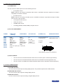
1-3. DEVICES & REFERENCES
REFERENCE
DESIGNATIONR
EFERENCEDESIGNATION
OXE831
OCTO VALUE.
1-4. INSTALLATION
IMPORTANT : Please read all the safety instructions page 3 before starting.
• Table Top Mounting : The device can be used directly on a table : the unit is equipped with 4 plastic feet.
• Rack Mounting :
The device is compatible with a 19” enclosure. To install the device into a 19” rack: Attach the device to the rack by using 4 screws in the front panel holes (screws are not included).
IMPORTANT :
PAGE 9
•The openings in the rear and side panels are for cooling. Do not cover these
openings.
•
Be sure that no weight is added to the device in excess of 2 kg (4.4 lbs.).
•
The maximum ambient operating temperature must not exceed 40°C (104°F).
•The rack and all mounted equipment in it must be reliably grounded to national
and local electrical codes.
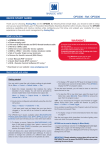
1-5 FRONT PANEL DESCRIPTION OF THE OCTO VALUE
INPUT #8 :
•
•
•
•
Universal (computer and video) input. This input accepts the following sources :
AUDIO L+R :
Audio stereo source on jack 3.5 female connector.
COMPUTER/TV/HDTV :Computer (RGBHV, RGBS or RGsB) or video (SDTV or HDTV) source on a HD15
female connector.
S.VIDEO :
S.VIDEO (Y/C) source on a 4-pin mini DIN female connector.
C.VIDEO :
Composite Video (PAL, NTSC...) source on a RCA female connector.
Fn : Secondary function selection button.
EFFECT PRESET :
Selection of the 6 EFFECT PRESET.
NOTE : Effect preset #4, 5 & 6 can be used by first pressing Fn.
FREEZE :
Freeze the main output (the blinking LED indicates the FREEZE is active).
LOGO : Allows to display logo onto the Main output.
NOTE :Logo display can be used by first pressing Fn.
INPUT SELECTION : • Selection of the 8 input sources : 1 to 8.
• Selection of the 4 frames : F1 to F4.
NOTE : - Frame selection can be used only when Fn is activate (LED blinking quickly).
-The pre-selected source (LED blinking slowly) is displayed onto the PREVIEW output.
-The pre-selected frame (LED blinking quickly) is displayed onto the PRE
VIEW output.
-The source/frame displayed onto the MAIN output is indicate by a turn ON LED.
• A long push (1 second) on the selected/preselected input button allows to active the
BLACK function. A black screen is displayed onto the corresponding output. A short
push on the same button allows to inactive this function.
TAKE :
Allows to display the pre-selected source onto the Main output with the selected effect.
CONTROL :
◄ ►
Allows to scroll thru the different menus (in Control mode).
EXIT – MENU :
Switches between Status and Control mode.
ENTER :
Validates a selected item.
PAGE 10
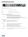
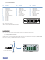
1-6. REAR PANEL DESCRIPTION OF THE OCTO VALUE
100-250 VAC, 1A, 50-60 Hz :
AC power inlet.
O / I :
AC power switch (O = OFF, I = ON).
IP/LAN :
LAN communication port on a RJ45 connector.
RS-232 :
RS-232 communication port on a DB9 female connector.
7 UNIVERSAL COMPUTER & TV/HDTV INPUTS :
1 :
Universal (computer and video) input on a DVI-I female connector.
NOTE : This input accepts analog & digital Computer source.
2 to 6 :
Universal (computer and video) inputs on a HD15 female connector.
7 :
Universal (computer and video) input on HD15 and 2 x BNC female connectors.
NOTE :All the universal inputs accept the following video source : Composite Video,
S-Video, SD-YUV, RGBHV, RGBS, RGsB & HD-YUV (HDTV)
DISPLAY OUTPUTS :
PREVIEW :
PREVIEW output on a HD15 female connector.
MAIN DVI :
MAIN digital & analog output on a DVI-I female connector.
MAIN ANALOG : MAIN analog output on a HD15 female connector.
AUDIO :
1 & 2 :
3 to 6 :
7 :
AUX :
OUT :
PRELIST :
Unbalanced stereo audio input #1 & #2 on 3.5 mm jack female connectors.
Unbalanced stereo audio input #3 to #6 on MCO male connectors.
Balanced stereo audio input #7 on a MCO male connector.
Balanced stereo auxiliary audio input on a MCO male connector.
Main stereo audio output (balanced & unbalanced) on a MCO male connector.
Prelist stereo audio output (unbalanced) on a MCO male connector.
Trigger +12 V :A room (+ 12 Vdc trigger) command (3.5 mm jack female), allows to control external functions
such as up/down screen, lighting...
PAGE 11
STARTING
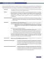
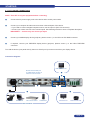
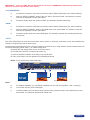
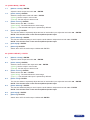
2-1. OCTO VALUE CONNECTIONS
NOTE :Turn OFF all of your equipment before connecting.
❶
Connect the AC power supply cord to the device and to an AC power outlet.
❷
Connect your computer & video sources to the 8 universal inputs of the device.
• If you need to connect a digital computer source, use the input #1 (DVI-I IN connector).
• Connect your others sources to the unused inputs. See following sections to have a complete description.
IMPORTANT : Connect only one source per input.
❸
Connect your MAIN display device (projector, plasma screen...) to the HD15 or DVI MAIN connector.
❹
If
required, connect your PREVIEW display device (projector, plasma screen...) to the HD15 PREVIEW
connector.
Turn ON the device (rear panel switch), then turn ON all your input sources and then your display device.
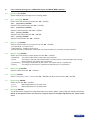
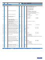
Connection diagram :
PREVIEW DISPLAY
RS-232 communication port
on a DB9 female connector or
TCP/IP on RJ45 connector
❹
❹
❷
❶
❸
❷
CAMERA
NOTEBOOK
VCR / DVD PLAYER
❸
COMPUTER
MAIN DISPLAY
MAIN PROJECTOR
INPUT SOURCES
PAGE 12
2-2. INPUT #1 DESCRIPTION
1) CONNECTION :
You can connect to this input one of the following sources :
• A composite video source.
• A S.video source.
• A Component video source.
• A HD-YUV source.
• A RGBS video source.
• An analog (RGBHV, RGsB, RGBS) computer source.
NOTE :You can use the DVI / HD15 adaptor provided with the device to connect analog sources
to the DVI-I (IN) connector.
• A digital computer source.
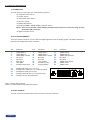
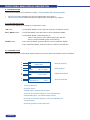
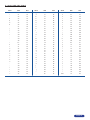
2) DVI-I PIN ASSIGNMENT :
The DVI-I female connector can be used with digital signals as well as analog signals. The table hereafter explains the pin assignment of this connector.
PinFunction PinFunction PinFunction
PinFunction
PinFunction
1
2
3
4
5
6
7
8
TMDS Data 2-
TMDS Data 2+
TMDS Data 2 Shield
Not used.
Not used.
DDC Clock
DDC Data
Analog Vertical Sync.
9
10
11
12
13
14
15
16
C1
C2
C3
C4
C5
Analog Red video (or Cr / Pr or C)
Analog Green Video (or Y or composite video)
Analog Bleu Video (or Cb / Pb)
Analog Horizontal Sync (or composite sync)
Analog Common Ground Return
TMDS Data 1-
TMDS Data 1+
TMDS Data 1 Shield
Not used.
Not used.
+ 5V (Power)
Ground for (+5V)
Hot plug detect.
PinFunction
17
18
19
20
21
22
23
24
TMDS Data 0TMDS Data 0+
TMDS Data 0 Shield
Not used.
Not used.
TMDS Clock Shield
TMDS Clock+
TMDS Clock-
1
9
C1 C2
16
17
DDC = Display Data Channel.
TMDS = Transition Minimized Differential Signal.
3) AUDIO SOURCE :
You can connect an AUDIO stereo source to the 3.5 mm jack connector.
PAGE 13
8
24 C3 C4
C5
2-3. INPUT #2 to 8 DESCRIPTION
1) CONNECTION :
You can connect to these inputs one of the following sources :
•
A composite source.
NOTE : Input #7 can accept a composite video source on the BNC connector. Input #8 can accept a
composite on the RCA connector.
• A S.video source.
NOTE : Input #7 can accept a S.video source on the BNC connectors. Input #8 can accept a S.video
source on the 4-pin mini DIN.
•
A Component video source.
•
A HD-YUV source.
•
A RGBS video source.
•
An analog (RGBHV, RGsB, RGBS) computer source.
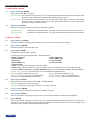
2) HD15 PIN ASSIGNMENT :
SIGNAL
SIGNAL
COMPUTER (analog) VIDEO RGB/S YUV & HD-YUV S.VIDEO (Y/C) COMPOSITE VIDEO
COMPUTER
VIDEO RGB/S
YUV & HD-YUV
S.VIDEO (Y/V)
COMPOSITE VIDEO
(analog)
PIN 1
PIN 2
PIN 3
PIN 6
PIN 7
PIN 8
PIN 10
PIN 13
PIN 14
RED.
RED.
Cr / Pr.C (chrominance).
GREEN.
GREEN.
Y.
Y (luminance).
VIDEO (NTSC, PAL...)
BLUE.
BLUE.
Cb / Pb.
RED return.
RED return.
Cr / Pr return.
C return.
GREEN return.
GREEN return. Y return.
Y return.
Return.
BLUE return.
BLUE return.
Cb / Pb return.
GND.
GND.
H sync or C sync (S). C sync (S).
1
5
10
V sync.
15
11
6
HD15 female connector of the device
3) AUDIO SOURCE
•
You can connect an unbalanced stereo audio source to the 3.5 jack connector (input #2 & 8).
•
You can connect an unbalanced stereo audio source to the MCO connector (input #3 to 6).
•
You can connect an unbalanced or balanced stereo audio source to the MCO connector (input #7).
2-4. OUTPUT DESCRIPTION
1) PREVIEW OUTPUT :
You can connect to this output an analog display device. The preview output format is XGA at 60 Hz.
2) MAIN ANALOG OUTPUT :
You can connect to this output an analog display device.
3) MAIN DVI OUTPUT :
You can connect to this output an analog or digital display device.
PAGE 14
4) DVI-I PIN ASSIGNMENT :
PinFunction PinFunction PinFunction
Pin
FunctionPin
FunctionPin
Function
1
2
3
4
5
6
7
8
C1
C2
C3
C4
C5
TMDS Data 2-
TMDS Data 2+
TMDS Data 2 Shield
Not used.
Not used.
DDC Clock
DDC Data
Analog Vertical Sync.
Not used
Not used
Not used
Not used
Not used
9
10
11
12
13
14
15
16
DDC = Display Data Channel.
TMDS = Transition Minimized Differential Signal.
17
18
19
20
21
22
23
24
TMDS Data 1-
TMDS Data 1+
TMDS Data 1 Shield
Not used.
Not used.
+ 5V (Power)
Ground for (+5V)
Hot plug detect.
1
9
TMDS Data 0TMDS Data 0+
TMDS Data 0 Shield
Not used.
Not used.
TMDS Clock Shield
TMDS Clock+
TMDS Clock-
8
C1 C2
C5
16
17
24 C3 C4
2-5. AUDIO INPUTS
Each audio input either has a 3.5 mm jack female connector or a 5-pin MCO male connector.
1) 3.5 mm jack female connector
The INPUTS # 1, 2, and 8 are equipped with this audio connector. This connector allows connecting only UNBALANCED
audio source. Connect your UNBALANCED audio sources as follow :
LEFT
(tip)
GROUND
3.5 mm JACK connector
RIGHT
(ring)
PAGE 15
2) MCO male connector
Input #3 to 7 & AUX are equipped with this connector. Connect your audio sources as follow :
- Input #3, 4, 5, & 6 : unbalanced connection only.
Input #3
LEFT
RIGHT
3
L
R
Input #4
GROUND(S)
LEFT
RIGHT
4
L
R
UNBALANCED
- Inputs #7 & AUX : balanced & unbalanced connection.
7
7
L+
L-
LEFT
GROUND
RIGHT
R+
R-
L+
L-
3
L+
L-
GROUND(S)
R+
R-
4
R+
R-
BALANCED
UNBALANCED
2-6. PRELIST AUDIO
You can connect an unbalanced stereo audio device to the 3.5 mm jack connector (for audio control).
2-7. AUDIO OUTPUT
The audio output is equipped with a 5-pin MCO male connector. This connector allows connecting BALANCED or
UNBALANCED audio systems.
OUT
OUT
LEFT
GROUND
RIGHT
UNBALANCED
L+
L-
L+
L-
L+
L-
R+
R-
GROUND(S)
R+
R-
R+
RBALANCED
PAGE 16
OPERATING MODE
The device can be used in two different switching modes :
•The SEAMLESS MODE, allows switching seamlessly, fading and titling between the “reference” COMPUTER
input and the other inputs. Other inputs are scaled to the same format as the “reference” COMPUTER format.
NOTE :Input #1 and #8 can be used as the reference capter input.
NOTE :The “reference” Computer is not scaled.
•The FAST SWITCHING MODE allows selecting an output format corresponding to your application. All video
inputs are scaled to the selected format. The switching between two inputs will go through a fade colored transition. The output rate can be selected between 60 Hz, 75 Hz or can be synchronized to one of the video input
frame rate in order to improve the motion picture. In this case, the output frame rate will be 50 Hz if the input is
in PAL or SECAM, and 59.94 Hz if the input is in NTSC.
3-1. SETTINGS
1)We recommend resetting the device to its default values, with the LCD menu (CONTROL > Default value > yes)
before proceeding.
2)Select a switching mode with the LCD menu (SWITCHING > fast switching or seamless). Please see the
Switching mode table below.
3)Select the Auto settings function with the LCD menu (INPUT > Auto settings). This function will detect automatically the source type connected to the inputs of the device. Sometimes, the auto setting may not detect the
source type : in this case select manually the source type with the LCD menu (INPUT > Input type).
4)If you have selected the fast switching mode : select one of the output formats with the LCD menu (OUTPUT >
output format).
NOTE :For fixed pixels display devices (DMD, LCD, PLASMA…), always select the output format corresponding to the native resolution of your device. Thus, the display device will not have to scale the image
and the result will be better.
NOTE :In SEAMLESS mode, the output format is the same as the “reference” computer format.
SWITCHING MODE TABLE
FAST SWITCHING
SWITCHING MODE
TRANSITION
OUTPUT FRAME RATE
internal rate
“input # x”
SEAMLESS
All switching through a All switching through a fade • Seamless or fade transition
fade color, a fade frame or color, a fade frame or a clean between the “reference” coma clean cut.
cut.
puter and all other inputs.
• Between "non reference"
inputs switching through a
fade color, a fade frame or a
clean cut.
Generated by the device Synchronized on the selected Synchronized on the “refe(60 Hz or 75 Hz).
input frame rate (50 Hz if PAL rence” Computer frame rate
or SECAM and 59.94 Hz if (input #1 or input #8).
NTSC).
3-2. SWITCHING OPERATIONS
• The device allows 4 different switching effects : CUT*, FADE*, FADE COLOR and CLEAN CUT. The CUT effect allows
switching seamlessly between 2 sources. The FADE effect allows fading out the displayed source while another source
is fading in. The FADE COLOR effect allows switching between 2 sources with a fading through the color of you choice.
The CLEAN CUT allows a clean switching thanks to a fast freeze of the displayed source.
• PIP* = Picture in Picture is also available effect.
• OXE831 also enables you to key text onto the displayed image (TITLE* effect).
!
PAGE 17
* The CUT, FADE, PIP and TITLE effects are active in SEAMLESS mode and only between the reference
computer input and the other inputs.
IMPORTANT : The CUT, FADE, PIP and TITLE effects are active in SEAMLESS mode and only between the
reference computer input and the other inputs.
• CUT (SEAMLESS) :
1)
Pre-select the reference computer input with the INPUT SELECTION button (The LED is blinking).
2)Select an EFFECT PRESET, assign it the CUT effect. Then press TAKE. The reference computer
input is then displayed onto the main output.
3)
Pre-select another input then press on TAKE. The transition operates seamlessly.
• FADE :
1)
Pre-select the reference computer input with the INPUT SELECTION button (The LED is blinking).
2)Select an EFFECT PRESET, assign it the FADE effect. Then press TAKE. The reference computer
input is then displayed onto the main output.
3)Pre-select another input then press TAKE again. The transition operates with a fading between the
two sources.
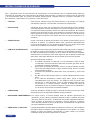
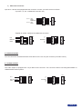
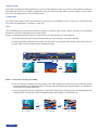
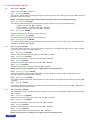
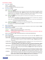
• TITLE :
The TITLE effect allows to insert text onto another source (video or computer). This effect is only active between the
reference computer input and the other inputs.
Create the text to be displayed on the computer used as the reference input, using software such as PowerPoint® : the
text should be bright (yellow, white...) on a black background.
a) Display the main background source on the main output.
b) Pre-select the reference computer input (input #1).
c) Select an EFFECT PRESET, then assign it the TITLE effect.
d) Then, press TAKE. The text appears onto the displayed image.
NOTE : To turn OFF the text, press TAKE again
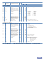
a)
b)
TITLE
Title source (Input #1)
c)
TITLE
Main source (Input #3)
Displayed image (MAIN)
NOTE :
a)
For a better readability, you can display a shadow bar onto your text (EFFECT > title > intensity).
b)To turn OFF the text, press TAKE again.
c)To switch between sources without turning OFF the text, press the button of the desired source and
press TAKE. The transition operates with a fade color.
PAGE 18
• FADE COLOR :
The FADE COLOR allows switching between 2 sources with a fading to a color of you choice. This transition operates in
Fast Switching mode and sometimes in Seamless mode (only when the other effects are not possible). You can select
the color of the fading with the LCD CONTROL menu.
• CLEAN CUT :
The CLEAN CUT allows a clean switch thanks to a fast freeze of the displayed source. Activate the CLEAN CUT with
the LCD menu (CONTROLS > transition > clean cut).
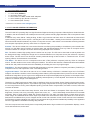
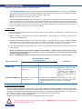
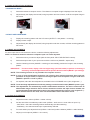
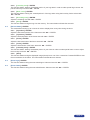
• PIP :
The PIP effect allows to insert a source onto the reference computer input or onto a frame. This effect is only possible
between the reference input/frame and the other inputs.
Display on the MAIN output the reference computer input or a frame (input #1 in this example).
a) Pre-select the input used for the PIP effect (input #3 in this example). The LED is blinking.
b) Select an EFFECT PRESET, then assign it the PIP effect. You can then adjust position and size of your PIP.
c) Press TAKE. The PIP appears onto the displayed image.
b)
c)
a)
TAKE
Reference input #1 (MAIN)
Displayed image (MAIN)
Input #3 (PREVIEW)
NOTE : To turn OFF the PIP, press TAKE.
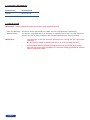
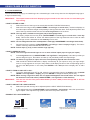
d) You can change the background image during a PIP effect (between the reference input & the frames store).
Press the reference input selection button or Fn button plus the desired frame selection button. The transition of
the background operates seamlessly.
e) You can change the PIP source (between the other inputs except for the reference input). Press the desired input
selection button. The transition of the PIP operates with a fade to black or a customized color.
d)
Frame #1 selection
Background = reference input #1
PIP = Input #3
PAGE 19
e)
Input #4 selection
Background = frame #1
PIP = Input #3
Background = frame #1
PIP = Input #4
3-3. DISPLAY DEVICE ADJUSTMENTS
• IN SEAMLESS MODE :
1)
Select the reference computer source. The reference computer image is displayed onto the output.
2)
djust directly the display device itself, using its position and size controls, to fill the computer image in
A
full screen.
❶
❷
• IN FAST SWITCHING MODE :
1)
Display the centering pattern with the LCD menu (OUTPUT > test pattern > centering).
2)
Display a black output.
3)
djust directly the display device itself, using its position and size controls, to fill the centering pattern in
A
full screen.
3-4. IMAGE ADJUSTMENTS
For each input source connected to the device, make the following adjustments:
NOTE :In seamless mode the reference computer input can not be adjusted.
1)
Select the source you want to adjust (with the front panel “INPUT SELECTION” buttons).
2)
Select the aspect ratio of your input source with the LCD menu (IMAGE > aspect ratio).
3)Use the Centering function (IMAGE > centering) to automatically position the image in the Centering
pattern.
IMPORTANT :
For best results, display a full size bright image (no black border) to perform a centering. If
necessary, correct the adjustment with the position & size functions (IMAGE > pos settings).
NOTE :The centering function is only available for computer sources.
NOTE :In case of same Input/Output resolution, the centering also achieves automatic pixel clock adjustments. It may be useful, to improve manually the pixel clock and phase using the LCD menu
(IMAGE > optimize > clock or phase).
4)
As required, make the other adjustments, available in the LCD IMAGE menu (color, brightness…).
NOTE :To set the image adjustments to the factory settings, use the Preset function (IMAGE > preset > yes).
NOTE :The adjustments are automatically stored in NON-volatile memories. The device comes with 40
NON-volatile image memories. Each of these memories contains the input channel number, the
input and output format parameters and all of the image adjustments (position, size, brightness...).
When the 40 memories are used, each new memorization erases the oldest record.
3-5. AUDIO ADJUSTMENTS
1)
Adjust the master volume (AUDIO > master volume).
2)
Set the auto follow or breakaway audio mode (AUDIO > audio source > auto follow or input # x):
- auto follow = the audio switching follows automatically the video switching.
- breakaway = the selected audio input is permanently diffused.
3)
For each audio input, adjust the level (AUDIO > audio level) and the balance (AUDIO > audio balance).
4)
Adjust your microphone (AUDIO > mic-control).
PAGE 20
USING FRAME & LOGO INSERTION
4-1. LOGO INSERTION
This function allows storing up to 8 static logos & 1 animated logo in order to key them into the displayed image (up to
2 logos simultaneously).
IMPORTANT : T
he output format used when displaying logos should be the same as the one used during the
logo storing.
• HOW TO STORE A LOGO :
1)
Select the source of the logo to be stored (with the INPUT SELECTION buttons).
2)Select the record logo mode (LOGOS/FRAME > record logo or record anim) : the device displays on
the main output a white rectangle corresponding to the logo selection area. Then adjust the position and
size of the logo selection area with the LCD record logo/anim menu functions.
NOTE :The logo area is limited to one eighth (1/8) of the displayed area.
3)If necessary, adjust the luma key level (LOGOS/FRAME > record logo or record anim > luma key
level). This function allows to “erase” the darkest portion of the logo selection area in order to make
special logo contour. Otherwise set the luma key level to zero.
NOTE : You can change the color of the “erased portion” of the logo (LOGOS/FRAME > record logo > back. Color).
4)Store the logo into a memory (LOGOS/FRAME > record logo > store > empty or logo x). The memorization of the logo starts and will take few seconds.
NOTE :Follow steps (1) to (4) to store another logo (up to 8).
• HOW TO ASSIGN A LOGO :
NOTE :You can assign the stored logos to one or more of the 8 inputs (up to 2 logos per inputs).
5)In the assignment menu (LOGOS/FRAME > use logo/frame > assignment), select the input that you
want to assign a logo to, then select an index (1 or 2) and finally select the required logo.
NOTE :To remove a logo from an input, select the corresponding input & index and select none.
6)With the INPUT SELECTION buttons, display successively all your inputs to verify your logo assignment. If no logo appears on an input: verify that the LCD display function of the corresponding input is
not set to the OFF position. In this case press ENTER to set it ON (see how to display OFF or ON a
logo).
• HOW TO TURN A LOGO OFF or ON :
7)To turn the assigned logos OFF or ON, select the corresponding input in the display menu (LOGOS/
FRAME > use logo/frame > display) and press ENTER to change the status (ON or OFF).
NOTE :When turning a logo ON or OFF, this one appears/disappears with a fade effect. You can adjust
the duration of this fade effect (LOGOS/FRAME > use logo/frame > fade duration).
IMPORTANT : You can also use the front panel LOGO button (Fn then LOGO) to turn the logo ON or OFF the
selected input.
• HOW TO ADJUST THE LOGO POSITION :
8)
Select the input with the logo to be adjusted (with the INPUT SELECTION buttons).
In the assignment menu (LOGOS/FRAME > use logo/frame > assignment), select the input and the
logo to adjust. Then adjust the logo position with the H &V position functions.
9)
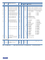
• EXAMPLE OF LOGO INSERTION :
Logo source
(white border = logo area)
PAGE 21
Video source
Video source with inserted logo
(logo recorded with luma key)
4-2. USING THE FRAME
This function allows memorizing up to 4 frames (images) in order to display them at any time during the show.
IMPORTANT :
The output format used when displaying the frame should be the same as the one used during
the FRAME storing.
• HOW TO STORE A FRAME :
1)
Select the source to be stored as a frame (with the INPUT SELECTION buttons).
2)Select the record frame mode (LOGOS/FRAME > record frame) : the device displays a white rectangle corresponding to the frame selection area onto the output. If necessary adjust the position and
size of the frame selection area (IMAGE > pos settings).
3)Store the frame (LOGOS/FRAME > record frame > store). The memorization starts and will take about
2 minutes.
NOTE :For motion picture, use the FREEZE function, before doing the memorization.
• HOW TO DISPLAY the FRAME ON or OFF :
4)To turn the FRAME ON, select a Frame selection button on the front panel (Fn then F1, F2, F3 or F4)
then press TAKE.
5)To turn the FRAME OFF, select an input selection button, then press TAKE.
PAGE 22
FRONT PANEL MENU DISPLAY DESCRIPTION
5-1. INTRODUCTION
The front panel display menu presents 2 modes : STATUS MODE and CONTROL MODE.
•
•
The STATUS MODE indicates the input and output status of the device.
The CONTROL MODE allows selecting and adjusting the parameters of the device.
5-2. CONTROL BUTTONS
The front panel display is controlled by 2 buttons and 1 knob :
◄► knob :
• In CONTROL MODE, turn this knob to scroll thru the different menus.
EXIT / MENU button : • In STATUS MODE, press this button to enter CONTROL MODE.
• In CONTROL MODE, press this button to :
- return to the previous menu without saving the selection.
- return to STATUS MODE (press several times).
ENTER button :
• From STATUS MODE, press this button to enter CONTROL MODE.
• From CONTROL MODE, press this button to confirm a selected item.
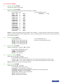
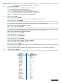
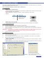
5-3. INTRODUCTION
When switching ON, the front panel display shows the product’s name and firmware version as follows :
1/
2/
OXE831
Version 242
3/
4/
MAIN : 1
XGA 60.1K / 75Hz
5/
6/
7/
8/
PREVIEW : 2
YUV 15.7K / 50Hz
Output : 1024x768
Seamless #1
75Hz
DEVICE STATUS
MAIN STATUS
PREVIEW STATUS
OUTPUT STATUS
1/ Device reference
2/ Device version
3/ MAIN output : selected input number
4/ Format, line & frame frequency to the selected input
5/ PREVIEW output : pre-selected input number
6/ Format, line & frame frequency of the pre-selected input
7/ Output format
8/ Switching mode & output frame rate
PAGE 23
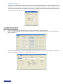
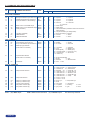
5-4. CONTROL MODE
1 SWITCHING
2 INPUT
1 Fast switching
Output rate
[ internal ]
[ follow #1 ]
...
[ follow #8 ]
2 Seamless
Seamless
[ seamless #1 ]
[ seamless #8 ]
1 Auto-setting
2 Input status
3 Input type
4 Used type
5 H. sync. load
6 VCR mode
7 VIS
3 OUTPUT
Output selection
Main Preview
1 #1 Comp. HV/C
2 #2 Comp. HV/C
3 #3 Comp. HV/C
4 #4 Comp. HV/C
5 #5 Comp. HV/C
6 #6 Comp. HV/C
7 #7 Comp. HV/C
8 #8 Comp. HV/C
9 All inputs
1 SDTV Composite
2 SDTV S.VIDEO
3 SDTV YUV
4 SDTV RGBS TTL
5 SDTV RGB SOG
6 SDTV RGBS ana.
7 Computer SOG
8 Computer HV/C
9 Computer DVI
1 NTSC/PAL/SECAM
2 NTSC
3 PAL
4 SECAM
5 B&w 50/60Hz
10 HDTV
11 Audio only.
1 Input #1 used
2 Input #2 unused
.............................
8 Input #8
used
1 Output status
2 Output format
3 Output rate
4 Output sync
1 852x480 16/9
2 800x600 4/3
3 1280x720p 16/9
4 1024x768 4/3
5 1280x768 16/9
6 1366x768 16/9
7 1280x1024 5/4
8 1400x1050 4/3
9 1920x1080 16/9
10 1600x1200 4/3
1 50 Hz
2 60 Hz
3 72 Hz
4 75 Hz
output sync
H&V COMP SOG
5 Type of screen
1 Screen 4/3
2 Screen 16/9
6 Test pattern
1 No pattern
2 Centering
3 Color bar
4 Grey scale
5 Grid
6 Burst
4 IMAGE
Image selection
Main Preview
1 Centering
2 Pos settings
1 H. position
2 V. position
3 H. size
4 V. size
3 Aspect in
1 4/3 standard
2 16/9 letterbox
3 WS anamorphic
4 Aspect out
1 Standard
2 Crop
3 Full screen
4 Zoom
IF VIDEO INPUT
5 Brightness
6 Contrast
7 Color
8 Hue
9 Under / Over
10 Preset
1 Zoom H. position
2 Zoom V. position
3 Zoom H. size
4 Zoom V. size
IF COMPUTER INPUT
5 Black level
6 Color
7 Optimise
8 Preset
1 Red level
2 Green level
3 Blue level
1 Clock
2 Phase
PAGE 24
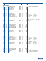
5 LOGO/FRAME
1 Use logo
1 Display
1 Input #1
....................
8 Input #8 OFF
2 Assignment
1 All inputs
2 Input #1
....................
Index 1 ► Logo 2
Index 2
None
1 None
2 Logo 1
3 Logo 2
4 Empty
....................
Index 1 ► Logo 2
Index 2
None
1 H. position
2 V. position
9 Input #8
3 Position
4 Transparency
5 Fade duration
Use logo
Main preview
1 Input #1
2 Input #2
...............
8 Input #8
2 Record logo
3 Record anim
4 Record frame
1 Size
2 Position
3 Luma Key level
4 Black color
5 Store
1 Logo 1 (L1)
................
8 Logo 8 (L8)
1 Size
2 Position
3 Luma Key level
4 Black color
5 Store
1 Frame 1 (F1)
................
8 Frame 8 (F8)
5 Erase logo
6 Erase frame
6 EFFECT
1 Key 1 : Cut
2 Key 2 : Fading
3 Key 3 : Title
4 Key 4 : Title
5 Key 5 : PIP
6 Key 6 : PIP
1 Cut
2 Fading
3 Title
3s
5s
Custom
1 Duration
2 Size
3 Position
4 Intensity
5 Effect opening
6 Effect closing
4 PIP
1 Duration
2 Image size
3 Image position
4 Window size
5 Window position
6 Effect opening
7 Effect closing
7 AUDIO MAIN
8 AUDIO PRELIST
1 Master volume
2 Audio mode
3 Audio source
4 Audio level
5 Audio balance
6 AUX input OFF
7 Mute
ON
PAGE 25
1 Mono
2 Stereo
1 Auto follow
2 Input #1
........
9 Input #8
Effect duration
========xxs
Holding
3s
5s
Custom
Cut
Fade in
Cut
Fade out
Opening duration
========xxs
Closing duration
========xxs
Holding
3s
5s
Custom
Cut
Fade in
Cut
Fade out
Opening duration
========xxs
Closing duration
========xxs
9 CONTROL
1 Versions
2 Transition
1 Red level
2 Green level
3 Blue level
1 Frame 1
------------4 Frame 4
1 Fade color
2 Clean cut
3 Fade frame
1 Black
2 Input #1
------------13 Input #4
3 Sync-loss
4 RS232 / LAN port
5 LAN setup
comm port select
RS232 LAN
1 Octo Value addr.
2 Remote addr.
3 Gateway addr.
4 Octo Value port
5 Remote port
1 UDP
2 TCP
6 Key locking
7 Stand-by
Fade duration
========xxs
1 All
2 Input
3 Menu
4 Auto lock
5 Auto take
6 Netmask
7 Default setup
select address
xxx.xxx.xxx.xxx
select port
xxxx
select netmask
xxx.xxx.xxx.xxx
1 Baud rate
2 Message ON
3 Message OFF
4 Reset message ON
5 Reset message OFF
6 Stand by time
7 Stand by
8 Erase memories
no
9 Default value
no
yes
yes
PAGE 26
5-5. FUNCTIONS DESCRIPTION
1►[SWITCHING] + ENTER.
1-1
1-2
[Fast switching] + ENTER.
Select an item with ◄► + ENTER.
• [Internal rate] :The output frame rate is 60 Hz or 75 Hz depending of the selected output format. A higher frame
frequency gives a better visual aspect when displaying static pictures.
• [Follow # x] : The output frame rate is identical to the selected input Frame Rate : 50 Hz if the input video
standard is PAL or SECAM and 59.94 Hz if the input video standard is NTSC. This function
allows improving the motion pictures.
[Seamless] + ENTER.
Select the computer input used as reference with ◄► + ENTER.
• [Seamless #1] :
The device is in Seamless mode. The output format & rate are the same as computer #1.
• [Seamless #8] :
The device is in Seamless mode. The output format & rate are the same as computer #8.
2►[INPUT] + ENTER.
2-1
[Auto settings] + ENTER.
This function detects automatically the input type of each source connected to the inputs.
2-2
[Input status] + ENTER.
Indicates the status of the selected input.
2-3
[Input type] + ENTER.
① Select an input with ◄► + ENTER.
② Select the input signal type with ◄► + ENTER between :
• [SDTV Composite]• [SDTV RGB SOG]
• [SDTV S.VIDEO]• [SDTV RGBS ana.]
• [SDTV YUV]• [Computer SOG]
• [SDTV RGBS TTL]• [Computer HV/C]
• [Computer DVI]
• [HDTV] : HDTV input format (720p, 1035i and 1080i).
• [Audio only] : Select this function if you only want to connect an audio source (no video signal needed).
③ Then for [SDTV Composite] and [SDTV S.VIDEO], select the video standard with ◄► + ENTER between :
• [NTSC / PAL / SECAM] : automatic NTSC, PAL, and SECAM standard detection.
• [NTSC] : NTSC standard detection only.
• [PAL] : PAL standard detection only.
• [NTSC 4.43 60 Hz] : NTSC 4.43 60Hz detection.
• [PAL 4.43 60Hz] : PAL 4.43 60Hz detection.
• [SECAM] : SECAM standard detection only.
• [B & W 50/60 Hz] : Black and White detection.
2-4
[used input] + ENTER.
Select an input and then select an item ◄► + ENTER between :
• [used] : A signal is connected to the input.
• [unused] : No signal is connected to the input. The input is unused.
2-5
[H sync load] + ENTER.
Select for each input the load of the H Sync. with ◄► + ENTER.
2-6
[VCR mode] + ENTER.
This function allows improving the image contour of low quality VHS tapes. Select [on] with ENTER.
2-7
[VIS] + ENTER.
This function allows defining the sources which are synchronized together (external genlock). The synchronized sources can be seamlessly switched between themselves during an effect (into a PIP for example). This
switching mode is called VIS (Vertical Interval Switching).
PAGE 27
3► [OUTPUT] + ENTER.
3-1[Output status] + ENTER.
Indicates the status of the output.
3-2[Output format] + ENTER.
Select one of the available output formats with ◄► + ENTER.
For the MAIN output :For the PREVIEW output :
• [852x 480 -----
16/9]• [1024x768 ---- 4/3]
• [800x 600 ----- 4/3]
• [1280x 720 -----
16/9]
• [1024x 768 ----- 4/3]
• [1280x 768 -----
16/9]
• [1280x 800 ----- 16/9]
• [1280x1024 ----- 4/3]
• [1366x 768 -----
16/9]
• [1400x1050 -----
4/3]
• [1440x 900 -----
16/9]
• [1600x1200 ----- 4/3]
• [1920x1080----- 16/9]
• [1920x1080B----- 16/9]
• [1920x1080HD-----
16/9]
• [1920x1200----- 16/9]
NOTE : For fixed pixels display devices (DMD, LCD, PLASMA…), always select the output format corresponding to the native resolution of the display device. Thus, the display device will not have to scale the image and
the result will be better.
3-3[Output rate] + ENTER.
For the MAIN output :
• [50 Hz] : 50 Hz output frame rate
• [60 Hz] : 60 Hz output frame rate
• [72 Hz] : 72 Hz output frame rate
• [75 Hz] : 75 Hz output frame rate
For the PREVIEW output :
• [60 Hz] : 60 Hz output frame rate
3-4[Output sync] + ENTER.
Select the Output Sync. type with ◄►+ ENTER.
For the MAIN & PREVIEW outputs :
• [H&V] : H & V Separate Sync.
• [COMP] : Composite Sync.
• [SOG] : Sync On green.
3-5[Type of screen] + ENTER.
Select an item with ◄► + ENTER.
For the MAIN & PREVIEW outputs :
• [screen 4/3] : If your image is displayed on a 4/3 wall mounted projection screen shape.
• [screen 16/9] : If your image is displayed on a 16/9 wall mounted projection screen shape.
NOTE :Available only in case of 4/3 output format.
3-6[Test pattern] + ENTER.
Select an item with ◄► + ENTER.
For the MAIN & PREVIEW outputs :
• [no pattern] : No test pattern is displayed.
• [centering] : Displays a centering pattern (for position and size adjustments).
• [color bar] : Displays a color bar pattern.
• [grey scale] : Displays a grey scale pattern.
• [grid] : Displays a grid pattern.
• [burst] : Displays a burst pattern.
PAGE 28
4►[IMAGE] + ENTER.
►
If the selected input type is a VIDEO signal the IMAGE MENU displays the following items :
4-1
[Pos. settings] + ENTER.
Select one of the following functions with ◄► + ENTER.
4-1-1 [H position] + ENTER.
Adjust the Horizontal position with ◄► + ENTER.
4-1-2 [V position] + ENTER.
Adjust the Vertical position with ◄► + ENTER.
4-1-3 [H size] + ENTER.
Adjust the Horizontal size with ◄► + ENTER.
4-1-4 [V size] + ENTER.
Adjust the Vertical size with ◄► + ENTER.
4-2
[Aspect in] + ENTER.
Select the Aspect Ratio of your input source with ◄► + ENTER.
• [4/3 standard] : 4/3 input format.
• [16/9 letterbox] : Letterbox input format.
• [WS anamorphic] : Widescreen Anamorphic input format (video) or 16/9 input format (computer).
4-3
[Aspect out] + ENTER.
Select one of the following output aspect ratio with ◄► + ENTER.
• [Standard] : The entire image and the aspect ratio are preserved.
• [Crop] :
The image is zoomed without deformation to fill the screen, but some borders of the image will
be cropped. The aspect ratio is preserved.
• [Full Screen] :The image is stretched to fill the screen. The aspect ratio is not preserved.
• [Zoom] :
The image can be zoomed, cropped and stretched at your convenience.
4-4
[Brightness] + ENTER.
Adjust the Brightness with ◄► + ENTER.
4-5
[Contrast] + ENTER.
Adjust the Contrast with ◄► + ENTER.
4-6
[Color] + ENTER.
Adjust the Color with ◄► + ENTER.
4-7
[Hue] + ENTER.
Adjust the Tint of the picture (NTSC only) with ◄► + ENTER.
4-8
[U/overscan] + ENTER.
Select Underscan or Overscan with ◄► + ENTER.
• [underscan] : Underscan mode. The entire image is visible on the screen. Computer mode is underscan.
• [overscan] :Overscan mode. The image is displayed about 8 % bigger than in underscan mode, to avoid
seeing the corners and the borders. Standard TV display mode is overscan.
4-9
[Preset] + ENTER.
This function allows setting all the image parameters to the factory settings. Select [YES] and validate with ENTER.
PAGE 29
►
If the selected input type is a COMPUTER signal the IMAGE MENU displays :
4-1
[Centering] + ENTER.
Adjust automatically the image in the centering pattern.
4-2
[Pos. settings] + ENTER.
Select one of the following functions with ◄► + ENTER.
4-2-1 [H position] + ENTER.
Adjust the Horizontal position with ◄► + ENTER.
4-2-2 [V position] + ENTER.
Adjust the Vertical position with ◄► + ENTER.
4-2-3 [H size] + ENTER.
Adjust the Horizontal size with ◄► + ENTER.
4-2-4 [V size] + ENTER.
Adjust the Vertical size with ◄► + ENTER.
4-3
[Aspect in] + ENTER.
Select the Aspect Ratio of your input source with ◄► + ENTER.
• [4/3 standard] : 4/3 input format.
• [16/9 letterbox] : Letterbox input format.
• [WS anamorphic] : Widescreen Anamorphic input format (video) or 16/9 input format (computer).
4-4
[Aspect out] + ENTER.
Select one of the following output aspect ratio with ◄► + ENTER.
• [Standard] : The entire image and the aspect ratio are preserved.
• [Crop] :
The image is zoomed without deformation to fill the screen, but some borders of the image
will be cropped. The aspect ratio is preserved.
• [Full Screen] : The image is stretched to fill the screen. The aspect ratio is not preserved.
• [Zoom] :
The image can be zoomed, cropped and stretched at your convenience.
4-5
[Black level] + ENTER.
Adjust the black level with ◄► + ENTER.
4-6
[Color] + ENTER.
Select a color (Red, Green, or Blue) with ◄► + ENTER and adjust the level with ◄► + ENTER.
4-7
[Optimize] + ENTER.
Select an item with ◄► + ENTER.
• [clock] :
Manual adjustment of the pixel clock.
• [phase] :
Manual adjustment of the pixel phase.
4-8
[Preset] + ENTER.
This function allows setting all the image parameters to the factory settings. Select [YES] and validate with ENTER.
NOTE :If the selected input is the reference computer input, the available adjustments are : Black level &
Color.
PAGE 30
5► [LOGOS/FRAME] + ENTER
5-1
[Use logo] + ENTER.
Select an item with ◄► + ENTER.
5-1-1[Display] + ENTER.
This function allows turning the assigned logos of each input ON or OFF. Select an input with ◄► and press
ENTER to select ON or OFF.
NOTE :To display a logo the output format should be the same as the one used during the storing.
5-1-2[Assignment] + ENTER.
This function allows assigning the stored logos to an input device (up to 2 logos simultaneously).
① Select an input with ◄► + ENTER.
② Select INDEX 1 or INDEX 2 with ◄► + ENTER.
③ Then select a logo or none with ◄► + ENTER.
5-1-3[Position] + ENTER.
Adjust the logo position with H & V position functions.
5-1-4[Transparency] + ENTER.
This function allows adjusting the logo transparency.
5-1-5[Fade duration] + ENTER.
This function allows adjusting the fade duration of the logo when you turn ON or OFF a logo. Adjust the duration
with ◄► and validate with ENTER.
5-2
[Record logo] + ENTER.
This mode allows storing up to 8 logos in order to key them on the displayed image (up to 2 logos simultaneously). Select an item with ◄► + ENTER.
5-2-1[H position] + ENTER.
Adjust the Horizontal position of the logo area with ◄► + ENTER.
5-2-2[V position] + ENTER.
Adjust the Vertical position of the logo area with ◄► + ENTER.
5-2-3[H size] + ENTER.
Adjust the Horizontal size of the logo area with ◄► + ENTER.
5-2-4[V size] + ENTER.
Adjust the Vertical size of the logo area with ◄► + ENTER.
NOTE :The logo area is limited to one eighth (1/8) of the displayed area.
5-2-5[Luma key level] + ENTER.
This function allows “erasing” the darkest portion of your logo area in order to make special logo contour. Adjust the luma key level with ◄► + ENTER.
5-2-6[Back. Color] + ENTER.
This function allows coloring the “erased portions” of the logo when using the luma key. Select a level with ◄►
+ ENTER.
5-2-7[Store] + ENTER.
This function allows storing the logo into one of the 8 memories. Select a logo memory with ◄► + ENTER. The
memorization will take few seconds.
5-3
[Record anim] + ENTER.
This mode allows storing an animated logo in order to key them into the displayed image. Select an item with
◄► + ENTER.
5-3-1[H position] + ENTER.
Adjust the Horizontal position of the logo area with ◄► + ENTER.
5-3-2[V position] + ENTER.
Adjust the Vertical position of the logo area with ◄► + ENTER.
5-3-3[H size] + ENTER.
Adjust the Horizontal size of the logo area with ◄► + ENTER.
5-3-4[V size] + ENTER.
Adjust the Vertical size of the logo area with ◄► + ENTER.
NOTE :The logo area is limited to one eighth (1/8) of the displayed area.
PAGE 31
5-3-5 [Luma key level] + ENTER.
This function allows “erasing” the darkest portion of your logo area in order to make special logo contour. Adjust the luma key level with ◄► + ENTER.
5-3-6[Back. Color] + ENTER.
This function allows coloring the “erased portions” of the logo when using the luma key. Select a level with
◄►+ ENTER.
5-3-7[Recording time] + ENTER.
Adjust the recording time with ◄► + ENTER.
5-3-8[Store] + ENTER.
This function allows storing the logo into the memory. The memorization will take few seconds.
5-4
[Record frame] + ENTER.
This mode allows storing up to 4 frames in order to display them at any time during the show.
5-4-1 [H position] + ENTER.
Adjust the Horizontal position of the frame area with ◄► + ENTER.
5-4-2 [V position] + ENTER.
Adjust the Vertical position of the frame area with ◄► + ENTER.
5-4-3 [H size] + ENTER.
Adjust the Horizontal size of the frame area with ◄► + ENTER.
5-4-4 [V size] + ENTER.
Adjust the Vertical size of the frame area with ◄► + ENTER.
5-4-5 [Luma key level] + ENTER.
This function allows “erasing” the darkest portion of your frame in order to make special frame contour. Adjust
the luma key level with ◄► + ENTER.
5-4-6[Store]
This function allows storing the displayed image (frame) into a one of the 4 memories. Presses ENTER to start
the memorization of the frame. The memorization will take about 2 minutes.
5-5
[Erase logo] + ENTER.
This function allows erasing the memorized logos. Select an item with ◄► + ENTER.
5-6
[Erase frame] + ENTER.
This function allows erasing the memorized frames. Select an item with ◄► + ENTER.
PAGE 32
6►[EFFECT]
This menu allows storing an effect in each of the effect buttons (EFFECT PRESET).
① First select an effect button with LCD menu or with the front panel button.
② Then select one of the following effects:
6-x-1 [Cut] : allows switching seamlessly the pre-selected input onto the MAIN output.
6-x-2 [Fading] : allows fading the pre-selected input to the MAIN output. You can select the duration of the
transition as indicated below :
• [1s] : 1 second transition.
• [3s] : 3 second transition.
• [5s] : 5 second transition.
• [Custom] : Select a duration from 0.5 second up to 25 seconds by 0.5 second steps.
6-x-3 [Title] : Allows overlaying a title on the MAIN output. The title should be created using software such
as PowerPoint : the text should be bright (yellow, white) on a black background. A shadow bar is also
available for increasing the readability of the text on bright images
①
Select the [duration] of the transition with ◄► + ENTER between :
• [holding] : The text appears after pushing on the TAKE button, and will be removed only by a second
push on the TAKE button.
• [3s] : 3 second transition.
• [5s] : 5 second transition.
• [custom] : Select a duration from 0.5 second up to 25 seconds by 0.5 second steps.
②
Select the [Size] of the shadow bar with ◄► + ENTER.
③
Select the vertical [Position] of the shadow bar with ◄► + ENTER.
④
Select the [Intensity] of the shadow with ◄► + ENTER.
⑤
Select the [Effect opening] and the [effect closing] of the title between [Cut] & [Fade] with ◄► + ENTER.
6-x-4 [PIP] : Allows displaying a picture into another picture. The PREVIEW image is reduced and displayed
onto the MAIN image.
①
Select the [duration] of the transition, and validate with ENTER.
• [holding] : The PREVIEW image appears after pressing on the TAKE button, and will be removed only
by a second push on the TAKE button.
• [3s] : 3 second transition.
• [5s] : 5 second transition.
• [custom] : Select a duration from 0.5 second up to 25 seconds by 0.5 second steps.
②
Adjust the [Image size] of the PIP with H and V, and validate with ENTER.
③Set the horizontal and vertical [Image position] of the PIP with the H and V knob, and validate with
ENTER.
④Adjust the [Window size] of the PIP with the H and V knob, and validate with ENTER. This function
allows, for example, cutting the black bars of a letterbox source.
⑤
Adjust the [Window position] of the PIP with the H and V knob, and validate with ENTER.
⑥Select the [Effect opening] and the [effect closing] of the PIP between [Cut] & [Fade] with ◄►
+ ENTER.
PAGE 33
7► [AUDIO MAIN] + ENTER.
7-1
[Master volume] + ENTER.
Adjust the audio output level with ◄► + ENTER.
7-2
[Audio mode] + ENTER.
Select the output audio mode with ◄► + ENTER.
• [Mono] : Set the output in mono mode.
• [Stereo] : Set the output in stereo mode.
7-3
[Audio source] + ENTER.
Select an item with ◄► + ENTER :
• [auto follow] : The audio follows the video image.
• [input --] : The selected audio input is permanently diffused.
7-4
[Audio level] + ENTER.
This function allows to separately adjust the level of each audio input. Adjust the level with ◄► + ENTER.
NOTE :This function acts on the selected (diffused) audio input.
7-5
[Audio balance] + ENTER.
This function allows adjusting for each input the audio balance. Adjust the level with ◄► + ENTER.
NOTE :This function acts on the selected (diffused) audio input.
7-6
[AUX input] + ENTER.
7-7
[Mute off] + ENTER.
Switch ON or OFF the audio output. Validate with ENTER.
8► [AUDIO PRELIST] + ENTER.
8-1
[Master volume] + ENTER.
Adjust the audio output level with ◄► + ENTER.
8-2
[Audio mode] + ENTER.
Select the audio mode of the output with ◄► + ENTER.
• [Mono] : Set the output in mono mode.
• [Stereo] : Set the output in stereo mode.
8-3
[Audio source] + ENTER.
Select an item with ◄► + ENTER:
• [auto follow] : The audio follows the video image.
• [input --] : The selected audio input is permanently diffused.
8-4
[Audio level] + ENTER.
This function allows to separately adjust the level of each audio input. Adjust the level with ◄► + ENTER.
NOTE :This function acts on the selected (diffused) audio input.
8-5
[Audio balance] + ENTER.
This function allows adjusting for each input the audio balance. Adjust the level with ◄► + ENTER.
NOTE :This function acts on the selected (diffused) audio input.
8-6
[AUX input] + ENTER.
8-7
[Mute off] + ENTER.
Switch ON or OFF the audio output. Validate with ENTER.
PAGE 34
9►[CONTROL] + ENTER.
9-1
[Versions] + ENTER.
Version _._= update version.
I1 to I4 = Identification number.
K, A, B, C, O = status of the internal firmware versions.
9-2
[Transition] + ENTER.
Select an item with ◄► + ENTER
9-2-1 [Fade color] + ENTER.
This function allows selecting the color of the frame during the fade through frame transition. Select
a color (red, green and blue) with ◄► + ENTER and adjust the level with ◄► + ENTER. During the
adjustment the color is displayed on the output. To obtain black, set the 3 levels to minimum. To obtain
white, set the 3 levels to maximum. To obtain grey, set the 3 levels in the middle.
9-2-2 [Clean cut] + ENTER.
This function allows a clean switching thanks to a fast freeze of the displayed source. Select a function
with ◄► + ENTER.
• [from computer] : The CLEAN CUT operates only when switching from a computer source. Switching
from other sources operates with a fade color.
• [from video] : The CLEAN CUT operates only when switching from a video source. Switching from
other sources operates with a fade color.
• [from all] : The CLEAN CUT operates when switching from any source.
9-2-3 [Fade frame] + ENTER.
This function allows switching by a fading through a frame (instead of a color). Select a frame and adjust
the duration of the transition with ◄► + ENTER.
9-3
[Sync loss] + ENTER.
Allows to display a frame or a source in case of sync-loss of the selected input. Select an items with ◄► + ENTER
9-4
[RS232/LAN port] + ENTER.
Select the communication port with ◄► + ENTER.
• [RS232] :
Enables the RS-232 communication port. (Default setting).
• [LAN] :
Enables the LAN communication port.
IMPORTANT :To avoid address conflicts, configure the LAN communication port (with the LAN setup
menu) before activating it.
NOTE :The RS-232 & the LAN communication ports can not be used simultaneously.
9-5
[LAN setup] + ENTER.
Allows configuring the LAN communication port. Select the UDP or TCP protocol with ◄► + ENTER then select
items with ◄► + ENTER.
• [device addr.] : Every device connected to an IP network must have a unique IP address. This address is used
to reference the specific unit. IP addresses are specified as x.x.x.x where each x is a number
from 1 to 254. Assign the device to a unique IP address with ◄► + ENTER. (Default value:
192.168.0.2).
• [remote addr.] : T
his is the destination IP address used with an outgoing connection. Select the destination IP
address with ◄► + ENTER. (Default value : 192.168.0.1).
• [gateway addr.] : The gateway address, or router, allows communication with other LAN segments. The gateway address should be the IP address of the router connected to the same LAN segment
as the unit. Select the gateway address with ◄► + ENTER. (Default value : 192.168.0.1).
• [device port] : Every TCP connection and every UDP datagram is defined by a destination IP address and a
port number. Select a local port number with ◄► + ENTER between 10000 and 10999. (Default value : 10500).
• [remote port] :You must set the remote TCP port number for the unit to make outgoing connections. This parameter defines the port number on the target host to which a connection is attempted. Select
a remote port number with ◄► + ENTER between 00000 and 655000. (Default value : 10500).
• [netmask] : A netmask defines the number of bits taken from the IP address that are assigned for the host
section. The device prompts for the number of host bits to be entered, then calculates the
netmask, which displays in standard decimal-dot notation when the saved parameters are displayed. Select the netmask with ◄► + ENTER. (Default value : 255.255.255.0).
• [default setup] : S
et all the LAN settings to default value. Select [YES] and validate with ENTER.
PAGE 35
MAC address : The MAC address, also referred to hardware address, is a unique number assigned to each device.
The MAC address is available on the bottom device label.
9-6
[key locking] + ENTER.
Select an item with ◄► and change the mode with ENTER.
• [All] : Locks/unlocks all the front panel switches.
• [Menus] : Locks/unlocks the LCD CONTROL switches.
• [autolock] : Allows selecting an input only if a signal is connected.
• [Input] : Locks/unlocks the INPUT SELECTION and FREEZE switches.
NOTE : To unlock press simultaneously ENTER and EXIT.
9-7[Stand-by] + ENTER.
9-7-1[Baud rate] + ENTER.
Select the baud rate of the display device with ◄► + ENTER (9600, 2400 & 1200).
9-7-2[Message ON] + ENTER.
This function allows to store the ON message of your display device. Whenever your device goes out of standby mode it will send the stored message to your display device. The ON message can be composed of up to 50
bytes. For each byte, select the required ASCII code with ◄► and validate with ENTER.
NOTE : The 0 value allows to display : no data.
9-7-3[Message OFF] + ENTER.
This function allows to store the OFF message of your display device. Whenever your device goes out of standby mode it will send the stored message to your display device. The OFF message can be composed of up to
50 bytes. For each byte, select the needed ASCII code with ◄►, then press ENTER.
NOTE : The 0 value allows to display: no data.
9-7-4[Reset mess ON] + ENTER.
Allows to reset the ON message.
9-7-5[Reset mess OFF] + ENTER.
Allows to reset the OFF message.
9-7-6[Stand by time] + ENTER.
When the device doesn't detect any signal on the selected input, it sets itself to STANDBY mode after the duration of your choice. Select a duration with ◄► + ENTER.
NOTE : Select OFF to inactivate this function.
9-7-7[Stand by] + ENTER.
Allows to set the device to STANDBY mode. To get out of STANDBY mode, press one of the front panel buttons.
9-8
[Erase memories] + ENTER.
This function allows erasing all NON-volatile image memories. Select [YES] and validate with ENTER.
9-9
[Default value] + ENTER.
This function allows setting the following functions to the factory settings. Select [YES] and validate with ENTER.
FUNCTIONPOSITION
input type
Computer HV/C.
used input
All used.
H sync load
All Hi-Z.
VCR mode
All off
output format
SXGA 60Hz 4/3.
Output sync
H&V.
type of screen
4/3
test patternno
switchingseamless #1
pos. settings
0
aspect ratio in
4/3
aspect ratio out
1:1
brightness128
black level128
contrast128
color128
hue128
under/overscan
overscan
sharpness3
master volume
192
audio source
auto follow
audio level48
audio balance
32
auxiliary input
OFF
muteOFF
display logo
all ON
assignmentall none
key locking
all unlock
fade color R, G, B = 0
RS232/LAN port
RS232
PAGE 36
UPDATING THE DEVICE
6-1. INTRODUCTION
The device can be updated thanks via RS232 communication port or via LAN communication port of a computer (PC).
6-2. CONNECTION
1)
Connect the device to an AC power outlet.
2)
Switch ON the device (REAR PANEL SWITCH = I).
3)
Connect the device to the computer used for the update via the desired communication port.
- For the RS232 communication port : Connect the RS232 connector of the device to the serial port of your
computer with a DB9 M/F straight cable.
- For the LAN communication port : Connect the RJ45 connector of the device to your network according to
your installation. Then with the front panel display menu configure the LAN communication port (CONTROL >
LAN setup) and activate the LAN communication port (CONTROL > RS232/LAN port > LAN).
6-3. UPDATE INSTRUCTIONS
1)
Switch ON the device.
2)
Open the file : Octo Value Updater (in Start > Program > ANALOGWAY > Octo Value Updater).
3)
Click on the Port menu and select setup : the Communication setup window open.
- If you use the RS232 port : Select RS232 and the Com port connected to the device.
- If you use the LAN Port : Select UDP or TCP and select the communication parameters.
4)
Click on START on the software. The update will start.
5)When the software displays : Program operation completed, click on the Quit button to close the update
software. Your device is now ready to work.
NOTE :
PAGE 37
The updater files are available on our web site : http://www.analogway.com
REMOTE CONTROL SOFTWARE
Your device is shipped with a Windows compatible Remote Control Software. This software allows you to control and
make all adjustments by a simple mouse click.
NOTE :Preferably use Windows NT, 2000 or XP for LAN operation.
7-1. CONNECTIONS
CONNECTING TO THE RS232 PORT :
- Connect the serial port of your control device to the RS232 port (DB9 Female connector) of the device with a
straight cable (DB9 Female / DB9 Male).
- Speed transmission : 9600 bauds, 8 data bits, 1 stop bit, no parity bit, no flow control.
- Pin-out :
①
PIN #
FUNCTIONS
2
3
5
TRANSMIT DATA (Tx)
RECEIVE DATA (Rx)
GROUND (Gnd)
②
DB9 female (Rear
panel of the device)
CONNECTING TO THE LAN PORT :
- Connect the LAN port (RJ45 connector) of the device to your network according to your installation.
7-2. SOFTWARE INSTALLATION
Turn your computer ON and wait for Windows to completely start.
Insert the CD-ROM into your drive : the ANALOG WAY home window will open automatically.
Select the language of the CD-ROM menus, then click on “Install a Remote Control Software” and select the
name of your device.
IMPORTANT :If the Autorun is not enabled : From the Windows desktop, open My Computer and select the
CD-ROM drive. Select the Autorun folder, and then select the autorun.exe file.
④
Follow the Windows installation instructions.
①
②
③
7-3. COMMUNICATION SETUP
①
Connect the RS232 or RJ45 cable between the device and the control device as indicated in the section 7-1.
②
Then power ON all of the devices.
③
Click on the program files Octo Value in Start > program > ANALOGWAY > Octo Value to run the software.
④
Click on Control menu and select RS232/LAN setup, then :
• CASE OF RS232 PORT :
- With the front panel display menu of the device, verify that the RS232 port is activated (CONTROL > RS232/
LAN port > RS232).
- With the Control menu of the software, select RS232/LAN setup, then select RS232 and select the COM port
number corresponding to the connection of the device in the Port field.
If the communication is OK, the message
"Device connected" is displayed as well as the
model in the windows title bar.
PAGE 38
• CASE OF LAN PORT :
- With the front panel display menu of the device, verify the configuration of the LAN communication port
(CONTROL > LAN setup), then activate the LAN communication port (CONTROL > RS232/LAN port > LAN).
- With the Control menu of the software, select RS232/LAN setup and LAN Setup. Then configure the Local
port, the Remote IP address and the Remote port and click on Apply to setup the new values. The software will
also display Device connected.
7-4. USING THE SOFTWARE
①
Click on the Settings button (left bottom of the window) to display the Settings window.
②Click on the Input Settings tab and select the Signal Type for each input. Then make the other adjustments
(video Standard...).
③Click on the Output tab, then select the Switching mode (internal rate, input #- rate, or seamless), then select
the desired adjustment (output sync, output format, output rate...).
PAGE 39
④
Click on the Image tab and adjust your input.
⑤
lick on the Audio tab and select Automatic (follow switching mode) or an Audio source (breakaway mode).
C
Then adjust the Level and the Balance of each audio source.
7-5. Frames and Logos Loader
The RCS provides additional functionality. It can download logos, animated logo or frames via the RS-232 or
Ethernet (LAN). This feature also allows downloading a logo animated in GIF format.
To dowload logos, it is recommended not to exceed 1/8th of the final size of the output image Main.
Supported formats are : JPEG, BMP, GIF, JPG, ICO, EMF, WMF.
PAGE 40
TECHNICAL SPECIFICATIONS
8-1. COMPUTER & VIDEO INPUTS
• ANALOG COMPUTER
Connectors :
HD15 (inputs #2 to 8) and DVI-I (input #1).
Line frequency :
Up to 110 kHz.
Frame frequency : Up to 130 Hz.
Resolution : Up to 1600 x 1200/60Hz.
Sync. types :
RGBHV, RGB/S, RGsB (Sync On Green).
Levels :
R, G, B = 0.7 Vp/p.
H & V Sync = TTL
Composite Sync = TTL and 0.3 V.
SOG (Sync On Green) = 0.3 V.
Impedance :
R, G, B = 75 ohms.
H = 75 Ohms or Hi-Z.
V = Hi-Z.
• DIGITAL COMPUTER INPUT
Connectors :
DVI-I (input #1).
Format :
Digital Visual Interface (DVI)
TMDS single link.
Resolution : Up to 1600 x 1200/60Hz RB (reduced blanking) and 1920x1080/60Hz.
• RGB/S VIDEO
Connectors :
HD15 (inputs #2 to 8) and DVI-I (input #1).
Frequency :
15.625 kHz / 50 Hz (625 lines).
15.734 kHz / 60 Hz (525 lines).
Levels :
R, G, B = 0.7 Vp/p.
SYNC. = 0.3 Vp/p or TTL.
Impedance :
RGB = 75 ohms.
SYNC. = 75 Ohms or Hi-Z.
• COMPONENT
Connectors :
Frequency :
Levels :
Impedance :
HD15 (inputs #2 to 8) and DVI-I (input #1).
15.625 kHz / 50 Hz (625 lines).
15.734 kHz / 60 Hz (525 lines).
Y = 1 Vp/p (0.7 V Luma + 0.3 V Sync.).
R-Y = 0.7 Vp/p.
B-Y = 0.7 Vp/p.
Y, R-Y, B-Y = 75 Ohms.
• HDTV
Connectors :
Formats : Levels :
Sync. : Impedance :
HD15 (inputs #2 to 8) and DVI-I (input #1).
HD-YUV (1080i/60-50Hz, 1080p, 720p/60-50Hz, 480p/60Hz).
Y = 1 Vp/p (0.7 V + sync.).
R-Y = 1 Vp/p (0.7 V + sync.).
B-Y = 1 Vp/p (0.7 V + sync.).
Tri-level: ±0.3V (positive/negative).
Bi-level: 0.3V (negative).
75 Ohms.
• S.VIDEO
Connectors :
Standards :
Levels :
Impedance:
4-pin mini DIN (input #8), BNC (input #7), HD15 (inputs #2 to 8) and DVI-I (input #1).
PAL (15.625 kHz / 50 Hz – 625 lines) or NTSC (15.734 kHz / 60 Hz – 525 lines).
Y = 1 Vp/p.
C = 0.3 Vp/p.
75 Ohms.
• COMPOSITE VIDEO
Connectors :
Standards :
Level :
Impedance :
BNC (input #7), RCA (input #8), HD15 (inputs #2 to 8) and DVI-I (input #1).
PAL / SECAM (15.625 kHz / 50 Hz – 625 lines) or NTSC (15.734 kHz / 60 Hz – 525 lines).
1 Vp/p.
75 Ohms.
PAGE 41
8-2. DISPLAY OUTPUTS
• MAIN ANALOG
Connectors :
Resolution : Frame frequency :
Sync. types :
Levels :
Impedance :
HD15 and DVI-I (2x buffered).
4/3 & 5/4 : 800x600, 1024x768, 1280x1024, 1400x1050, 1600x1200.
16/9 & 16/10 : 852x480, 1280x720, 1280x768, 1366x768, 1920x1080.
50, 60, 72***, 75*** Hz and follow (*** = not available for all resolutions).
RGBHV, RGB/S, RGsB (Sync On Green).
R, G, B = 0.7 Vp/p.
H & V Sync = TTL
Composite Sync = TTL and 0.3 V.
SOG (Sync On Green) = 0.3 V.
R, G, B = 75 ohms.
• MAIN DIGITAL
Connector :
Format :
Resolution : DVI-I.
Digital Visual Interface (DVI). TMDS Single link.
Up to 1600 x 1200 @ 60 Hz.
• PREVIEW
Connectors :
Format : Sync. types :
Levels :
Impedance :
HD15.
XGA / 60 Hz.
RGBHV.
R, G, B = 0.7 Vp/p.
H & V Sync = TTL
R, G, B = 75 ohms.
8-3. AUDIO INPUTS
Connectors :
Jack 3.5 mm (inputs #1, 2 & 8) and MCO (inputs #3, 4, 5, 6, 7 & AUX).
Type :
Stereo balanced (inputs 7 & AUX) & unbalanced.
Levels :
Vi = + 18 dBu (max).
Zi = 20 kΩ unbalanced.
Zi = 40 kΩ balanced.
Gain :Adjustable.
8-4. MAIN AUDIO OUTPUT
Connectors :
Type :
Levels :
Gain : MCO.
Stereo balanced & unbalanced.
Vo = + 18 dBu max (unbalanced).
Zo = 300 Ω (unbalanced).
Vo = + 24 dBu max (balanced).
Zo = 600 Ω (balanced).
0 dB nominal (adjustable with Master volume).
8-5. PRELIST AUDIO OUTPUT
Connectors :
Jack 3.5 mm.
Type :Unbalanced.
Levels :
Vo = + 18 dBu max.
Zo = 300 Ω.
Gain : 0 dB nominal (adjustable with Master volume).
PAGE 42
8-6. COMMUNICATION PORTS
• RS232 (on DB9 female connector)
Data Rate :
9600 Bauds, 8 data bits, 1 stop bit, no parity bit, no flow control.
Pin-out :
PIN #
2
3
4
5
8
9
• LAN
Protocol :
Data Rate :
FUNCTIONS
Tx1 (transmit data to the control device)
Rx1 (receive data from the control device)
Rx2 (receive data from the display device)
GROUND (Gnd)
Reserved for manufacturer.
Tx2 (transmit data to the display device)
TCP (Transmission Control Protocol) / UDP (User Datagram Protocol).
10 / 100 Mbps.
LED functions (on RJ45 connector) :
Left LED
Right LED
Meaning
OFF OFFNo link
OFF ON 100 BASE-T link.
ON OFF 10 BASE-T link.
8-7. TRIGGER
Connector :
Command levels :
Output Current :
Jack 3.5 mm female.
ON = + 12 Vdc trigger. OFF = 0 Vdc.
0.1 A max at + 12 Vdc.
Jack 3.5 connection
NOTE : This output is activate with the AC Power Switch (ON/OFF).
+ 12 Vdc
Ground
8-8. ENVIRONMENTAL
Power Supply : Storage Temperature : Operating temperature :
Hygrometry : Dimensions : Weight :
PAGE 43
Internal CE / UL / CSA / IEC 950 (50 W), universal, automatic.
Input : 100 VAC to 250 VAC; 50-60 Hz; I = 1 A Max.
- 40 °C to + 70 °C (- 40 °F to + 158 °F).
0 °C to + 50 °C (32 °F to 122 °F).
10% to 80% (without condensation).
D 265 x W 482 x H 44 mm / D 10.4” x W 19” x H 1.74”.
Compatible with the 19” rack (height = 1 unit).
3.5 kg / 7.7 lbs.
APPENDIX : PROGRAMMER’S GUIDE
A. INTRODUCTION
If you need to use your own Software Control program from a PC or WORKSTATION with an RS232 port, the device
allows communication through an ASCII code protocol.
The device treats any character that it receives on the RS-232 as a possible command but only accepts legal commands. There is no starting/ending code needed in a command string.
A command can be a single character typed on a keyboard and does not require any special character before or after
it. (It is not necessary to press "ENTER" on the keyboard). A command can be preceded by a value (See chapter B).
When the device receives a valid command, it will execute the command. Then it will send back the status of the parameters that have changed due to this command. If the command cannot be executed (value out of range, no signal on
the selected input), the device will just sends back the current status of the corresponding parameters.
If the command is invalid, an error response will be returned to the control device. All responses returned to the control
device end with a carriage return <CR> and a line feed <LF> signaling the end of the response character string (see
chapter C).
B. COMMANDS STRUCTURE
Commands are usually composed of a numerical value followed by the command character. The characters used without any numerical value return the current setting of the command.
Command = Value (optional) + Character.
Examples :
Command
ResponseDescription
Value
Character
none
FY
OSYN
Read the output sync type.
10
V VP10
Set Vertical position to 10.
C. ERROR RESPONSES
When the device receives from the control device an invalid command or value, it returns an error response :
Command
ResponseDescription
Value
Character
none z E10 Invalid command.
70260 H E13 Invalid value.
PAGE 44
D. COMMANDS AND RESPONSES TABLE
VALUE
CD RESPONSE COMMAND DESCRIPTION
TYPE
MIN
MAXDESCRIPTION
SELECTION COMMANDS
CC
CC
MAIN selected input.
Rd
0
12
1 = input #1
2 = input #2
CN
CN
Background selection (PIP effect only) Rd/Wr 0
8
3 = input #3
4 = input #4
cc
cc
PREVIEW selected input (read only). Rd
0
8
5 = input #5
6 = input #6
cn
cn
Input pre-selection or PIP switching Rd/Wr 0
8
7 = input #7
8 = input #8
9 = frame #1
10 = frame #2
11 = frame #3
OB
OB
Black screen on the MAIN output
Rd/Wr 0
1
1 = black output
ob
ob
Black screen on the PREVIEW output Rd/Wr 0
1
1 = black output
TK
TK
TAKE (transition). Rd/Wr 0
1
1 = start the transition (automatic reset at the end of the effect duration).
0 = stop the transition (for holding effect).
TV
TV
Transition availability.
Rd
0
1
1 = New input ready to commute.
FZ
FZ
FREEZE MAIN.
Rd/Wr 0
1
0 = inactive
1 = active.
fz
fz
FREEZE PREVIEW.
Rd/Wr 0
1
0 = inactive
1 = active.
INPUT COMMANDS
PC
PC
Input selection for adjustment.
Rd/Wr 0
8
0 = all inputs.
1 = input #1....
8 = input #8
PE
PE
Input disabling (works with PC)
Rd/Wr 0
1
0 = disable
1 = enable.
PL
PL
H sync load selection (works with PC). Rd/Wr 0
1
0 = Hi-Z load
1 = 75Ω load.
PR
PR
RGB input type selection
(works with PC command). Rd/Wr 0
10
0 = composite
1 = S.VIDEO
2 = YUV 3 = RGBS (TTL)
4 = RGsB (SOG)
5 = RGBS (ana)
6 = computer (SOG) 7 = comp (HV or C.)
8 = computer DVI 9 = HDTV YUV
10 = audio only
PI
PI
Input standard selection
(works with PC command). Rd/Wr 0
4
0 = NTSC/PAL/SECAM.
1 = NTSC. 2 = PAL.
3 = SECAM4 = Black & White.
PP
PP
VCR mode
Rd/Wr 0
1
0 = OFF 1 = ON.
OUTPUT COMMANDS
XR
XR
Switching mode selection.
Rd/Wr 0
10
0 = internal rate
1 = follow input #1
2 = follow input #2... 8 = follow input #8
9 = seamless #1 10 = seamless #8
OF
OF
Output formats selection.
Rd/Wr 0
9
0 = 800x600 4/3 1 = 1024x768 4/3
2 = 1280x1024 4/3 3 = 1400x1050 4/3
4 = 1600x1200 4/3 5 = 852x480 16/9
6 = 1280x720 16/9 7 = 1280x768 16/9
8 = 1366x768 16/9 9 = 1080p 16/9
OR
OR
Output rate selection.
Rd/Wr 0
3
0 = 50 Hz1 = 60 Hz
2 = 72 Hz
3 = 75 Hz
OY
OY
Output sync selection (M).
Rd/Wr 0
2
0 = H &V sync.
1 = Composite sync.
oy
oy
Output sync selection (P).
Rd/Wr 0
2
2 = SOG
OS
OS
Type of screen selection
Rd/Wr 0
1
0 = 4/3 screen
1 = 16/9 screen
OP
OP
Test pattern selection (M).
Rd/Wr 0
5
0 = no pattern
1 = centering
2 = color
op
pop
Test pattern selection (P).
Rd/Wr 0
5
3 = grey scale
4 = grid. 5 = burst
NOTE : (M) = MAIN output.
PAGE 45
Rd/Wr = Read and write command.
(P) = PREVIEW output.
Rd = Read only command.
VALUE
CD RESPONSE COMMAND DESCRIPTION
TYPE
MIN MAXDESCRIPTION
IMAGE COMMANDS
yC
yC
Automatic centering (M).
Rd/Wr
0
1
HP
HP
Horizontal position (M).
Rd/Wr
0
255
VP
VP
Vertical position (M).
Rd/Wr
0
255
HW
HW
Horizontal size (M). Rd/Wr
0
255
VS
VS
Vertical size (M).
Rd/Wr
0
255
BR
BR
Brightness adjustment (M).
Rd/Wr
0
255
CT
CT
Contrast adjustment (M).
Rd/Wr
0
255
CL
CL
Color adjustment (M).
Rd/Wr
0
255
HU
HU
Hue adjustment (M).
Rd/Wr
0
255
QP
QP
Sharpness adjustment (M).
Rd/Wr
0
7
0 = level 1...
7 = level 8.
OV
OV
Underscan / overscan (M)
Rd/Wr
0
1
0 = underscan
1 = overscan
IA
IA
Input aspect ratio selection (M)
Rd/Wr
0
2
0 = 4/3 1 = 16/9
2 = 16/9 anamorphic
OA
OA
Output aspect ratio (M)
Rd/Wr
0
3
0 = 1:1
ZW
ZW
Zoom: horizontal size (M).
Rd/Wr
10
200
10 = 10 %
100 = 100 % (no zoom)
200 = 200 %
ZS
ZS
Zoom: vertical size (M).
Rd/Wr
10
200
10 = 10 %
100 = 100 % (no zoom)
200 = 200 %
ZH
ZH
Zoom: horizontal position (M).
Rd/Wr
0
255
ZV
ZV
Zoom vertical position (M).
Rd/Wr
0
255
QR
QR
Red level adjustment (M)
Rd/Wr
0
255
QG
QG
Green level adjustment (M)
Rd/Wr
0
255
QB
QB
Bleu level adjustment (M)
Rd/Wr
0
255
MC
CLK
Number of pixels per line (M) Rd/Wr
0
65535
MP
PHA
Pixels phase adjustment (M) Rd/Wr
0
31
yP
yP
PRESET (M).
Rd/Wr
0
1
1 = PRESET action (automatic reset).
yc
yc
Automatic centering (P).
Rd/Wr
0
1
1 = centering action (automatic reset).
hp
hp
Horizontal position (P).
Rd/Wr
0
255
vp
vp
Vertical position (P).
Rd/Wr
0
255
hw
hw
Horizontal size (P). Rd/Wr
0
255
vs
vs
Vertical size (P).
Rd/Wr
0
255
br
br
Brightness adjustment (P).
Rd/Wr
0
255
ct
ct
Contrast adjustment (P).
Rd/Wr
0
255
cl
cl
Color adjustment (P).
Rd/Wr
0
255
hu
hu
Hue adjustment (P).
Rd/Wr
0
255
qp
qp
Image process adjustment (P)
Rd/Wr
0
7
0 = level 1...
7 = level 8.
ov
ov
Underscan / overscan (P)
Rd/Wr
0
1
0 = underscan 1 = overscan
ia
ia
Input aspect ratio selection (P)
Rd/Wr
0
2
0 = 4/3 1 = 16/9
2 = 16/9 anamorphic
1 = centering action (automatic reset).
1 = crop 2 = Full screen
3 = zoom.
oa
oa
Output aspect ratio (P)
Rd/Wr 0
3 0 = 1:1 1 =crop
2 = Full screen
3 = zoom.
zw
zw
Zoom horizontal size (P).
Rd/Wr
0
255
0 = 100 %
255 = 200%
zs
zs
Zoom vertical size (P).
Rd/Wr
0
255
0 = 100 %
255 = 200%
zh
zh
Zoom horizontal position (P). Rd/Wr
0
255
zv
zv
Zoom vertical position (P).
Rd/Wr
0
255
qr
qr
Red level adjustment (P)
Rd/Wr
0
255
qg
qg
Green level adjustment (P)
Rd/Wr
0
255
qb
qb
Bleu level adjustment (P)
Rd/Wr
0
255
mc
mc
Number of pixels per line (P) Rd/Wr
0
65535
mp
mp
Pixels phase adjustment (P) Rd/Wr
0
31
yp
yp
PRESET (P).
Rd/Wr
0
1
1 = PRESET action (automatic reset).
YS
YS
STORE. Rd/Wr
0
1
1 = STORE action (automatic reset).
NOTE : (M) = MAIN output.
Rd/Wr = Read and write command.
(P) = PREVIEW output.
Rd = Read only command.
PAGE 46
VALUE
CD RESPONSE
COMMAND DESCRIPTIONTYPE
MIN MAXDESCRIPTION
EFFECTS COMMANDS
EF
EF
Effect selection.
Rd/Wr 0
4
0 = CUT. 1 = FADING.
2 = TITLE. 4 = PIP.
ED
ED
Effect duration selection.
Rd/Wr 5
255
5 = 0.5 second
255 = holding
ea
ea
Horizontal position of the effect.
Rd/Wr
0
255
eb
eb
Vertical position of the effect Rd/Wr
0
255
244 = 24.5 seconds
ec
ec
Horizontal size of the effect Rd/Wr 0
255
0 = PIP 1:1
255 = size maxi
5 = size mini ed
ed
Vertical size of the effect.
Rd/Wr 0
255
0 = PIP 1:1
255 = size maxi
5 = size mini ee
ee
Window horizontal position (PIP).
Rd/Wr
0
255
ef
ef
Window vertical position (PIP).
Rd/Wr
0
255
eg
eg
Window horizontal size (PIP). Rd/Wr
0
255
eh
eh
Window vertical size (PIP).
Rd/Wr
0
255
eO
eO
Effect options
Rd/Wr 0
5
0 = without
1 = shadow
2 = smooth 3 = edge
ei
ei
Effect options parameters (size, shadow...).
Rd/Wr
0
255
0 = size mini
ej
ej
Effect options parameters (color).
Rd/Wr
0
255
EO
EO
Effect opening type.
Rd/Wr
0
1
0 = Cut 1 = fade
EC
EC
Effect closing type. Rd/Wr
0
1
0 = Cut 1 = fade
Eo
Eo
Effect opening duration (0.1 sec step)
Rd/Wr
0
255
Ec
Ec
Effect closing duration (0.1 sec step)
Rd/Wr
0
255
255 = size maxi.
TO
TO
Effect in progress. Rd
0
1
0 = no effect in progress.
1 = effect in progress.
AUDIO COMMANDS
AC
AC
Audio source selection of the MAIN.
Rd/Wr
1
8
ac
ac
Audio source selection of the PRELIST output.
Rd/Wr
1
8
AO
AO
Audio mode of the MAIN output.
Rd/Wr
0
1
0 = auto follow
ao
ao
Audio mode of the PRELIST output.
Rd/Wr
0
1
0 = auto follow
1 = breakaway
AV
AV
Mater volume of the MAIN output.
Rd/Wr
0
255
0 = minimum
255 = maximum
av
av
Mater volume of the PRELIST output.
Rd/Wr
0
255
0 = minimum
255 = maximum
AT
AT
Mute of the MAIN output.
Rd/Wr
0
1 0 = mute OFF
1 = mute ON
at
at
Mute of the PRELIST output Rd/Wr
0
1
0 = mute OFF
1 = mute ON
AS
AS
Mono/stereo mode of the MAIN output. Rd/Wr
0
1
0 = stereo
1 = mono
as
as
Mono/stereo mode of the PRELIST.
Rd/Wr
0
1
0 = stereo
1 = mono
AL
AL
Audio level (works with PC command) Rd/Wr
0
64
0 = minimum
64 = maximum AB
AB
Audio balance (works with PC)
Rd/Wr
0
64
0 = left to maximum 64 = right to maximum
AX
AXMU
Auxiliary source to MAIN.
Rd/Wr
0
1
0 = used 1= unused.
ax
axmu
Auxiliary source to PRELIST. Rd/Wr
0
1
0 = used 1= unused.
NOTE : (M) = MAIN output.
PAGE 47
Rd/Wr = Read and write command.
1 = audio source #1... 8 = audio source #8.
1 = audio source #1... 8 = audio source #8.
(P) = PREVIEW output.
1 = breakaway
Rd = Read only command.
VALUE
CD RESPONSE COMMAND DESCRIPTION
TYPE
MIN MAXDESCRIPTION
FRAME & LOGOS COMMANDS
LM
LM
Frame/logo mode. Rd/Wr 0
3 0 = use & assignment mode.
1 = logo recording mode.
2 = animated logo recording mode
3 = frame recording mode.
4 = erasing logo mode.
5 = erasing frame mode.
6 = logo transfer mode.
LX
LX
Status of the logo programmer Rd
0
4 0 = free.
1 = logo/frame in recalling process.
2 = logo/frame in storing process.
3 = output format incompatible with the logo.
4 = logo/frame in erasing process.
LA
LA
Logo index #1 assignment. Rd/Wr 0
9 0 = no logo
1 = logo 1...8 = logo 8
9 = animated logo
LB
LB
Logo index #2 assignment. Rd/Wr 0
9
LF
LF
Frame assignment. Rd/Wr 0
4 0 = no frame
1 = frame 12 = frame 2
3 = frame 34 = frame 4
LC
LC
• In logo recording mode :
number of the logo to be store (1 to 8).
• In frame recording mode :
number of the frame to be store (1 to 4). Rd/Wr 0
8 In erase mode : 0 = erase all
• In erase logo mode :
number of the logo to be erase (1 to 8)
• In erase frame mode :
number of the frame to be erase (1 to 4).
LD
LU
LD
LU
Display logo (according to PCH)
Rd/Wr
Horiz. position of the logo storing area. Rd/Wr
0
0
1
255
Lu
Lu
Vert. position of the logo storing area.
Rd/Wr
0
255
LK
LK
Horizontal size of the logo storing area. Rd/Wr
5
Lk
Lk
Vertical size of the logo storing area.
5
LQ
LQ
Pixels number in a line of the storing area.Rd
0
65535
Lq
Lq
Lines number of the storing area.
Rd
0
65535
LH
LH
Horizontal position of the logo 1 (M).
Rd/Wr
0
255
LV
LV
Vertical position of the logo 1 (M).
Rd/Wr
0
255
LW
LW
Logo 1 horiz. size % output format (M). Rd
5
LS
LS
Logo 1 vert. size % output format (M). Rd
5
Rd/Wr
0 = Display OFF
1 = Display ON
255
5 = 3%
255 = 100%
255
5 = 3%
255 = 100%
255
5 = 3%
255 = 100%
255
5 = 3%
255 = 100%
LT
LT
Logo 1 type (M). Rd
0
2 0 = incrusting logo 1 = cutting logo
2 = animating logo
LP
LP
Pixels number in a line of logo 1 (M).
Rd
0
65535
LL
LL
Lines number in a logo 1 (M). Rd
0
65535
These 2 commands allow calculating the duration of the storing.
Lh
Lh
Horizontal position of the logo 2 (M).
Rd/Wr
0
255
Lv
Lv
Vertical position of the logo 2 (M).
Rd
0
255
Lw
Lw
Logo 2 horiz. size% output format (M)
Rd
5
255
5 = 3%
255 = 100%
Ls
Ls
Logo 2 vert. size % output format (M)
Rd
5
255
5 = 3%
255 = 100%
Lt
Lt
Logo 2 type (M). Rd
0
2 0 = incrusting logo
1 = cutting logo
2 = animating logo
Lp
Lp
Pixels number in a line of logo 2 (M).
Rd
0
65535
Ll
Ll
Lines number in a logo 2 (M). Rd
0
65535
LN
LN
Pixels number in a line of a frame (M)
Rd
0
65535
Ln
Ln
Line number of a frame (M). Rd
0
65535
NOTE : (M) = MAIN output.
Rd/Wr = Read and write command.
These 2 commands allow calculating the duration of the storing.
(P) = PREVIEW output.
Rd = Read only command.
PAGE 48
VALUE
CD RESPONSE COMMAND DESCRIPTION TYPE
MIN MAXDESCRIPTION
FRAME & LOGOS COMMANDS
lH
lH
Horizontal position of the logo 1 (P).
Rd/Wr
0
255
lV
lV
Vertical position of the logo 1 (P).
Rd/Wr
0
255
lW
lW
Logo 1 horiz. size % output format (P). Rd
5
255
5 = 3%
255 = 100%
lS
lS
Logo 1 vert. size % output format (P). Rd
5
255
5 = 3% lT
lT
Logo 1 type (P).
Rd
0
2
0 = incrusting logo
1 = cutting logo
2 = animating logo
255 = 100%
lP
lL
lP
lL
Pixels number in a line of the logo 1 (P).Rd
Lines number in a logo 2 (P). Rd
0
0
65535
65535
lh
lh
Horizontal position of the logo 2 (P).
Rd/Wr
0
255
lv
lv
Vertical position of the logo 2 (P).
Rd/Wr
0
255
lw
lw
Logo 2 horiz. size % output format (P). Rd
5
255
5 = 3%
255 = 100%
ls
ls
Logo 2 vert. size % output format (P).
5
255
5 = 3%
255 = 100%
Rd
These 2 commands allow calculating the duration of the storing.
lt
lt
Logo 2 type (P).
Rd
0
2 0 = incrusting logo
1 = cutting logo
2 = animating logo
lp
lp
Pixels number in a line of the logo 2 (P).Rd
0
65535
ll
ll
Lines number in a logo 2 (P). Rd
0
65535
These 2 commands allow calculating the duration of the storing.
lN
lN
Pixels number in a line of the frame (P). Rd
0
65535
ln
ln
Line number of the frame (P) Rd
0
65535
lE
lE
Status of the logo memories Rd
0
1
0 = logo memorized.
1 = empty memory.
lF
lF
Status of the logo memories Rd
0
1
0 = logo memorized.
1 = empty memory.
LE
LE
Luma key level.
Rd/Wr
0
255
Lb
Lb
Background color. Rd/Wr 0
7
LR
LR
- In recording mode: frame/logo storing.
- In erase mode: frame/logo erasing. Rd
0
1 1 = STORE (automatic reset).
1 = ERASE (automatic reset).
Lr
Lr
Stop the frame storing.
Rd/Wr
0
1
LZ
LZ
Logo transparency Rd/Wr
0
15
1 = stop the frame storing (automatic reset).
0 = mini 15 = maxi
Ld
Ld
Fade logo duration (0.01 second step). Rd/Wr
15
255
15 = 0.15 second
255 = 2.5 seconds
Lf
Lf
Fade frame duration (0.1 second step). Rd/Wr
5
50
5 = 0.1 second
50 = 5 seconds
NOTE : To store a logo from the MAIN display you should:
① Select the logo recording mode with the LM command (1LM).
② Adjust the position and size of the logo storing area with the LU, Lu, LW and LS commands.
③ Adjust the luma key level (with LE command) and the background color (with Lb command).
④ Select a logo memory with the LC command and do a store with LR command (1LR).
To store a frame from the MAIN display you should :
① Select the frame recording mode with the LM command (3LM), and do a store with the LR command (1LR).
NOTE : To assign a logo/frame to an input on the MAIN display you should:
① Select the assignment mode with the LM command (0LM).
② Select the input with the PC command.
③ Select a stored logo/frame with LA, LB or LF commands.
④ Adjust the horizontal & vertical position of the logo with the LH, Lh, LV & Lv commands.
NOTE : (M) = MAIN output.
PAGE 49
Rd/Wr = Read and write command.
(P) = PREVIEW output.
Rd = Read only command.
VALUE /VALEUR
CD
RESPONSE
COMMAND DESCRIPTION TYPE
MIN
MAX
DESCRIPTION
CONTROLS COMMANDS
YE
YE
Erase all memories.
Rd/Wr
0
1
1 = erase all memories (automatic reset).
YI
YI
Auto-lock
Rd/Wr
0
1
0 = off
SR
SR
Red adjustment of the FADE. Rd/Wr
0
255
SG
SG
Blue adjustment of the FADE. Rd/Wr
0
255
SB
SB
Green adjustment of the FADE.Rd/Wr
0
255
SW
SW
Transition.
Rd/Wr 0
5
0 = fade color
2 = frame 1
4= frame 3
1 = on.
1 = clean cut
3 = frame 2
5 = frame 4
YL
YL
Sync loss
Rd/Wr 0
15 0 = black
1 = input 1
2 = input 2...
8 = input 8
9 = frame 1...
10 = frame 2
12 = frame 3...
15 = frame 6
xi
xi
Identification number byte 0 & 1Rd
0
65535
xj
xj
Identification number byte 2 & 3 Rd
0
65535
xk
xk
Identification number byte 4 & 5 Rd
0
65535
xl
xl
Identification number byte 6 & 7 Rd
0
65535
xU
VERU
Update version.
Rd
0
65535
Example : VERU104 = version 1.4
YR
YR
DEFAULT VALUE. Rd/Wr
0
1
1 = Default value action (automatic reset).
COMMUNICATION COMMANDS
ne
ne
Communication port selectionRd/Wr
0
1
0 = RS232
nr
nr
Reset of the LAN parameters.Rd/Wr
0
1
1 = reset.
ns
ns
Store the LAN parameters.
0
1
1 = store.
Rd/Wr
1 = LAN
na
na
IP address and port selection Rd/Wr 0
3 0 = all IP address / ports
(for modification) 1 = IP local address / local port
2 = IP remote address / remote port
3 = IP gateway address.
nw
nw
First byte of the address
selected by the na command. Rd/Wr
0
255
nx
nx
Second byte of the address
selected by the na command. Rd/Wr
0
255
ny
ny
Third byte of the address
selected by the na command. Rd/Wr
0
255
nz
nz
Forth byte of the address
selected by the na command. Rd/Wr
0
255
np
np
Number of the port (local or
Rd/Wr 0
65500
or remote) selected by the
na command.
local port : 10000 to 10999.
remote port : 0 to 65500.
nk
nk
netmask. Rd/Wr 0
24 Value = number of bit to 0 (from right).
example : 2 ► 255.255.255.252
3 ► 255.255.255.248
.............
8 ► 255.255.255.0.........
24 ► 255.0.0.0
nt
TCP
protocol selection. NOTE : (M) = MAIN output.
Rd/Wr
0
Rd/Wr = Read and write command.
1
0 = UDP 1 = TCP
(P) = PREVIEW output.
Rd = Read only command.
PAGE 50
VALUE
CD RESPONSE COMMAND DESCRIPTION
TYPE
MIN
MAX
DESCRIPTION
STATUS COMMANDS
UN
UN
Measures unity in tens of kHz.
Rd
0
65535
ex : 14500 = 145 MHz
IL
IL
Horizontal period of input signal (M)
Rd
0
65535
Line frequency (in kHz) = (UN VALUE)x10 ÷ (IL VALUE).
il
il
Horizontal period of input signal (P)
Rd
0
65535
Line frequency (in kHz) = (UN VALUE)x10 ÷ (il VALUE).
ID
ID
Vertical period of input signal (M)
Rd
0
65535
Frame frequency (in Hz) = (Line frequency in Hz) ÷ (ID VALUE).
id
id
Vertical period of input signal (P)
Rd
0
65535
Frame frequency (in Hz) = (Line frequency in Hz) ÷ (id VALUE).
IP
IP
Input Sync. detection (M).
Rd
0
1
0 = no Sync. detected 1 = Sync. detected.
ip
ip
Input Sync. detection (P).
Rd
0
1
0 = no Sync. detected 1 = Sync. detected.
IH
IH
Sign of the horizontal input Sync. (M)
Rd
0
1
0 = negative
1 = positive.
ih
ih
Sign of the horizontal input Sync. (P)
Rd
0
1
0 = negative
1 = positive.
IV
IV
Sign of the vertical input Sync. (M)
Rd
0
1
0 = negative
1 = positive.
iv
iv
Sign of the vertical input Sync. (P)
Rd
0
1 0 = negative
1 = positive.
0 = Separate H &V sync.
IK
IK
Input Sync type detection (M).
Rd
0
3
1 = Composite sync. (TTL).
ik
ik
Input Sync type detection (P). Rd
0
3
2 = SOG (Sync. On Green).
3 = Composite sync. (analog).
II
II
Interlaced signal detection (M).
Rd
0
1
0 = not interlaced 1 = interlaced.
ii
ii
Interlaced signal detection (P).
Rd
0
1
0 = not interlaced 1 = interlaced.
IO
io
IF
if
IO
io
IF
if
"Out of range" signal detection (M).
"Out of range" signal detection (P).
Standard input signal detection (M).
Standard input signal detection (P).
Rd
Rd
Rd
Rd
0
0
0
0
1
1
35
35
0 = In range 0 = In range 0 = no signal
2 = NTSC std (3.58/60)
4 = SECAM (50Hz)
6 = B&W (60Hz) 8 = YUV 60Hz
10 = RGB 60Hz
12 = 800x600
14 = 1280x1024
16 = 1600x1200
18 = 1280x720
20 = 1366x768
22 = 1920x1080
24 = 1080i60
26 = 720p 60
28 = 1080p 25
30 = 1080p 50
32 = 1080sf 24 34 = 480p 60
1 = Out of range.
1 = Out of range.
1 = wrong signal
3 = PAL std (4.43/50)
5 = B&W (50Hz)
7 = YUV 50Hz
9 = RGB 50Hz
11 = 640x480
13 = 1024x768
15 = 1400x1050
17 = 852x480
19 = 1280x768
21 = 1680x1050
23 = 1080i 50
25 = 720p 50
26 = 1080p 24
29 = 1080p 30
31 = 1080p 60
33 = 480p 50
35 = 480p 72
XA
XA
Synchronized input.
Rd
0
8
Identical as XR command.
XF
XF
Synchronized input standard (M).
Rd
0
29
Identical as IF command.
XT
REFT
Frame frequency of the synchronized input (M).
Rd
0
65535
Value in hundredth of Hz.
OTHERS COMMANDS
TP
TP
T-BAR position.
Rd/Wr
0
255
TB
TB
Executed percentage of the effect.
Rd
0
65535
?
DEV
Device type.
Rd
0
65535
#
#1,....#0 Send all device parameters. Rd
NOTE : (M) = MAIN output.
PAGE 51
Rd/Wr = Read and write command.
0 = 0%
(P) = PREVIEW output.
65535 = 100%
Rd = Read only command.
E. ASCII / HEX / DEC TABLE
ASCII
HEX
DEC
ASCII
HEX
DEC
ASCII
HEX
DEC
space
20
32
@
40
64
'
60
96
!
21
33
A
41
65
a
61
97
"
22
34
B
42
66
b
62
98
#
23
35
C
43
67
c
63
99
$
24
36
D
44
68
d
64
100
%
25
37
E
45
69
e
65
101
&
26
38
F
46
70
f
66
102
’
27
39
G
47
71
g
67
103
(
28
40
H
48
72
h
68
104
)
29
41
I
49
73
i
69
105
*
2A
42
J
4A
74
j
6A
106
+
2B
43
K
4B
75
k
6B
107
,
2C
44
L
4C
76
l
6C
108
-
2D
45
M
4D
77
m
6D
109
.
2E
46
N
4E
78
n
6E
110
/
2F
47
O
4F
79
o
6F
111
0
30
48
P
50
80
p
70
112
1
31
49
Q
51
81
q
71
113
2
32
50
R
52
82
r
72
114
3
33
51
S
53
83
s
73
115
4
34
52
T
54
84
t
74
116
5
35
53
U
55
85
u
75
117
6
36
54
V
56
86
v
76
118
7
37
55
W
57
87
w
77
119
8
38
56
X
58
88
x
78
120
9
39
57
Y
59
89
y
79
121
:
3A
58
Z
5A
90
z
7A
122
;
3B
59
[
5B
91
{
7B
123
<
3C
60
\
5C
92
|
7C
124
=
3D
61
]
5D
93
}
7D
125
>
3E
62
^
5E
94
~
7E
126
?
3F
63
_
5F
95
DEL
7F
127
PAGE 52
F. RS-232 Sample for OVX
How to use :
The device treats any character that it receives on the RS-232 or LAN as a possible command but only accepts legal
commands.
There is no starting/ending code needed in a command string.
A command can be a single character typed on a keyboard and does not require any special character before or after it.
When the device receives a valid command, it will execute the command. Then it will send back the status of the parameters that have changed due to this command. If he command cannot be executed (value out of range, no signal on
the selected input). The device will just sends back the current status of the corresponding parameters.
Commands are usually composed of numerical values followed by the command characters. The characters used without any numerical value return the current setting of the command.
Write command = Value + Character (s) code.
A read command is constituted by index followed by a command coded in 1 or 2 alpha numeric characters, same structure as write command without the value.
Read command = Character (s) code.
Some Useful Command :
Serial command from controller
Response from switcher
Comment
4cn
Pre-select source 4 / display source 4 on preview
cn4
Source 4 selected on preview
TVIs the switcher ready to take?
TV0
No, the switcher is busy
TVIs the switcher ready to take?
TV1
Yes, the switcher is ready
1TKTake the pre-selected source to Main
TK1
Take initiated
How to set up a PIP :
Serial command Response from switcher
Comment
from controller
5cn
cn5
Pre-select source 5/ display source 5 on preview
( if you want to select the input 3, just replace 5 by 3 => 3cn)
6EI
EI6
Set the preview with a PIP effect. You’ll see the PIP displayed on your preview screen
1es
es1
To set up the preview image in 1:1
0es
es0
To set up the image size manually
All the Position commands are referred to the left top corner of the screen
#eg
eg#
To set up the Hsize, with # equal to the size in pixels
#eh
eh#
To set up the Vsize, with # equal to the size in pixels
#ee
ee#
To set up the H image position, with # equal to the position in pixels
#ef
ef#
To set up the V image position, with # equal to the position in pixels
#ec
ec#
To set up the H Windows size, with # equal to the size in pixels
#ed
ed#
To set up the V Windows size, with # equal to the size in pixels
#ea
ea#
To set up the H Windows position, with # equal to the
position in pixels
#eb
eb#
To set up the V Windows position, with # equal to the
position in pixels
PAGE 53
Serial command Response from switcher
Comment
from controller
0EO EO0 Activate the cut opening effect
0EC EC0 Activate the cut closing effect
1EO
EO1
Activate the fade opening effect
1EC
EC1
Activate the fade closing effect
27Eo
Eo27
Set up the opening fade duration to 2,7 seconds
18Ec
Ec18
Set up the closing fade duration to 1,8 seconds
1TKTK1Take the preview
All the other commands can be found in the OVX831 RS-232 command file.
PAGE 54
WARRANTY & SERVICES INFORMATION
ANALOG WAY LIMITED WARRANTY
All Analog Way products have a 3 years warranty on parts and labor, back to factory, but do not include faults resulting
from user negligence, special modifications, electrical surges, abuse (drop/crush), and/or other unusual damage.
SERVICES AND RMA
In the unlikely event that a product is required to return for repair, please call the regional Maintenance center / Customer
Service, and ask to receive a Return Material Authorization number (RMA). Three regional maintenance centers are
available depending on your location. See map below for information on which regional maintenance center you depend
on.
RMA Conditions :
1. P
rior to returning any item, you must receive a Return Material Authorization (RMA) number.
2. All RMA numbers must appear on the return-shipping label.
3. All shipping and insurance charges on all RMAs must be prepaid by the customer.
PAGE 55
CONTACT INFORMATION
HOW TO CONTACT US
Analog Way SAS
33 rue du Saule Trapu
Parc du Moulin
91300 Massy
France
Tel.: +33 1 64 47 16 03
Fax: +33 1 64 47 14 73
[email protected]
Analog Way Inc.
299 Broadway, Suite 1620
New York, NY 10007
United States of America
Tel.: +1 212 269 1902
Fax. +1 212 269 1943
[email protected]
Analog Way Pte Ltd.
No. 10 Ubi Crescent
#03-05 Ubi Techpark Lobby A
Singapore 408564
Tel.: +65 6292 5800
Fax: +65 6292 5205
[email protected]
For more documentation, general information, or simply to keep up to date with new releases and upcoming Analog Way
products, please log on to www.analogway.com.
Before calling your regional maintenance center, please gather the following information :
- Serial number of the unit
- Firmware version (look in : CONTROL MENU/VERSIONS)
- Model reference (OXE831)
- Description of failure
Information on Unit Disposal
In the European Union :
If the product is used for business purposes and you want to discard it :
Please contact your Analog Way dealer who will inform you about take-back of the product. You might be charged for
the costs arising from take-back and recycling.
For Spain :
Please contact the established collection system or your local authority for take-back of your used product.
In other countries outside the EU :
If you wish to discard of this product, please contact your local authorities and ask for the correct method of disposal.
PAGE 56
Version : 2.45 - 23/11/11
Code : 140113
Designs and specifications are subject to change without notice
The illustrations and screens described in this manual may be exaggerated or simplified for easy
recognition and may be slightly different from the actual unit.
ANALOG WAY SAS
33 rue du Saule Trapu
Parc du Moulin
91300 Massy - France