1
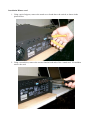
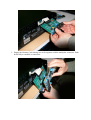
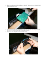
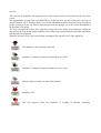
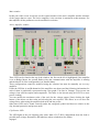
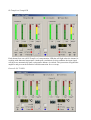
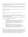
WINARC
User manual
AMPLIFIERS ...........................................................5
SESSION INFO .............................................................5
ID SPECIFICATION......................................................5
DESCRIPTION .............................................................5
REMOTE CONTROLLED CHANNELS .............................6
REMOTE CONTROL ON/OFF ........................................6
EDIT GROUPS .............................................................6
BEGIN AND END OF SESSION ............................7
DISABLING OF AN AMPLIFIER’S CONTROL 7
ICON BOX ...................................................................8
MAIN WINDOW ..........................................................9
ACTIVE AMPLIFIER WINDOW .....................................9
CLIP/LIMITER LED....................................................9
LINK ........................................................................11
GROUP CONTROL WINDOW ...........................12
LOSS OF COMMUNICATION AND RESTORATION ........12
SAFETY...................................................................12
Installation Winarc card
1. Using a pair of nippers, remove the metal cover found above the switch, as shown in the
picture below.
2. Using a screwdriver, remove the screws found at both ends of the “sound card” I/O and then
remove the card.
3. Engage the Remote Card making sure it fits together with the multipolar connector. Push
down fully to establish a connection.
4. Rotate the card being careful not to break the flat cable. Tighten the screws using the elastic
washers supplied in the kit.
5. Set the card ID using a binary identification code. Make sure this code is unequivocal and
not used for any other amplifier that is part of the installation.
6. Reinsert the card and tighten the screws on the outside.
The use of control software WinARC
After having correctly connected the PC to the interface and the latter to the amplifiers it is possible
to continue with the configuration procedure which is necessary for the correct use of the system.
Every session must be named and saved onto a disk enabling it to be reloaded at any time.
Amplifiers
An automated procedure (New session wizard) is available to facilitate the configuration operation.
To start this procedure click on File/New of the main menu found in the top left corner of the main
window.
Session info
Complete the relative data corresponding to the session name and author. The relative creation data
is automatically given by the system.
Once this operation is finished, click on Next.
ID specification
The system offers the possibility to automatically determine every individual hardware ID (every
control board inserted in the amplifiers has a specific ID) connected to the interface or inserted
manually one by one.
Make the correct choice and click on Next.
Auto detect
The system will search all the Hardware ID present from the lowest number (specified on the left)
to the highest number (specified on the right). It’s possible to leave the default data (1..99) and click
on Next. The software will automatically search all the connected amplifiers memorizing all the
Hardware ID present.
ATTENTION: do not confuse ID with Hardware ID. The first (ID) is the internal counter that
the software assigns to every connected amplifier, the second (Hardware ID) is the code which
is set on the remote card of every amplifier.
Manual insert
Click on New and specify the number of Hardware ID for every amplifier.
Description
It is now necessary to assign a description to every connected amplifier (refer to the ID reference
sheet) remembering that every name needs to help us easily identify every amplifier present in the
installation. For this reason it is advisable to insert the name and the model of the amplifier (1.9,
2.8, 3.4, 5.0) and if desired a brief description of its use (BASS L, MID R, …)
Remote controlled channels
For every amplifier it’s possible to specify if you intend to control both channels or only one
channel for that particular session.
Remote control On/off
It’s possible to specify if we want to control a particular amplifier (Remote ON) or if we prefer not
to control it (Remote OFF), in the current session.
The Edit list of amplifiers is shown in a window and to modify a particular setting, you need to
simply select one by clicking on it and press the appropriate button according to the operation you
wish to use: Edit, Move UP, Move Down.
Once this operation is finished click on close.
All the relative information regarding the amplifiers can be subsequently modified clicking on
Edit/Amplifiers.
Amplifier groups.
It’s often useful to logically put together some amplifiers in a group. For example we can group
together the amplifiers used for low frequencies (Bass) or used in a particular rehearsal room. This
enables us to set up the level, the mute and the solo function for all the amplifiers belonging to that
particular group at the same time and using just one command.
It’s possible that an amplifier can belong to more than one group. This is also true for every
individual channel of the amplifier.
This means, for example, that all the left channels present in the system can belong to the PALeft
group. At the same time, some of them, may be part of another group, for example Bass, Mid, Hi.
We can say that every single channel can be managed as an individual unit.
Edit groups
To define a group click on Edit/Groups, click on New, specify description and click on Edit List
(Blue Cross Icon) to specify which amplifier will be part of the group.
From the list of the available amplifiers on the left, select one and click on the arrow pointing right.
You will note that the selected amplifier will move from the left to the right window. To select all,
click on the double arrow. If you make a mistake you can delete one or more of the amplifiers
clicking on the opposite arrows (pointing left). Finish operation clicking on OK.
Once the composition of the group has been defined you can specify which channel (only Right,
only Left or both) for every amplifier should be controlled by the group in question.
To do this click on + beside the name of the group or double click on the name itself to expand the
layout. In this way all the names of the amplifiers in that group are shown and you can select one
with a left click and by clicking the right button of the mouse select one of the options: Both
Channels, Channel A only, Channel B only.
Repeat the operation for every amplifier belonging to the group.
If you want to further modify the composition of the group, click on the name selected then click on
Edit.
Begin and end of session
The configuration of the amplifiers and group structure is called a session. For different events we
will have different sessions that can be loaded prior to the event.
After loading or defining the structure to be used, we need to start the session by pressing Begin.
From this moment we can monitor and modify the functions of the amplifiers.
When you want to interrupt a session just click on Session/End.
Disabling of an amplifier’s control
In certain situations it may be preferable not to control an amplifier that is physically connected to
the system from the software. In order that the software no longer considers one of the amplifiers as
part of the system it’s not necessary to physically disconnect it from the network, but simply to
select Remote OFF (which means that it is not switched off, but rather not controlled by the
software).
You can do this using the menu Edit/Amplifiers, selecting one of the amplifiers and modifying the
choice Remote ON/Remote OFF. Alternatively select the icon from the box clicking on the
amplifier with the right button of the mouse and selecting the position Remote ON/Remote OFF.
You will notice also the icon will change according to the effected choice.
Organization of the icons and windows.
To activate the window control of an amplifier or a group (that is shown on the right of the screen)
you first need to click on the relative icon. This can be found in the icon box.
Icon box
The icon box of amplifiers and groups present in the current session can be found on the left of the
screen.
The organization is in the form of Tabbed Sheets: at the top there are the various tabs, the first of
which is named “ALL” displays all the icons of the individual amplifiers that have been recognized
by the system; next you can find the tab that represents the groups: every tab can be distinguished
by the name of its group.
The first icon that can be seen after selecting a group tab is the group icon which has a different
aspect from the icon for the single amplifier, then all the icons representing the individual amplifiers
in that group are displayed.
When the session is active the icons change according to the operative use of the amplifiers.
The amplifier is not correctly connected.
Amplifier’s Channel A muted or channel B set as “Solo”.
Amplifier’s Channel B muted or channel A set as “Solo”.
This icon appears when you mute both channels.
Amplifier OFF.
This icon appears when the amplifier is working in thermal protection.
Main window
In this part of the screen we always see the control window of the active amplifier and the windows
of the groups that are open. The active amplifier is the one that is monitored at that moment. For
that amplifier all the parameters can be modified in real time.
Active Amplifier window
Three LED can be found at the top of the window: the first on the left is highlighted if the amplifier
is set to Bridge Mono, the second flashes when the communication with the amplifier is running
and the third is lit if the configuration is in Parallel Mono.
These configurations cannot be modified using the software but must be manually set on every
amplifier.
Under the LED the A and B channels of the amplifiers are shown and the following information for
each of them is graphically represented using a bar graph: Vin (line in Voltage), Vout (power out
voltage), Iout (current output) and temperature. The latter is also shown using an LCD for a more
precise reading.
You can modify the maximum value of the scale for the voltage output (Vout) clicking the right
button of the mouse on that value and selecting the one required. This allows us to see how the
voltage flows when using the amplifier both at hi and low power.
Other three LED can be found vertically under the centigrade symbol and these are relative to the
clip, thermal protection and protect mode.
Clip/Limiter LED
The LED lights at the real clipping point (more than 0.5% T.H.D.) independent from the load or
possible main voltage fluctuation, and indicates (when switched on) the limiter
engaged.
Hi-Temp/Level Comp LED
Each channel has one red Hi-Temp/Level compensation LED that will light when the channel is
working with abnormal temperature (inadequate ventilation). In this condition the input signal
will decrease automatically until a temperature balance is reached. This protection safeguard the
amplifier and prevent the definitive load disconnection for over-temp.
Protect/L.S.C.™ LED
Each channel has one red Protect/L.S.C. (Load Security Control) LED that will light when: load is
disconnected (at startup session), the heatsink reach a over temperature, the load connected is lower
than 1 Ohm, the amplifier’s output is shorted.
Up to now the parameters spoken about cannot be modified but just visualized. There are however
some controls that can be used to regulate: the Solo and Mute buttons and the power level knob.
Mute
If pressed this completely interrupts the power output causing the same effect of a manual
disconnection of a loudspeaker.
Solo
If pressed this mutes all channels in the system apart from the one you wish to listen to.
Power level
Allows us to modify the level of the power output from 0 to the maximum level (99).
N.B.: in order to modify the level values via software the knobs on the amplifiers must be
turned to the maximum level position.
In order to vary the level you must first click on the control to activate it using the left click of the
mouse then you can modify the level in different ways:
•
To increase the level
o A single click on the right of the mouse causes an increase of one unit
o Keep pressed down the right of the mouse until the required level is reached
o A single hit on the “arrows up” cursor causes an increase of one unit
o Keep pressed down the “arrows up” cursor until the required level is reached
o A single hit on the “page up” cursor causes an increase of ten units
•
To decrease the level
o A single click on the left of the mouse causes a decrease of one unit
o Keep pressed down the left of the mouse until the required level is reached
o A single hit on the “arrows down” cursor causes a decrease of one unit
o Keep pressed down the “arrows down” cursor until the required level is reached
o A single hit on the “page down” cursor causes a decrease of ten units.
Link
In the center of the control window is the button “Link”, that allows us to virtually connect the
active control of two channels. This means we can simultaneously change the levels, the mute and
solo of both the channels using only the controls of channel A. You will notice that when the link is
active, the channel B control becomes disabled. It is therefore obvious to point out that all the
indicators relative to level, temperature, protection etc remain completely independent.
At any time we can reverse the link process of the two channels by pressing the Link button.
Group control window
You can open more group windows by simply clicking on the relative icon and display it in the
main part of the screen, but only one at a time can be active as is the case for the amplifiers.
The group window obviously only shows the active controls that can be modified for the whole
group: Mute, Solo and Level.
This means that if we press Mute all the channels of this group will be muted. If we press Solo all
the channels of that are not part of the group will be muted, leaving “open” all the channels of the
group in question.
Level control operates in relative mode: the default position is 0 and therefore does not increase or
decrease the original level of every amplifier. If you increase the group level (for example by 10
units) all the levels of the amplifiers belonging to the group will increase by 10 units, starting from
the original level of every individual channel.
If channel A of amplifier n. 52 is at level 35, after the group increase of 10 units, it will become 45.
Channel B of amplifier n. 83 is at level 5, it will become 15 and so on. It is clear that if the
increment of the group level takes the amplifier level over the limit it will automatically stop at 99.
At any moment you can modify the level of a single amplifier belonging to a group selecting the
icon of that particular amplifier and moving the control. The following operation of the group will
simply start from the new configuration selected for that amplifier.
Loss of communication and restoration
If the system loses communication with the amplifiers a warning will be immediately shown by
means of a special window indicating the ID of the lost amplifier. If this happens, the parameters of
the control window of that amplifier will no longer be shown, but just the words “Amplifier Local”.
From that moment the system will try to automatically reconnect the lost amplifier and if successful
control will be resumed. In any case to inform the system user that this problem has occurred, the
warning window will remain open until he confirms with a click.
Safety
When an amplifier controlled by the system becomes disconnected (by accident or on purpose) it
continues to work with the last configuration, leaving the level, mute and solo values unaltered.
This is a safety precaution in the case of a malfunction of the electric network that feeds the
computer, an operating system crash or the interruption of the control line that could cause
problems for the amplifiers during a live session.
If something happens the amplifiers will simply continue working with the last configuration that
has been set. After restoring the system we can once again modify the parameters.
To avoid restarting the wrong session accidentally, the system memorizes the current session on a
particular file named “last.rac” after every parameter modification. On rebooting the system, the last
session is automatically loaded and immediately activated to return to the exact situation prior to the
crash. You can disable the automatic re-activation (not the auto load that is always active) of the last
session selecting the menu View/Setup and pressing on the appropriate Check box named “Auto
begin last configuration”.